样例程序11:MM_S11_Viz_Timer
程序解读
以下为MM_S11_Viz_Timer样例程序的代码及相关解释说明。
| 与MM_S2_Viz_Basic样例相比,本样例仅新增了计时器的功能(加粗部分的代码)。因此,下文不再重复解释与MM_S2_Viz_Basic样例相同部分的代码(详情请参考MM_S2_Viz_Basic样例说明)。 |
   1:  !-------------------------------- ;
   2:  !FUNCTION: trigger Mech-Viz ;
   3:  !project and get planned path, ;
   4:  !add a timer to record cycle time ;
   5:  !Mech-Mind, 2023-12-25 ;
   6:  !-------------------------------- ;
   7:   ;
   8:  !set current uframe NO. to 0 ;
   9:  UFRAME_NUM=0 ;
  10:  !set current tool NO. to 1 ;
  11:  UTOOL_NUM=1 ;
  12:  !move to robot home position ;
  13:J P[1] 100% FINE    ;
  14:  !initialize communication ;
  15:  !parameters(initialization is ;
  16:  !required only once) ;
  17:  CALL MM_INIT_SKT('8','127.0.0.1',30000,5) ;
  18:  LBL[1:LOOP] ;
  19:  !reset timer to 0 ;
  20:  TIMER[1]=RESET ;
  21:  !start timer ;
  22:  TIMER[1]=START ;
  23:  !move to image-capturing position ;
  24:L P[2] 1000mm/sec FINE    ;
  25:  !trigger Mech-Viz project ;
  26:  CALL MM_START_VIZ(2,10,53) ;
  27:  !check whether viz project has ;
  28:  !been triggered successfully ;
  29:  IF (R[53]<>2103),JMP LBL[99] ;
  30:  !get planned path, 1st argument ;
  31:  !(1) means getting pose in JPs ;
  32:  CALL MM_GET_VIZ(1,51,52,53) ;
  33:  !check whether planned path has ;
  34:  !been got from Mech-Viz ;
  35:  !successfully ;
  36:  IF R[53]<>2100,JMP LBL[99] ;
  37:  !save waypoints of the planned ;
  38:  !path to local variables one ;
  39:  !by one ;
  40:  CALL MM_GET_JPS(1,60,70,80) ;
  41:  CALL MM_GET_JPS(2,61,71,81) ;
  42:  CALL MM_GET_JPS(3,62,72,82) ;
  43:  !follow the planned path to pick ;
  44:  !move to approach waypoint ;
  45:  !of picking ;
  46:J PR[60] 50% FINE    ;
  47:  !move to picking waypoint ;
  48:J PR[61] 10% FINE    ;
  49:  !add object grasping logic here, ;
  50:  !such as "DO[1]=ON" ;
  51:  PAUSE ;
  52:  !move to departure waypoint ;
  53:  !of picking ;
  54:J PR[62] 50% FINE    ;
  55:  !move to intermediate waypoint ;
  56:  !of placing ;
  57:J P[3] 50% CNT100    ;
  58:  !move to approach waypoint ;
  59:  !of placing ;
  60:L P[4] 1000mm/sec FINE Tool_Offset,PR[2]    ;
  61:  !move to placing waypoint ;
  62:L P[4] 300mm/sec FINE    ;
  63:  !add object releasing logic here, ;
  64:  !such as "DO[1]=OFF" ;
  65:  PAUSE ;
  66:  !move to departure waypoint ;
  67:  !of placing ;
  68:L P[4] 1000mm/sec FINE Tool_Offset,PR[2]    ;
  69:  !move back to robot home position ;
  70:J P[1] 100% FINE    ;
  71:  !stop timer ;
  72:  TIMER[1]=STOP ;
  73:  !save timer value to register ;
  74:  R[99]=TIMER[1]    ;
  75:  JMP LBL[1] ;
  76:  END ;
  77:   ;
  78:  LBL[99:vision error] ;
  79:  !add error handling logic here ;
  80:  !according to different ;
  81:  !error codes ;
  82:  !e.g.: status=2038 means no ;
  83:  !point cloud in ROI ;
  84:  !e.g.: status=3099 means ;
  85:  !failed to open socket ;
  86:  PAUSE ;
上述样例程序代码对应的流程如下图所示。
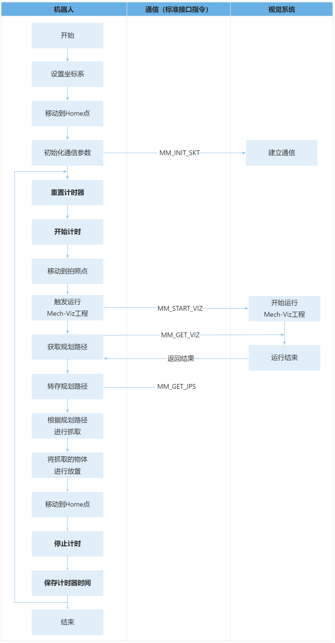
下表为计时器的逻辑解读。
| 流程 | 代码及说明 |
|---|---|
通过循环计算每次从建立通信到完成抓取与放置所花费的时间 |
上述代码表示,程序循环执行LBL[1]处的代码。 上述代码表示,将计时器TIMER[1]重置为0。 上述代码表示,计时器TIMER[1]开始计时。 上述代码表示,计时器TIMER[1]结束计时。 上述代码表示,将计时器TIMER[1]的值赋值给R[99]寄存器,方便读取计时器计算的时间(即每次从建立通信到完成抓取与放置所花费的时间)。 |