Adjust the Reference Frame of the Model

You are currently viewing the documentation for version 1.8.3. To access documentation for other versions, click the "Switch Version" button located in the upper-right corner of the page.

■ To use the latest version, visit the Mech-Mind Download Center to download it.

■ If you're unsure about the version of the product you are using, please contact Mech-Mind Technical Support for assistance.

You should set the reference frame origin at the model’s actual installation position. Doing so will align the origin of the model’s reference frame with the origin of the Model Editor’s world reference frame.

alt
Please read Selection Tool Usage Guide before proceeding to read the following content.

1. Select the model name in the “Reference Model” panel.
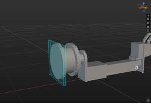
2. Click Cuboid Selection, and adjust the selection frame to enclose all the outermost vertices at the end of the flange. Since the center point is generated based on the vertices of the model, please ensure that the vertices on the part to be processed are within the selection tool.

coordinate system table1

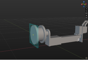
3. Click Create Center Point, and the point will be used as the origin of the reference frame.
To visualize the center point, you can right-click the center point name in the Assemblies panel and select “Show On Top” in the context menu. Or click the icon_display_transform icon to the left of the model name to hide the model.

coordinate system table2

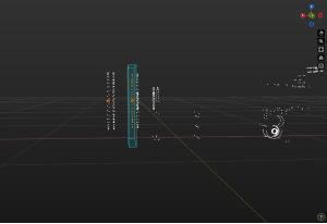
4. Click Cuboid Selection and adjust the selection frame to enclose the vertices that are parallel to the outermost vertices.
5. Click Create Center Point, and this point will be used as the reference point of the Z-axis.

coordinate system table3

6. Click Set Frame.
7. Check Select center point in the Coordinate Parameters panel on the right.
8. Click Unselected next to Coordinate Origin.
9. Click the center point in the 3D editing workspace, and a reference frame with the center point as the origin will be created.

coordinate system table4

10. Click Unselected next to Axis Z.
11. Click the reference point of Z-axis you created before in the 3D editing workspace.

coordinate system table5

12. Click OK.
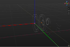
Then the model pose will change, and the origin of the world reference frame in the Model Editor will coincide with that of the model’s actual installation reference frame.

coordinate system table6

We Value Your Privacy

We use cookies to provide you with the best possible experience on our website. By continuing to use the site, you acknowledge that you agree to the use of cookies. If you decline, a single cookie will be used to ensure you're not tracked or remembered when you visit this website.