Guide for Robot Model Parameter Verification
When the robot pose or tool pose of the simulated robot in Mech-Viz is not consistent with those of the real robot, please refer to this section to verify the parameters of the robot model.
Example of Inconsistent Pose
A Kawasaki RS007N robot is used in the following example.
| In the following example, the virtual robot displayed in the simulation software provided by the robot manufacturer represents the real robot. |
-
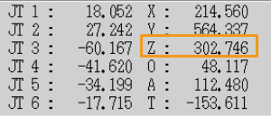
Use the teach pendant to move the real robot to a random pose, and record the values of the JPs and tool pose.
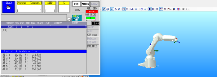
-
Search for Kawasaki RS007N in the Robot Model Library and select the robot model.
-
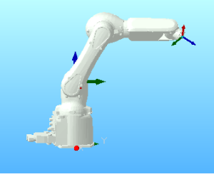
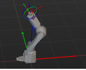
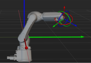
Enter the JPs values of the real robot into Mech-Viz, and the pose of the simulated robot is shown below.
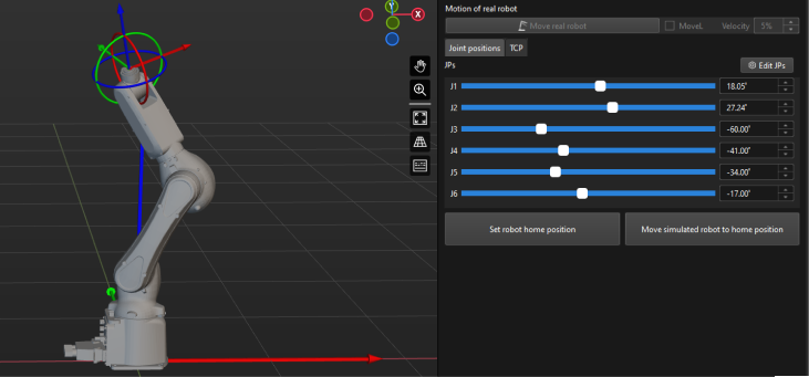
As you can tell from the two figures above, the robot poses are very different.
Verification Procedure
Please check the following items in order:
-
The orientations of the axes in the robot reference frame.
-
The rotation directions of the robot joints.
-
The poses of the robot joints.
-
The origin of the robot reference frame.
|
The items above are defined in the [robot]_algo.json file.
|
Orientations of the Axes in the Robot Reference Frame
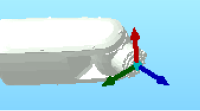
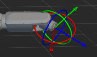
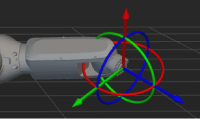
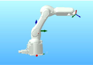
As you can see in the following figure, the real robot faces towards the positive Z-direction of its own robot reference frame, while the simulated robot faces towards the positive X-direction of its own robot reference frame.
|
|
Real robot |
Simulated robot |
| Please skip this part if the orientations of the axes in the reference frame of the real robot are consistent with their simulated counterparts. |
In this case, the X-axis and Y-axis in the robot reference frame of the simulated robot should be rotated 90° counterclockwise around the Z-axis. Please follow the steps below to resolve the difference:
-
Set the value of the robot_frame_in_robot_base_frame parameter in the kawasaki_RS007N_algo file to [0,0,0,0,0,-90] and then save the change.
-
Right-click the robot name in the project resource tree and select Reload Robot in the context menu.
-
Re-enter the JPs values of the real robot into Mech-Viz, and compare the robot poses.
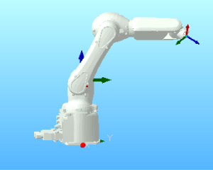
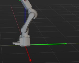
Real robot
Simulated robot
Rotation Directions of the Robot Joints
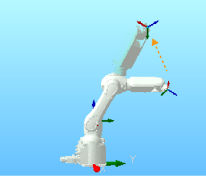
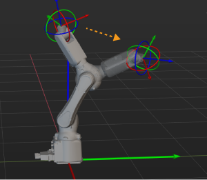
Adjust the joint positions on the teach pendant and in Mech-Viz accordingly, and compare the directions the joints rotate for the real and simulated robot.
|
|
Real robot |
Simulated robot |
| Please skip this part if the robot joint rotation directions of the real robot are consistent with their simulated counterparts. |
In this case, the J3s of the real and simulated robot rotate in opposite directions. Please follow the steps below to resolve the difference:
-
Modify the value of the axis_flip parameter in the kawasaki_RS007N_algo file from 100010 to 101010 and then save the change.
Changing 0 to 1 or 1 to 0 can flip the rotation direction of the corresponding joint. -
Right-click the robot name in the project resource tree and select Reload Robot in the context menu.
-
Rotate the joints of the robot separately and compare the axis rotation direction of the real robot with that of the simulated robot.
Poses of the Robot Joints
After correcting the joint rotation directions, re-enter the JPs or the real robot into Mech-Viz and compare the poses of the real and simulated robot.
|
|
Real robot |
Simulated robot |
| Please skip this part if the robot joint poses of the real robot are consistent with their simulated counterparts. |
According to the above robot poses, the orientations of J6 differ by 180°. Please follow the steps below to resolve the difference:
-
Modify the value of the mastering_joints parameter in the kawasaki_RS007N_algo file from [ 0, 0, 90, 0, 0, -90 ] to [ 0, 0, 90, 0, 0, 90 ] and then save the change.
-
Right-click the robot name in the project resource tree and select Reload Robot in the context menu.
Re-enter the JPs values of the real robot into Mech-Viz, and compare the robot poses.
|
|
Real robot |
Simulated robot |
Origin of the Robot Reference Frame
Before verifying the origin of the robot reference frame, please ensure that no end tool is installed on the real robot and there is no tool configuration in Mech-Viz.
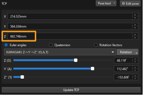
Compare the tool poses when the JPs of the real and simulated robot are the same.
|
|
Tool pose of the real robot |
Tool pose of the simulated robot |
| Please skip this part if the origin of the reference frame of the real robot is consistent with its simulated counterpart. |
As you can tell from the above figures, there is a 360 mm difference between the Z-values of the tool poses. By referring to the DH specification, the value of DH1 is 360. All this indicates that the reference frame of the real robot is not located at the bottom of the robot but at the J2.
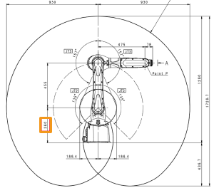
Please follow the steps below to resolve the difference:
-
Set the value of the robot_frame_in_robot_base_frame parameter in the kawasaki_RS007N_algo file to [0,0,0.36,0,0,-90] and then save the change.
-
Right-click the robot name in the project resource tree and select Reload Robot in the context menu.
-
Re-enter the JPs values of the real robot into Mech-Viz, and compare the robot poses.
|
|
Real robot |
Simulated robot |
