Tilt Correction
This tool is used to correct the tilt of the profile, which is caused by the rotation of the laser profiler around the Y-axis.
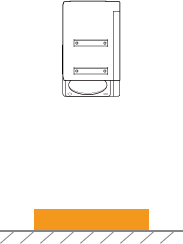
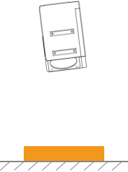
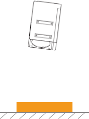
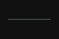
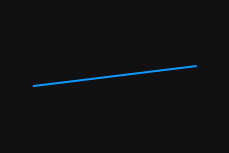
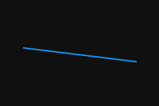
As shown below, the rotation of the laser profiler around the Y-axis makes the tilt of the acquired profile differ from the tilt of the actual object.
Not rotated |
Rotated around the Y-axis |
||
Laser profiler |
|
|
|
Acquired profile |
|
|
|
In the scan mode, click Edit to the right of Tilt Correction in the Parameters tab to open the Tilt Correction tool.
|
Prerequisites
In order to perform tilt correction, the following prerequisites must be satisfied:
-
It is recommended to use a target object whose surface includes flat regions.
-
A relatively complete profile of the flat regions can be acquired. If the profile is incomplete, please refer to Profile Mode(LNX-7000 Series) or Profile Mode(LNX-7500/LNX-8000 Series) to adjust other parameters first.
-
Keep the target object still relative to the laser profiler, and acquire the profile of the flat regions on the target object.
Instructions
Follow these steps to perform tilt correction:
-
Click Edit to the right of Tilt Correction to open the Tilt Correction window.
-
Select the detection areas and drag them to adjust their positions. Make sure to satisfy the following criterion while adjusting:
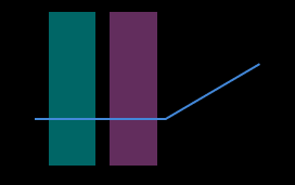
The profile selected by the two detection areas should correspond to two locations on the same flat region of the target object. Please refer to the following example:
Target object 
Detection areas
Correct
Incorrect
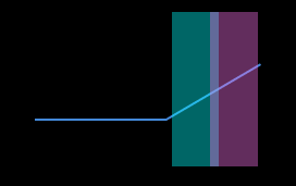
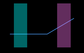
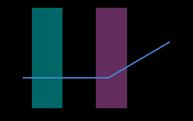
The detection areas can overlap. -
Select detection areas and drag the left or right sides to adjust their widths. Refer to the following criterion while adjusting:
With the above criterion satisfied, the detection area can be as wide as possible to include more data for tilt correction.
-
According to the model of the device, set the correction parameters:
-
LNX-7000Series: Enable Move along Z-axis if needed. Once this option is enabled, enter the target height that the corrected profile should reach in the Target Z-Axis Position.
Positive values indicate upward movement, and negative values indicate downward movement. Please re-enter each time you open the tool. -
LNX-7500/LNX-8000 Series: In Expected tilt angle under Tilt angles, enter the angle that the profile in the detection areas should reach after the correction.
Positive values rotate the profile counterclockwise; negative values rotate the profile clockwise. The range of possible values is -45.000° to 45.000°. Example of expected tilt angle
A target object as shown below is placed on a horizontal surface:
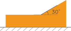
The value that should be entered for Expected tilt angle depends on the positions of the detection areas:
Detection areas Expected tilt angle 0°
30°
-
-
Click Correct. The green line in the image area on the left represents the profile after correction. Check if this profile satisfies your requirements:
-
If yes, click Apply to apply the tilt correction result and close the window.
-
If no, repeat steps 2 to 5.
-
-
Acquire data again in the profile mode and switch to Profile to check the effect of correction.