LNX-7000 Series
Technical Specifications
Model |
LNX-7030-GL |
LNX-7045-GL |
LNX-7080-GL |
||||||||
|---|---|---|---|---|---|---|---|---|---|---|---|
Data points per profile |
3200 |
||||||||||
Scan rate(1) |
Mode 1: 20–49 kHz; Mode 2: 13.5–49 kHz; Mode 3: 2–49 kHz |
||||||||||
Reference distance (RD) |
60 mm |
65 mm |
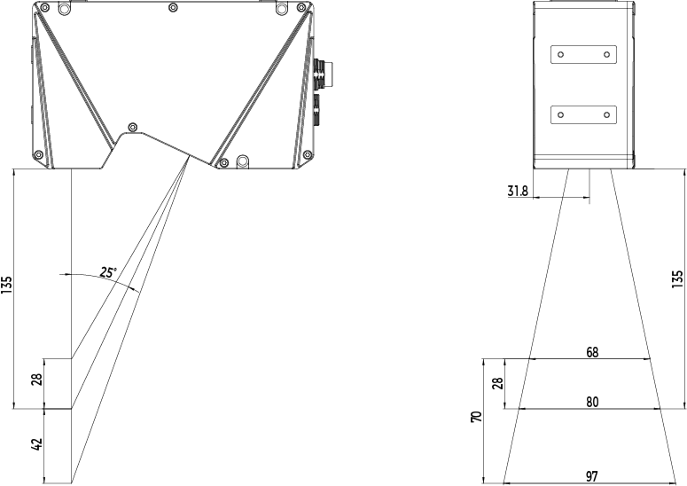
135 mm |
||||||||
Measurement range |
Z-axis |
21 mm |
31 mm |
70 mm |
|||||||
X-axis |
Near |
30 mm |
39 mm |
68 mm |
|||||||
RD |
33 mm |
45 mm |
80 mm |
||||||||
Far |
37 mm |
52 mm |
97 mm |
||||||||
X-axis resolution(2) |
11μm (9.5μm~11.5μm) |
15μm (12μm~16μm) |
25μm (21μm~30μm) |
||||||||
Z-axis resolution(3) |
1.9μm (1.5μm~2.3μm) |
2.6μm (2.0μm~3.4μm) |
5.9μm (4.0μm~8.7μm) |
||||||||
Z-axis repeatability |
0.2 μm |
0.3 μm |
0.5 μm |
||||||||
Z-axis linearity |
± 0.01% of F.S. |
± 0.015% of F.S. |
|||||||||
Weight |
0.95 kg |
0.95 kg |
1.0 kg |
||||||||
Dimensions |
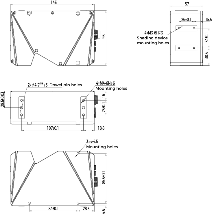
145 × 57 × 95 mm |
145 × 57 × 95 mm |
159 × 57 × 95 mm |
||||||||
Light source |
Blue laser (405 nm) |
||||||||||
Laser class |
Class 2M |
||||||||||
Lens inclination(4) |
30° |
30° |
25° |
||||||||
Operating temperature(5) |
0–45°C |
||||||||||
Operating humidity |
25%–85%, no condensation |
||||||||||
Storage temperature |
-30–70°C |
||||||||||
IP rating(6) |
IP67 |
||||||||||
Shock resistance |
15g, 6 ms pulse width, 4000 times per axis, 24000 times total, compliant with IEC 60068-2-27 |
||||||||||
Vibration resistance |
10–57 Hz, 1.5 mm peak-to-peak value, 3 hours per axis, compliant with IEC 60068-2-6 |
||||||||||
ESD protection |
Contact discharge 4 kV, air discharge 8 kV, compliant with IEC 61000-4-2 |
||||||||||
EFT protection |
±2 kV on power ports, ±1 kV on signal ports, pulse repetition frequency of 5 kHz/100 kHz, compliant with IEC 61000-4-4 |
||||||||||
Cooling |
Passive |
||||||||||
Cable |
DC power & IO cable, Ethernet cable |
||||||||||
Communication interface |
Gigabit Ethernet |
||||||||||
Input voltage |
24 VDC |
||||||||||
Peak power |
≤25 W |
||||||||||
I/O interface |
Trigger input, encoder input, digital output, and configurable I/O |
||||||||||
(1) The scan rate is related to the ROI settings. Reducing the Z-axis measurement range can increase the scan rate. Modes 1, 2, and 3 correspond to the scan rates when the ROI is set to dynamic ROI, fixed multi-window ROI, and fixed single-window ROI, respectively.
(2) The values in the table indicate the default X-axis resolution. Values in parentheses indicate the X-axis resolution range from the near side to the far side within the Z-axis measurement range.
(3) The values in the table indicate the Z-axis resolution at the reference distance. Values in parentheses indicate the Z-axis resolution range from the near side to the far side within the Z-axis measurement range.
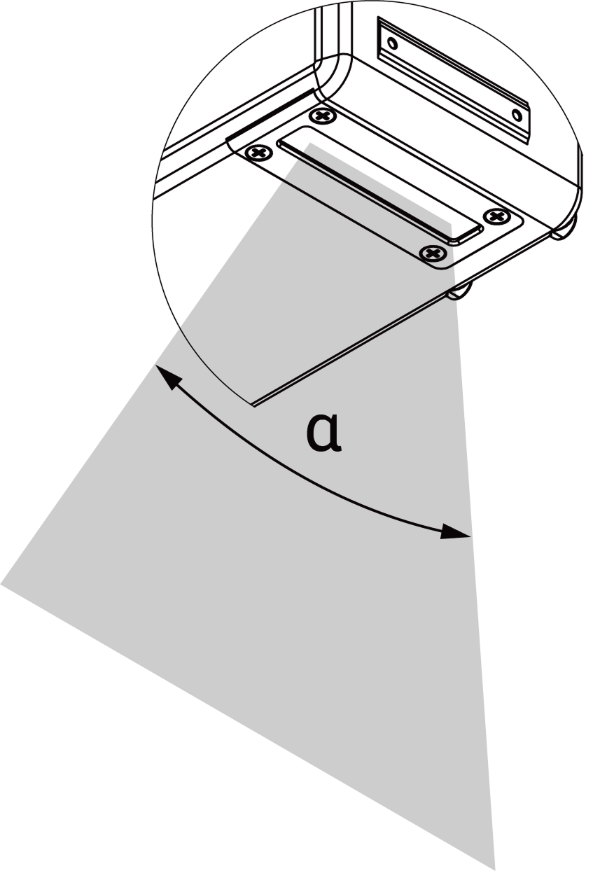
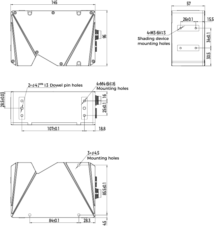
(4) Please refer to the diagrams in Field of View.
(5) When using the laser profiler in high-temperature environments, ensure proper heat dissipation and install the mounting bracket. For more details on heat-dissipation measures, please refer to the online user manual.
(6) Test implemented based on IEC 60529. 6: dust-tight; 7: waterproof.
Model |
LNX-7150-GL |
LNX-7300-GL |
LNX-7600-GL |
||||||||
|---|---|---|---|---|---|---|---|---|---|---|---|
Data points per profile |
3200 |
||||||||||
Scan rate(1) |
Mode 1: 20–49 kHz; Mode 2: 13.5–49 kHz; Mode 3: 2–49 kHz |
||||||||||
RD |
160 mm |
300 mm |
500 mm |
||||||||
Measurement range |
Z-axis |
140 mm |
310 mm |
650 mm |
|||||||
X-axis |
Near |
120 mm |
185 mm |
334 mm |
|||||||
RD |
152 mm |
254 mm |
470 mm |
||||||||
Far |
210 mm |
400 mm |
825 mm |
||||||||
X-axis resolution(2) |
50μm (38μm~66μm) |
80μm (58μm~125μm) |
150μm (105μm~258μm) |
||||||||
Z-axis resolution(3) |
10.4μm (6.3μm~20μm) |
22.5μm (11.8μm~56.9μm) |
43μm (19.2μm~136.1μm) |
||||||||
Z-axis repeatability |
1.2 μm |
2 μm |
6 μm |
||||||||
Z-axis linearity |
± 0.015% of F.S. |
± 0.02% of F.S. |
|||||||||
Weight |
1.1 kg |
1.2 kg |
1.4 kg |
||||||||
Dimensions |
177 × 55 × 95 mm |
199 × 55 × 95 mm |
300 × 57 × 95 mm |
||||||||
Light source |
Blue laser (405 nm) |
Red laser (660 nm) |
|||||||||
Laser class |
Class 2M |
Class 3R |
|||||||||
Lens inclination(4) |
27° |
21° |
23° |
||||||||
Operating temperature(5) |
0–45°C |
||||||||||
Operating humidity |
25%–85%, no condensation |
||||||||||
Storage temperature |
-30–70°C |
||||||||||
IP rating(6) |
IP67 |
||||||||||
Shock resistance |
15g, 6 ms pulse width, 4000 times per axis, 24000 times total, compliant with IEC 60068-2-27 |
||||||||||
Vibration resistance |
10–57 Hz, 1.5 mm peak-to-peak value, 3 hours per axis, compliant with IEC 60068-2-6 |
||||||||||
ESD protection |
Contact discharge 4 kV, air discharge 8 kV, compliant with IEC 61000-4-2 |
||||||||||
EFT protection |
±2 kV on power ports, ±1 kV on signal ports, pulse repetition frequency of 5 kHz/100 kHz, compliant with IEC 61000-4-4 |
||||||||||
Cooling |
Passive |
||||||||||
Cable |
DC power & IO cable, Ethernet cable |
||||||||||
Communication interface |
Gigabit Ethernet |
||||||||||
Input voltage |
24 VDC |
||||||||||
Peak power |
≤25 W |
||||||||||
I/O interface |
Trigger input, encoder input, digital output, and configurable I/O |
||||||||||
(1) The scan rate is related to the ROI settings. Reducing the Z-axis measurement range can increase the scan rate. Modes 1, 2, and 3 correspond to the scan rates when the ROI is set to dynamic ROI, fixed multi-window ROI, and fixed single-window ROI, respectively.
(2) The values in the table indicate the default X-axis resolution. Values in parentheses indicate the X-axis resolution range from the near side to the far side within the Z-axis measurement range.
(3) The values in the table indicate the Z-axis resolution at the reference distance. Values in parentheses indicate the Z-axis resolution range from the near side to the far side within the Z-axis measurement range.
(4) Please refer to the diagrams in Field of View.
(5) When using the laser profiler in high-temperature environments, ensure proper heat dissipation and install the mounting bracket. For more details on heat-dissipation measures, please refer to the online user manual.
(6) Test implemented based on IEC 60529. 6: dust-tight; 7: waterproof.
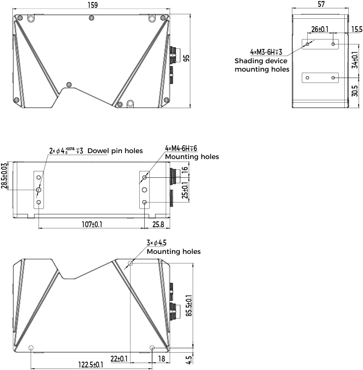
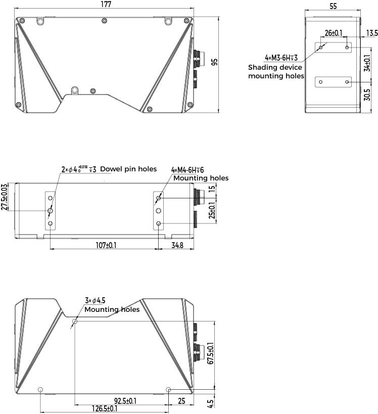
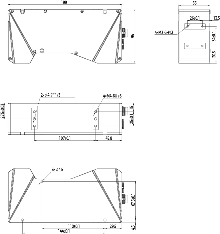
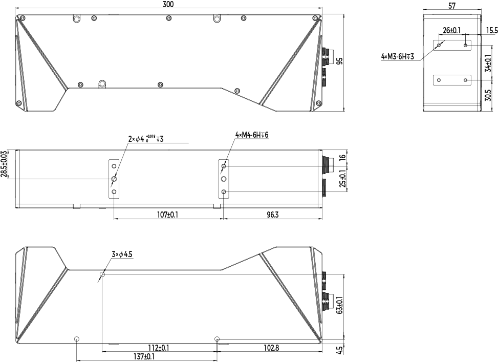
Field of View





Interface
Power I/O Interface
|
14-pin connector |

| Pin | Name | Description |
|---|---|---|
A |
+V (24 VDC) |
Power supply |
L |
-V (0 VDC) |
Power ground |
J |
Trigger_In+ |
External trigger input+ |
G |
Trigger_In- |
External trigger input- |
R |
Encoder_A+ |
Differential encoder A+ input |
S |
Encoder_A- |
Differential encoder A- input |
O |
Encoder_B+ |
Differential encoder B+ input |
P |
Encoder_B- |
Differential encoder B- input |
M |
CONFIG_IO+ |
Configurable I/O+ |
N |
CONFIG_IO- |
Configurable I/O- |
E |
Out_1+ |
Digital output 1+ |
C |
Out_1- |
Digital output 1- |
T |
Out_2+ |
Digital output 2+ |
U |
Out_2- |
Digital output 2- |
|
For the methods of triggering the laser profiler to acquire data, please refer to Methods for Triggering Data Acquisition. |
Ethernet Interface
|
14-pin connector |

| Pin | Name | Description |
|---|---|---|
M |
Ethernet MX1+ |
Ethernet differential signal line, corresponding to RJ45 connector pin 1. |
N |
Ethernet MX1- |
Ethernet differential signal line, corresponding to RJ45 connector pin 2. |
O |
Ethernet MX2+ |
Ethernet differential signal line, corresponding to RJ45 connector pin 3. |
P |
Ethernet MX2- |
Ethernet differential signal line, corresponding to RJ45 connector pin 6. |
R |
Ethernet MX3+ |
Ethernet differential signal line, corresponding to RJ45 connector pin 4. |
S |
Ethernet MX3- |
Ethernet differential signal line, corresponding to RJ45 connector pin 5. |
T |
Ethernet MX4+ |
Ethernet differential signal line, corresponding to RJ45 connector pin 7. |
U |
Ethernet MX4- |
Ethernet differential signal line, corresponding to RJ45 connector pin 8. |
|
The interface uses a 14-pin connector, with 8 pins on the inner ring for Ethernet signal transmission and the remaining pins reserved. |