Motion Direction Calibration
Overview
This tool is used to calibrate the actual motion direction of the target object relative to the laser profiler, and generate parameters (motion azimuth angle and motion elevation angle) that can be used for motion direction correction.
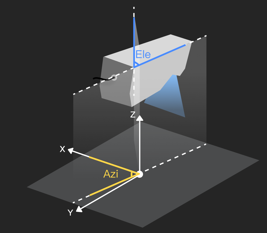
Motion azimuth angle (Azi) represents the angle between the motion direction projected onto the XY plane of the laser profiler coordinate system and the X-axis, and motion elevation angle (Ele) represents the angle between the motion direction and the Z-axis of the laser profiler coordinate system. Ideally, both are 90°, meaning the target object moves along the Y-axis direction of the laser profiler coordinate system.
Start the Feature
In the Parameters tab on the right, click the Edit button to the right of Motion Direction Correction to open the Motion Direction Calibration tool.
Motion Direction Calibration includes the following two methods:
-
Motion Direction Calibration (Auto): Automatically calculate the motion azimuth angle and motion elevation angle by scanning the calibration block for motion direction correction. Suitable for scenarios with high accuracy requirements and a controlled environment.
-
Motion Direction Calibration (Manual): Manually measure the motion azimuth angle and elevation angle, and manually input the angle values for motion direction correction. Suitable for quick on-site calibration.
Motion Direction Calibration (Auto)
| It is recommended to set the Line Scan Trigger Source to Encoder before performing automatic calibration. When using other triggering methods, calibration may fail if uniform-interval sampling along the motion direction cannot be ensured. |
Follow the steps below to complete calibration:
 Preparation
Before starting the calibration, ensure that the following preparations have been completed:
-
Confirm that the laser profiler is securely mounted and its mounting condition remains consistent during calibration and actual use.
-
Confirm that the calibration target that meets the requirements of the current scenario has been machined according to the calibration target design and machining instructions, and ensure that its placement meets the requirements.
-
Confirm that the motion path of the calibration target is consistent with the actual motion path of the target object in production.
-
Adjust the Parameters in the Mech-Eye Viewer software to ensure that the final acquired image data has no obvious missing parts and contains few minimal noise, and save the parameter group for subsequent re-acquisition and calibration.
After confirming that the preparation work is finished, click Preparations Completed , and then click Start calibration .
 Calibration Target Settings
Enter the required geometric parameters based on the type of calibration target prepared.
-
Confirm the calibration target type.
-
Target with one frustum
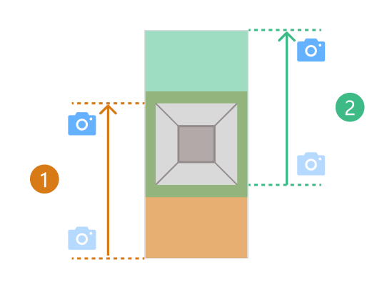
The laser profiler must scan the same frustum on the calibration target from two different starting positions. The data acquired in each scan must include the complete surface of the corresponding frustum and the surface on which the frustum is located. The two scans are shown as ① and ② in the figure below.
-
Target with two frustums
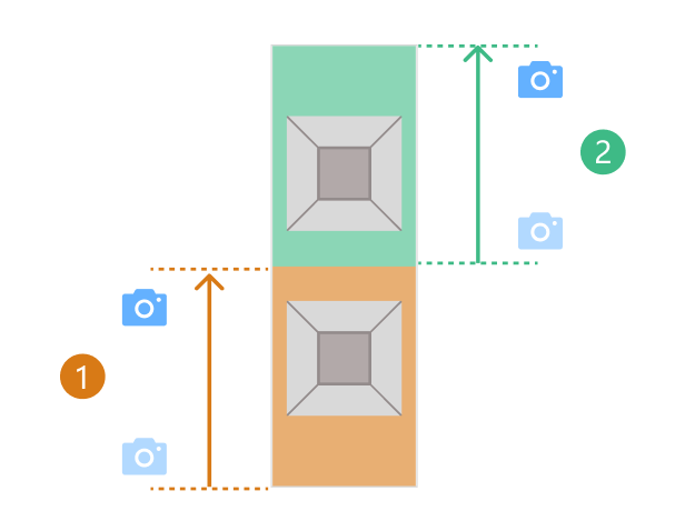
The laser profiler must scan two different frustums on the calibration target separately. The data acquired in each scan must include the complete surface of the corresponding frustum and the surface on which the frustum is located. The two scans are shown as ① and ② in the figure below.
-
-
Configure calibration target parameters.
Enter the parameter values based on the calibration target in use.
Make sure to enter accurate parameter values. 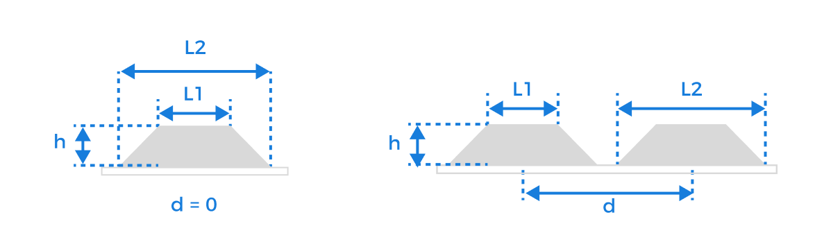
Parameter
Description
Upper base length (L1)
The side length of the frustum’s smaller base, in millimeters (mm).
Lower base length (L2)
The side length of the frustum’s larger base, in millimeters (mm).
Frustum height (h)
The vertical distance from the upper base to the lower base of the frustum, in millimeters (mm).
Translation distance (d)
The distance between the centerlines of neighboring frustums, in millimeters (mm).
When multiple frustums are arranged side by side on the calibration target, translating neighboring frustums by this distance will cause them to coincide.
After entering the accurate parameter values and confirming that they are correct, click the Next button to go to the compute calibration page.
 Compute Calibration
Follow the steps below to complete calibration:
-
Set the relative motion direction between the calibration target and the laser profiler.
Define the cable outlet direction of the laser profiler’s aviation plug as the positive direction. Please select Positive or Negative according to the actual motion relationship between the calibration target and the laser profiler:

-
Negative: The calibration target is stationary and the laser profiler moves in the direction opposite to the cable outlet direction of the aviation plug, or the laser profiler is stationary and the calibration target moves in the same direction as the cable outlet direction of the aviation plug.
-
Positive: The calibration target is stationary and the laser profiler moves in the same direction as the cable outlet direction of the aviation plug, or the profile measuring instrument is stationary and the calibration target moves in the direction opposite to the cable outlet direction of the aviation plug.
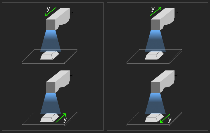
After configuration, click Next to start data acquisition.
-
-
Acquire data.
Based on the type of calibration target in use, determine the starting positions for the two acquisitions, and then click the Start Acquisition button to complete the data acquisition in sequence. After each round of data acquisition, check whether the image data meets the following requirements:
-
The calibration target should be located at the image center.
-
The image should only contain the six feature surfaces of the calibration target, with each surface fully visible and complete.
If other surface data is present, enable Use Feature Region and adjust its size and position to ensure that the region contains only the six feature surfaces of the calibration target. -
The image should have minimal noise.
Normal Severe point loss Incomplete surface Extra surface present Too much noise 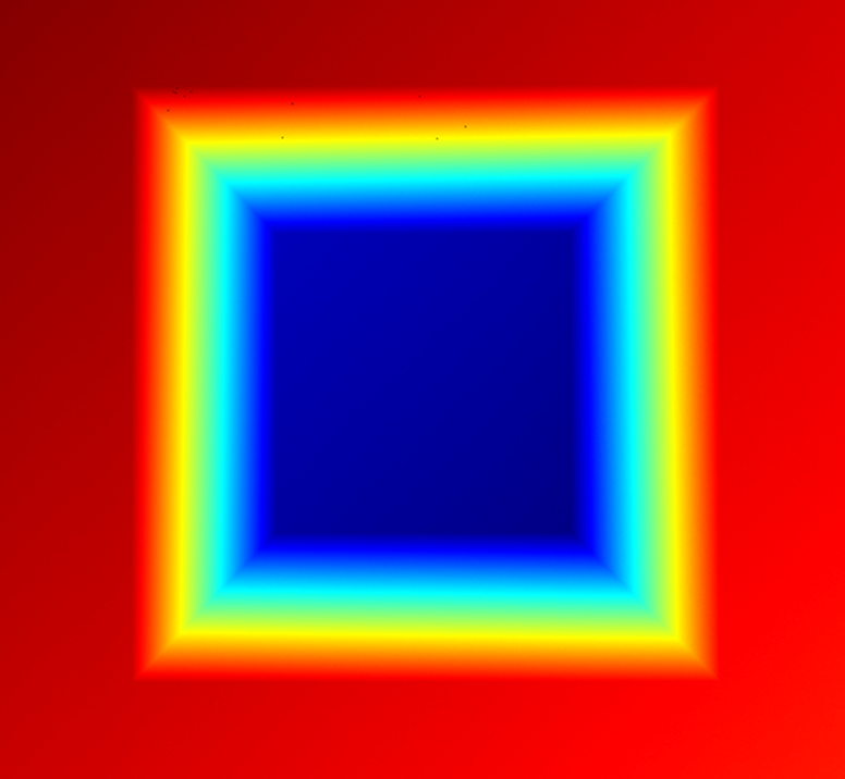
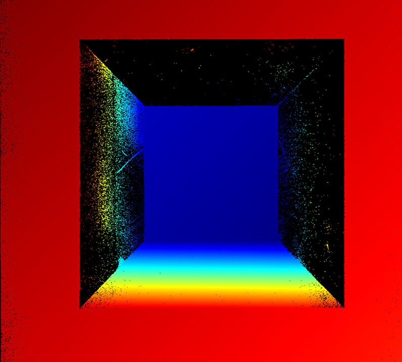
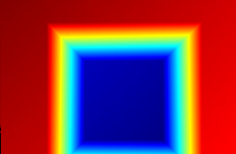
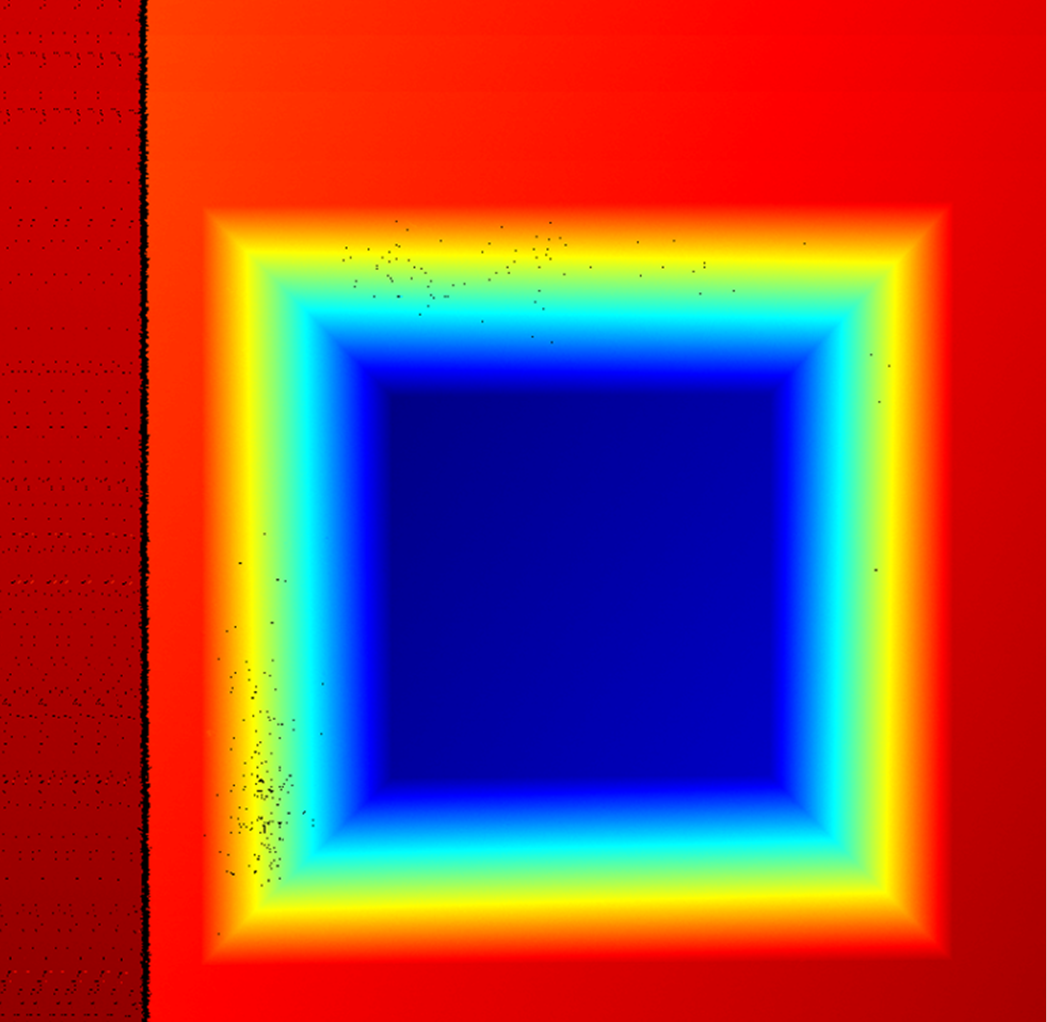
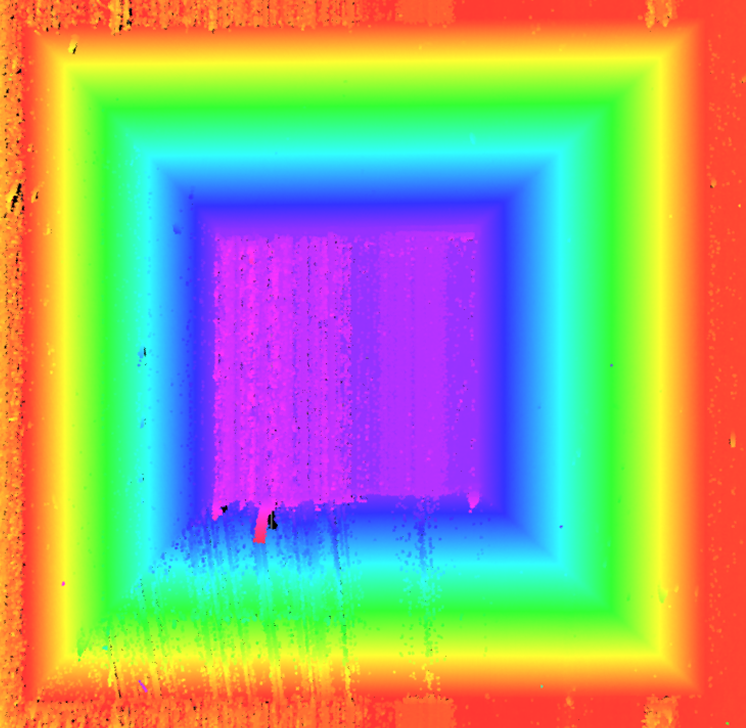
If the quality of the acquired data does not meet the requirements, exit the calibration tool and readjust the parameters until the image quality meets the requirements, and then save the parameter group. Then re-enter the calibration tool to perform calibration.
-
-
Compute calibration.
Click the Start Calibration button. The system will automatically analyze the geometric relationship of the two scan data sets, calculate the motion direction vector, and generate the calibration result.
The following information can be viewed in the result area:
-
Azimuth angle
-
Elevation angle
-
Motion direction vector
-
-
Check the calibration result to ensure that the calibration accuracy meets the requirements.
After Confirming that there are no errors, click the Save button to save the calibration result and finish the calibration.
Motion Direction Calibration (Manual)
Follow the steps below to complete calibration:
Preparation
Before starting the calibration, ensure that the following preparations have been completed:
-
Confirm that the laser profiler is securely mounted and its mounting condition remains consistent during calibration and actual use.
-
Prepare high-accuracy tools to accurately measure the azimuth angle and elevation angle of the actual motion direction of the target object.
After selecting Motion Direction Calibration (Manual), confirm item by item in the interface that the preparation work is finished, then click Preparation Completed to proceed to the next step.
Measure motion direction angle
To achieve effective calibration, please use high-accuracy tools to measure the motion azimuth angle and motion elevation angle of the actual motion direction of the target object relative to the laser profiler reference frame.
-
Set relative motion direction.
Define the cable outlet direction of the laser profiler’s aviation plug as the positive direction. According to the actual motion relationship between the target object and the laser profiler, select Positive or Negative:
-
Negative: The target object is stationary and the laser profiler moves in the direction opposite to the aviation plug outlet direction, or the laser profiler is stationary and the target object moves in the same direction as the aviation plug outlet direction.
-
Positive: The target object is stationary and the laser profiler moves in the same direction as the aviation plug outlet direction, or the laser profiler is stationary and the target object moves in the direction opposite to the aviation plug outlet direction.
After the Settings are finished, click Next to enter the angle input page.
-
-
Input motion direction angle.
-
On this page, input the motion azimuth angle (Azi) and motion elevation angle (Ele) obtained through the tool.
-
Motion azimuth angle (Azi): The value range is −180° ~ 180°, and the default value is 90°.
-
Motion elevation angle (Ele): The value range is 0° ~ 180°, with a default value of 90°.
The motion azimuth angle can be negative; please ensure the input positive or negative sign is consistent with the measurement result. It is recommended to average multiple measurements to improve accuracy.
-
-
After the input is finished, if there is a acquired image in the image display area, you can click the Preview button to view the correction effect.
-
After Confirming that there are no errors, click the Save button to save the calibration result and finish the calibration.
-
| After calibration is complete, it is recommended to keep the device installation unchanged under the same conditions. Otherwise, recalibration is required. |
Validate Calibration (Optional)
To verify the calibration, scan a reference object of known dimensions, such as a calibration target, and check whether the measurement results match the expected values. If any deviation is found, check whether the angle measurements are accurate and recalibrate if necessary.
Apply Calibration Result
After the calibration is Finish, you can enable and apply the results in the parameter area:
-
Enable the Motion Direction Correction switch.
-
Re-acquire data and confirm whether the tilt and height error of the profile have improved as expected.