Preview Mode
This topic provides descriptions of the parameters in the scan mode.
1. Brightness Settings
Parameters in this category affect the brightness of the laser lines in the raw image, thus affecting the quality of the profile, intensity image, and depth map.
-
The grayscale values of the pixels at the center of the laser lines should be between 200 and 255.
-
The recommended order of adjusting parameters is: Exposure Time > Laser Power > Analog Gain > Digital Gain
1.1. Exposure Mode
Description |
Select the exposure mode for acquiring the raw image based on the color and texture of the target object. |
|---|---|
Visibility |
Beginner, Expert |
Values |
|
Instruction |
After selecting different options, different parameters are displayed in the Brightness Settings category for adjustment:
|
1.2. Timed: Exposure Time
Description |
Set the exposure time for acquiring the raw image. Exposure time affects the brightness and width of the laser lines in the raw image, as well as the max scan rate of the laser profiler. Longer exposure time results in brighter and wider laser lines and lower max scan rate. Shorter exposure time results in darker and narrower laser lines and higher max scan rate. |
||
|---|---|---|---|
Visibility |
Beginner, Expert |
||
Values |
|
||
Instruction |
|
Raw images obtained with different Exposure Time values (all other conditions identical):
Exposure time: 5 μs |
|
|---|---|
Exposure time: 40 μs |
|
Exposure time: 400 μs |
|



1.2.1. Exposure Time Recommendation Settings
In the fixed mode, after clicking Recommended to the right of Exposure Time, the recommended exposure time will be automatically generated according to the set conditions.
Please set the laser line region and exposure time range used to calculate the recommended values before use. Please follow these steps:
-
Click Edit to the right of Exposure Time to open the Exposure Time Recommendation Settings window.
-
Sets the Laser Line ROI: Drag the dashed line in the raw image display area on the left or input the percentage values of the Left Boundary and the Right Boundary to determine the laser line ROI used to calculate the recommended exposure time.
-
Sets the Exposure Time Range: Sets the Max Exposure Time and Min Exposure Time. Maximum exposure time should ensure that the scan rate at this exposure time meets requirements, and minimum exposure time should ensure that the data quality at this exposure time meets requirements.
-
Click Apply to complete the settings.
1.3. Single Frame HDR: Exposure Time and HDR Exposure Settings
1.3.1. Exposure Time
Description |
Set the exposure time for acquiring the raw image. Exposure time affects the brightness and width of the laser lines in the raw image, as well as the max scan rate of the laser profiler. Longer exposure time results in brighter and wider laser lines and lower max scan rate. Shorter exposure time results in darker and narrower laser lines and higher max scan rate. |
||
|---|---|---|---|
Visibility |
Beginner, Expert |
||
Values |
|
||
Instruction |
|
1.3.2. HDR Exposure Settings
Description |
Set the exposure time for acquiring the raw image. Exposure time affects the brightness and width of the laser lines in the raw image, as well as the max scan rate of the laser profiler. Longer exposure time results in brighter and wider laser lines and lower max scan rate. Shorter exposure time results in darker and narrower laser lines and higher max scan rate. |
||
|---|---|---|---|
Visibility |
Beginner, Expert |
||
Values |
You can select Settings 1 to Settings 9, or you can set Exposure Time 1 and Exposure Time 2 Manually in HDR Exposure Settings. When selecting Manual:
|
||
Instruction |
For detailed instructions, refer to Adjust HDR Exposure Settings below.
|
Adjust HDR Exposure Settings
In the single-frame HDR exposure mode, each exposure is divided into two phases to ensure that, in the raw image, laser lines reflected by regions of different textures or colors can all achieve appropriate brightness.
In the single-frame HDR exposure mode, the total exposure time is determined by using the timed exposure mode.
Follow these steps to adjust the HDR exposure settings:
-
In the preview mode, find the region with the most complex textures or colors on the target object surface and acquire data.
-
Set Exposure Mode to Timed and adjust Exposure Time, until the brightness of the laser line reflected by the region least likely to overexpose on the target object meets the requirement. The value of Exposure Time when the brightness of this laser line meets the requirement is the value that should be set for Total exposure time in HDR Exposure Settings.
-
Set Exposure Mode to Single-frame HDR, and enter the exposure time determined in step 2 in Exposure Time.
-
Select a preset value in the drop-down list of HDR Exposure Settings.
-
In the preview mode, acquire data again and check the brightness of the laser lines in the raw image.
-
If the brightness of the laser lines meets the requirement, the process is completed.
-
If the brightness of the laser lines does not meet the requirements, select other preset values.
If the brightness of the laser lines still does not meet the requirements, follow these steps.
-
-
Set Exposure Mode to Timed and adjust Exposure Time, until the laser line reflected by the region most likely to overexpose on the target object is just visible in the raw image. The current value of Exposure Time is the value that should be set for Exposure time 2 in HDR Exposure Settings.
-
Set Exposure Mode to Single-frame HDR, then set HDR Exposure Settings to Manual. Click Edit to the right of HDR Exposure Settings to open the HDR Exposure Settings window.
-
Adjust Expected proportions until the value of Exposure time 2 roughly matches the exposure time determined in step 6.
-
The exposure times of the two phases should satisfy: Exposure time 1 > Exposure time 2.
If the exposure time does not satisfy the above condition after completing Step 8, click the Auto reorder button or continue adjusting the Expected proportions until the Proportion check shows OK.
-
The exposure time for each phase must be an even number. If the calculated values do not meet these requirements, the software will automatically fine-tune them.
-
-
Click Apply to close the current window. In the preview mode, acquire data again and check the brightness of the laser lines in the raw image.
-
If the brightness of the laser lines meets the requirement, the process is completed.
-
If the laser lines still have overexposed parts, please try the following solutions:
-
Increase the proportion of Exposure time 1 slightly or decrease the proportion of Exposure time 2 slightly.
-
Increase the Suppression level in HDR Overexposure Suppression.
-
-
1.4. Dual-frame HDR: Exposure Time, Exposure Time 2, and Long Exposure Weight
1.4.1. Exposure Time
Description |
Set the exposure time for acquiring the raw image. Exposure time affects the brightness and width of the laser lines in the raw image, as well as the max scan rate of the laser profiler. Longer exposure time results in brighter and wider laser lines and lower max scan rate. Shorter exposure time results in darker and narrower laser lines and higher max scan rate.
|
||
|---|---|---|---|
Visibility |
Beginner, Expert |
||
Values |
|
||
Instruction |
|
1.4.2. Exposure Time 2
Description |
Set the exposure time of the second frame (short exposure frame) in the dual-frame HDR. This frame is used to suppress the overexposure caused by the exposure of the first long frame in the bright region, and restore the visibility of the laser lines in the bright region in the raw image, thus improving the stability of profile extraction. |
|---|---|
Visibility |
Beginner, Expert |
Values |
The set value of Exposure Time 2 must be less than or equal to Exposure Time. |
Instruction |
|
1.4.3. Long Exposure Weight
Description |
Sets the weight ratio of the long exposure frame in the Dual-frame HDR fusion result. A higher value means a higher contribution of the long exposure frame in the fused result. The fused result is generated by combining the long exposure frame and the short exposure frame using the configured weights:
|
|---|---|
Visibility |
Expert |
Values |
|
Instruction |
|
1.5. Analog Gain
Description |
Increasing this parameter can enhance the brightness of the raw image. However, noise will also be amplified. |
||
|---|---|---|---|
Visibility |
Beginner, Expert |
||
Values |
|
||
Instruction |
|
Raw images acquired with different Analog Gain values (all other conditions identical):
Analog Gain: 1× |
|
|---|---|
Analog Gain: 4× |
|


1.6. Digital Gain
Description |
Increasing this parameter can enhance the brightness of the raw image. However, noise will also be amplified.
|
||
|---|---|---|---|
Visibility |
Expert |
||
Values |
|
||
Instruction |
If Analog Gain has reached its maximum value, but the laser lines are still too dark, you can increase Digital Gain. |
Raw images acquired with different Digital Gain values (all other conditions identical):
Digital Gain: 1 |
|
|---|---|
Digital Gain: 5 |
|


1.7. Laser Control
The parameters that can be adjusted in the Laser Control category differ under different Exposure Modes.
| Exposure Mode | Adjustable Parameters |
|---|---|
Timed |
Laser Power Adjustment Mode, Laser Power Value, Laser Power Adjustment Rate, Laser Operation Mode |
Single-frame HDR |
|
Dual-frame HDR |
1.7.1. Laser Power Adjustment Mode
Parameter Description |
Set the mode for adjusting the laser intensity. |
||
|---|---|---|---|
Visibility |
Beginner, Expert |
||
Values |
|
||
Instruction |
|
Laser Power Recommendation Settings
Once the Laser Power Adjustment Mode is set to Auto, you can generate the recommended values of laser power with the Laser Power Recommendation Settings tool.
Please set the Laser Line Region and Laser Power Range used to calculate the recommended values before use. Please follow these steps:
-
Click Edit to the right of Laser Power Adjustment Mode to open the Laser Power Recommendation Settings window.
-
Settings Laser Line ROI: Drag the dashed line in the raw image display area on the left or input the percentage values of the Left Boundary and the Right Boundary to determine the laser line ROI used to calculate the recommended laser power values.
-
Laser Power Range settings: Min Laser Power and Max Laser Power settings. Maximum laser power should ensure that the laser lines at this power are overexposed, and minimum laser power should ensure that the laser lines at this power are still clearly recognizable.
-
Click Apply to complete the settings.
1.7.2. Laser Power Value
Parameter Description |
Set the power of the emitted laser light, which affects the brightness of the laser lines in the raw image. |
|---|---|
Visibility |
Beginner, Expert |
Values |
|
Instruction |
If the object is light-colored, you can decrease this parameter to reduce the brightness of the laser lines. If the object is dark-colored, you can increase this parameter to enhance the brightness of the laser lines. |
1.7.3. Laser Adjustment Stability Factor
Parameter Description |
Control how fast the laser intensity changes from the current state to the target state. The smaller the value, the faster the adjustment, but it may lead to brightness fluctuations. The larger the value, the smoother the adjustment, but the slower the response. |
||
|---|---|---|---|
Visibility |
Expert |
||
Values |
|
||
Instruction |
When the brightness fluctuation is significant, you can appropriately increase this parameter; when the response speed is insufficient, you can appropriately decrease this parameter.
|
1.7.4. Laser Power 2
Parameter Description |
Once this parameter is enabled, independent laser power can be set for the second frame (short exposure frame) in a dual-frame HDR. |
|---|---|
Visibility |
Beginner |
Values |
|
Instruction |
|
Laser Power Value
Parameter Description |
Set the power of the emitted laser light, which affects the brightness of the laser lines in the raw image. This parameter is used for the second frame (short exposure frame) in the Dual-frame HDR. |
|---|---|
Visibility |
Expert |
Values |
|
Instruction |
|
1.7.5. Laser Operation Mode
Parameter Description |
Sets the laser operation mode. |
||
|---|---|---|---|
Visibility |
Beginner, Expert |
||
Values |
|
||
Instruction |
|
2. ROI
Parameter Description |
ROI defines the data processing range, reduces the amount of data to be processed, and enhances the max scan rate. You can set a fixed ROI on the X-Z plane or set a dynamic ROI that varies along the scan direction. Only fixed ROI settings are displayed in the preview mode.
|
||
|---|---|---|---|
Visibility |
Beginner, Expert |
||
Values |
Fixed (default) |
||
Instruction |
It cannot be edited in the preview mode. If you need to adjust the parameters, please set them in the Profile Mode. See ROI for details. |
3. Profile Extraction
Parameter Description |
The parameters in this category affect Profile Extraction results. |
||
|---|---|---|---|
Visibility |
Beginner, Expert |
||
Values |
|
||
Instruction |
|
3.1. Spot Selection
Description |
When the target object has complex surface reflecting conditions, the raw image might contain multiple laser lines due to situations such as interreflection. During the process of profile extraction, after the filtering of the other parameters, a pixel column may still contain multiple laser lines. This parameter specifies the laser line for profile extraction. |
||
|---|---|---|---|
Visibility |
Beginner, Expert |
||
Values |
|
||
Instruction |
Adjust this parameter based on the actual needs.
|
3.1.1. Expected Intensity Threshold
Description |
Set the expected intensity threshold for the Nearest or Farthest point selection mode. If a pixel column contains points whose intensity is not lower than this threshold, extraction points are selected from those points first according to the Nearest or Farthest distance rule. If no points in a pixel column meet this intensity threshold, valid points are still selected according to the configured distance rule. |
|---|---|
Visibility |
Beginner, Expert |
Values |
|
Instruction |
|
3.2. Intensity Adjustment
Parameter Description |
Sets the scaling factor for laser line intensity. A smaller value preserves details in bright regions; a larger value makes dark-region details more visible but may cause loss of details in bright regions. |
|---|---|
Visibility |
Expert |
Values |
|
Instruction |
|
3.3. Edge Selection
Description |
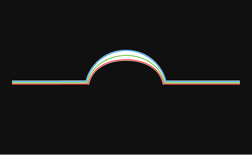
This parameter is used to select the location for extracting the profile in the laser line.
|
||
|---|---|---|---|
Visibility |
Expert |
||
Values |
|
||
Instruction |
Adjust this parameter based on the characteristics of the target object and the similarity between the profile and the actual object.
|
3.4. Detail Resolution Mode
Description |
Sets the ability to resolve fine details during laser line extraction. |
|---|---|
Visibility |
Beginner, Expert |
Values |
|
Instruction |
When the Edge Selection parameter is set to Top edge or Bottom edge, setting this parameter value to Sensitive allows the extracted profile to be closer to the edge of the laser line. |
3.5. Detection Sensitivity Mode
Parameter Description |
Set the filtering sensitivity for laser line extraction to adapt to different surface characteristics and acquisition conditions. |
|---|---|
Visibility |
Beginner, Expert |
Values |
|
Instruction |
|
3.5.1. Intensity Threshold
Description |
Sets the minimum intensity of the laser line. Pixels with intensity values lower than this threshold are treated as noise and excluded from Profile Extraction.
|
||
|---|---|---|---|
Visibility |
Beginner, Expert |
||
Values |
|
||
Instructions |
In the data display area, select Imaging Characteristic Curve. In combination with the Intensity Curve you can observe the intensity distribution of the laser lines and set Intensity Threshold. When there is too much noise and false detections are obvious, you can appropriately increase Intensity Threshold to suppress low-intensity interference points. When the profile of the weakly reflective region is prone to loss, you can appropriately decrease Intensity Threshold to retain valid points. |
Profile extraction results with different Intensity Threshold values (all other conditions identical):
Intensity Threshold: 20 |
|
|---|---|
Intensity Threshold: 50 |
|
Intensity Threshold: 70 |
|



3.5.2. Sharpness Threshold
Description |
Set the minimum sharpness of the laser lines. Pixels with grayscale values smaller than this value will not participate in Profile Extraction.
|
||
|---|---|---|---|
Visibility |
Beginner, Expert |
||
Values |
|
||
Instruction |
Increasing this parameter can exclude the laser lines produced by stray light or interreflection, which are usually too dark and blurry.
|
3.5.3. Min Effective Width
Description |
Laser line width is a property of each pixel column in a laser line. It is equal to the number of valid pixels in a pixel column.
|
|---|---|
Visibility |
Beginner, Expert |
Values |
|
Instructions |
Setting appropriate minimum and maximum widths can exclude the laser lines produced by stray light or interreflection, which are usually too wide or too narrow. After selecting Imaging Characteristic Curve in the data display area, the Effective Width Curve of the profile will be displayed below the raw image to help set Min Effective Width and Max Effective Width. For more information, refer to Effective Width Curve. |
3.5.4. Max Effective Width
Description |
Laser line width is a property of each pixel column in a laser line. It is equal to the number of valid pixels in a pixel column.
|
|---|---|
Visibility |
Beginner, Expert |
Values |
|
Instructions |
Setting appropriate minimum and maximum widths can exclude the laser lines produced by stray light or interreflection, which are usually too wide or too narrow. After selecting Imaging characteristic curves in the data display area, the Effective Width Curve of the profile will be displayed below the raw image to help set Min Effective Width and Max Effective Width. For more information, refer to Effective width curve. |
4. Interference Suppression
Parameters in this category are used to reduce interference factors and improve data quality and reliability.
4.1. Abnormal Reflection Suppression
Parameter Description |
Suppresses abnormal points caused by reflections (such as outliers and spikes), improving measurement reliability. |
|---|---|
Visibility |
Beginner, Expert |
Values |
Enable the Abnormal Reflection Suppression toggle switch:
|
Instruction |
If the target object has critical features of very small dimensions (such as vertical surfaces of narrow walls or thin plates), disabling this parameter is recommended to avoid incorrectly removing valid features. If the target object has interreflection interference, it is recommended to enable this option. |
4.2. Halo Filtering
Parameter Description |
Once this option is enabled, you can set the halo filter intensity to filter out the diffuse bright bands (halos) near the main laser line caused by strong reflections, avoiding false profile extraction. |
|---|---|
Visibility |
Beginner, Expert |
Values |
Enable the Halo Filter toggle switch:
Halo filter intensity:
|
Instruction |
|
4.3. Mask
Parameter Description |
Use masks to exclude unneeded data, such as noise and laser lines produced by interreflection. Masks are divided into Fixed Mask and Dynamic Mask.
|
||
|---|---|---|---|
Visibility |
Beginner, Expert |
||
Values |
Enable Mask toggle switch:
|
||
Instruction |
Click the Edit button to the right of Edit Mask to open the Mask Tool window and configure the settings. You can add, edit, and delete fixed masks in the tool. See the following for detailed instructions. |
4.3.1. Use Mask Tool
Through the mask tool, you can add, edit, and delete masks.
① Add Masks
Follow these steps to add masks:
-
Select the appropriate tool in the toolbar on the left:
-
 : used to add a rectangle mask.
 -
 : used to add a polygon mask.
-
-
Determine the location of the unneeded data in the raw image and draw a mask:
-
Rectangle mask: Hold and drag.
-
Polygon mask: Click to add a vertex of the polygon mask. After all needed vertices are added, press the Enter key or right-click to finish drawing the polygon mask.
In a polygon mask, the overlapped regions are not effective:

-
If the position, shape, or size of the masks are not satisfactory, you can edit the masks or delete the masks.
-
-
-
After all masks are added, click Apply to close the current window.
After you click Apply, the Enable Mask toggle switch will be turned on automatically. If the masks do need to be applied, turn off the toggle switch and acquire data again.
② Edit Masks
If the position, shape, or size of the masks are not satisfactory, follow these steps to edit the masks:
-
Click
 in the toolbar on the left.
 -
Select the mask that needs to be edited and conduct the needed adjustment:
-
Move a mask: Select the mask and drag.
-
Adjust the size of a rectangle mask: Select a vertex of the rectangle mask and drag.
-
Adjust the shape of the polygon mask: Select a vertex of the polygon mask and drag.
Click Acquire again at the top to acquire the raw image after the masks are edited to check the effect of the masks.
-
-
After all editing is completed, click Apply to close the current window.
After you click Apply, the Enable Mask toggle switch will be turned on automatically. If the masks do need to be applied, turn off the toggle switch and acquire data again.
③ Delete Masks
Follow these steps to delete unsatisfactory masks:
-
In the right panel, select the mask that needs to be deleted in Mask list, and click
 .
.If you need to delete all the masks, click Clear to the right of Mask list. -
In the pop-up window, click Confirm to delete the mask.
Click Acquire again at the top to acquire the raw image after the mask is deleted to check the effect of the remaining masks. -
After all deletion is completed, click Apply to close the current window.
After you click Apply, the Enable Mask toggle switch will be turned on automatically. If the masks do need to be applied, turn off the toggle switch and acquire data again.
5. Profile Processing
The parameters in this category process the extracted profile, improving the quality of the profile.
5.1. Outlier Removal
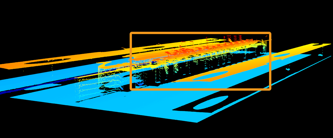
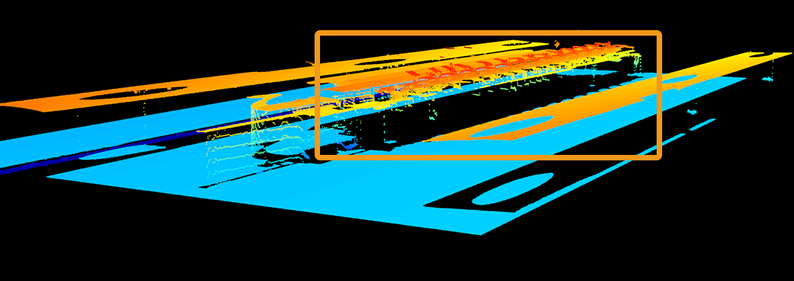
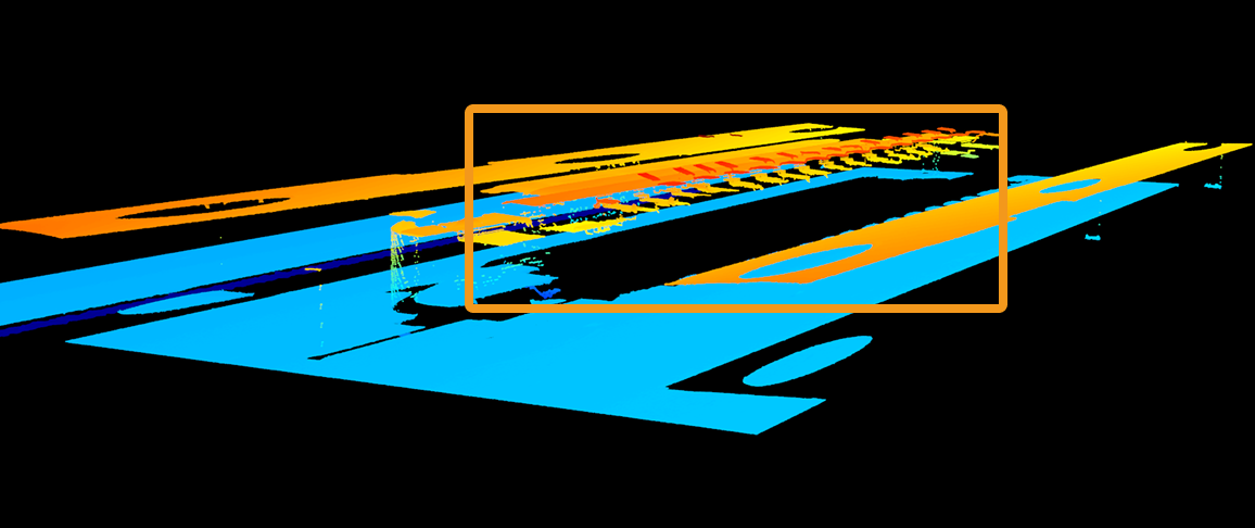
Description |
This parameter removes the outliers in each profile. Outliers are clustered points away from the object profile. |
|---|---|
Visibility |
Beginner, Expert |
Values |
|
Instruction |
A higher level of Outlier Removal Intensity removes more outliers but may also remove some surface features of the object. |
Point clouds obtained with different Outlier Removal values (all other conditions identical):
| Off | Very low | Very high |
|---|---|---|
|
|
|
5.2. Denoising Smoothing
Description |
Suppresses spike noise in the profile while largely preserving edge features. Suitable for scenarios with outliers or noticeable local interference. |
|---|---|
Visibility |
Beginner, Expert |
Values |
|
Instruction |
Sets the intensity of denoising smoothing.
|
5.2.1. Window Size
Description |
Sets the window size for denoising smoothing. |
|---|---|
Visibility |
Beginner, Expert |
Values |
|
Instruction |
Larger window size results in stronger noise suppression but may cause more profile detail loss. |
Profile extraction results with different Denoising Smoothing Window Size values (all other conditions identical):
Denoising smoothing not used |
|
|---|---|
Denoise Smoothing Window Size: 9 |
|


5.3. Uniform Smoothing
Description |
Applies uniform smoothing to the profile, reducing overall noise and data fluctuations. Suitable for scenarios with low noise and high requirements for data continuity. |
|---|---|
Visibility |
Beginner, Expert |
Values |
|
Instruction |
Sets the intensity of uniform smoothing.
|
5.3.1. Window Size
Description |
Sets the window size for uniform smoothing. |
|---|---|
Visibility |
Beginner, Expert |
Values |
|
Instruction |
Larger window size results in stronger smoothing effect but may cause more profile detail loss. |
Profile extraction results with different Uniform Smoothing Window Size values (all other conditions identical):
Uniform smoothing not used |
|
|---|---|
Uniform Smoothing Window Size: 51 |
|


5.4. Gap Filling
The parameters in this category are used to fill the gaps in the profile, improving the continuity and stability of the profile.
5.4.1. Max Gap Points
Description |
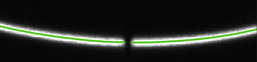
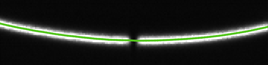
Sets the size of the gaps that can be filled in the profile. When the number of consecutive data points in a gap in the profile is no greater than this value, this gap will be filled. |
||
|---|---|---|---|
Visibility |
Beginner, Expert |
||
Values |
|
||
Instruction |
Adjust based on the size of the gaps to be filled.
|
Raw images obtained with different Gap Filling values (all other conditions identical):
Gap Filling: 0 |
|
|---|---|
Gap Filling: 5 |
|
5.4.2. Edge Preservation
Description |
This parameter sets the degree of preservation of object edges when filling gaps. |
|---|---|
Visibility |
Expert |
Values |
|
Instruction |
If you need to preserve features with abrupt depth variations, such as object edges, you can increase this parameter, but the amount of gaps being filled will decrease. |
5.4.3. Max Search Window
Description |
Sets the maximum range for searching neighboring data during gap filling. |
|---|---|
Visibility |
Expert |
Values |
|
Instruction |
The larger the value, the wider the search range, and the gaps are more likely to be filled, but edge details may be lost. |
5.4.4. Filling Method
Description |
Sets the method for gap filling. |
|---|---|
Visibility |
Expert |
Values |
|
Instruction |
|