Hardware User Manual (Integrated Laser Profiler)
Safety Instructions
|
|
Operating Environment
|
|
Mounting the Product
|
|
Using the Product
|
|
Using DIN Rail Power Supply
|
|
|
Laser Safety
|
Certifications
The product is compliant with the following standards and assessment requirements. Please note that the certification statuses may be updated. For more information, please contact the local sales agents.
Compliant with the following requirements and standards:
-
European Electromagnetic Compatibility Standards
-
U.S. ANSI C63.4, 47 CFR PART 15B, and UL 61010-1
-
Canada ICES-003
-
Japan VCCI-CISPR 32:2016
-
South Korea KS C 9832 and KS C 9835
Safety of Laser Products
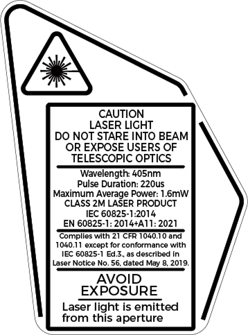
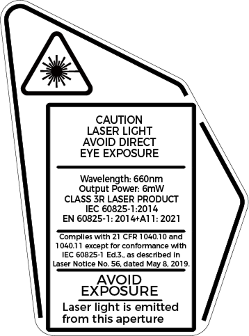
The laser classification is implemented based on IEC 60825-1:2014 and EN 60825-1:2014+A11:2021 in accordance with the requirements of Laser Notice No. 56 of the FDA (CDRH).
| Model | Max. output power | Laser class | Wavelength | Pulse duration |
|---|---|---|---|---|
LNX-7030-GL |
1.6 mW |
Class 2M |
405 nm |
220 μs |
LNX-7045-GL |
||||
LNX-7080-GL |
||||
LNX-7150-GL |
||||
LNX-7300-GL |
||||
LNX-7600-GL |
6 mW |
Class 3R |
660 nm |
- |












CE

The full text of the EU Declaration of Conformity is available at https://downloads.mech-mind.com/?tab=tab-eu-dec
European Electromagnetic Compatibility Standards:
-
EN 55032:2015+A1:2020+A11:2020
-
EN IEC 61000-3-2:2019+A1:2021
-
EN 61000-3-3:2013+A1:2019+A2:2021
-
EN 55035:2017+A11:2020

All products bearing this symbol are waste electrical and electronic equipment (WEEE as in directive 2012/19/EU) which should not be mixed with unsorted household waste. Instead, you should protect human health and the environment by handing over your waste equipment to a designated collection point for the recycling of waste electrical and electronic equipment, appointed by the government or local authorities. Correct disposal and recycling will help prevent potential negative consequences to the environment and human health. Please contact the local authorities for more information about the location as well as terms and conditions of such collection points.
FCC

NOTE: This equipment has been tested and found to comply with the limits for a Class A digital device, pursuant to part 15 of the FCC Rules. These limits are designed to provide reasonable protection against harmful interference when the equipment is operated in a commercial environment. This equipment generates, uses, and can radiate radio frequency energy and, if not installed and used in accordance with the instruction manual, may cause harmful interference to radio communications. Operation of this equipment in a residential area is likely to cause harmful interference in which case the user will be required to correct the interference at his own expense.
This device complies with part 15 of the FCC Rules. Operation is subject to the following two conditions: (1) This device may not cause harmful interference, and (2) this device must accept any interference received, including interference that may cause undesired operation of the device.
“Le présent appareil est conforme aux CNR d’Industrie Canada applicables aux appareils radio exempts de licence. L’exploitation est autorisée aux deux conditions suivantes : (1) l’appareil ne doit pas produire de brouillage, et (2) l’utilisateur de l’appareil doit accepter tout brouillage radioélectrique subi, même si le brouillage est susceptible d’en compromettre le fonctionnement.”

Package Contents
|
|
|
|
|
|
|
||
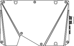
M4 × 65 bolts (Qty: 3) |
M4 × 10 bolts (Qty: 4) |
3 mm hex key (Qty: 1) |
|
|
|




|
Required Accessories
|
|
|
|


Cable Dimensions
| Model | Connector type | Lengths | Tolerance |
|---|---|---|---|
DC power & IO cable |
|||
CBLLNX-PWR-IOE-5M |
Straight |
5 m |
± 40 mm |
CBLLNX-PWR-IOE-10M |
10 m |
± 80 mm |
|
CBLLNX-PWR-IOE-20M |
20 m |
± 150 mm |
|
CBLLNX-PWR-IOE-30M |
30 m |
± 200 mm |
|
CBLLNX-PWR-IOE-5M-LU |
Right-angle |
5 m |
± 40 mm |
CBLLNX-PWR-IOE-10M-LU |
10 m |
± 80 mm |
|
CBLLNX-PWR-IOE-20M-LU |
20 m |
± 150 mm |
|
CBLLNX-PWR-IOE-30M-LU |
30 m |
± 200 mm |
|
Ethernet cable |
|||
CBLLNX-ETH-5M |
Straight |
5 m |
± 40 mm |
CBLLNX-ETH-10M |
10 m |
± 80 mm |
|
CBLLNX-ETH-20M |
20 m |
± 150 mm |
|
CBLLNX-ETH-30M |
30 m |
± 200 mm |
|
CBLLNX-ETH-5M-LU |
Right-angle |
5 m |
± 40 mm |
CBLLNX-ETH-10M-LU |
10 m |
± 80 mm |
|
CBLLNX-ETH-20M-LU |
20 m |
± 150 mm |
|
CBLLNX-ETH-30M-LU |
30 m |
± 200 mm |
|
|
For the technical specifications of cables, refer to DC power & I/O cable and Ethernet Cable. |
Optional Accessories
|
|
|
|


Cable Dimensions
| Model | Lengths | Tolerance |
|---|---|---|
CBLLNX-POWER-IOE-EXT-5M |
5 m |
± 40 mm |
CBLLNX-POWER-IOE-EXT-10M |
10 m |
± 80 mm |
|
For the technical specifications of the DIN rail power supply or DC power& IO extension cable, refer to DIN Rail Power Supply和DC Power & IO Extension Cable. |
Functional Diagrams

| No. | Name | Function |
|---|---|---|
① |
Laser emitter |
Emits laser light. |
② |
Receiver unit |
Receives the laser light reflected by the target surface. |
③ |
Ethernet Interface |
Used to connect the Ethernet cable. See Ethernet Interface for details. |
④ |
POWER indicator light |
Solid green: normal voltage |
Solid red: abnormal voltage |
||
Solid yellow: starting up |
||
⑤ |
RUN indicator light |
Blinking blue: data acquisition in progress with valid data output |
Solid blue: data acquisition in progress but no valid data output |
||
Off: no ongoing data acquisition |
||
⑥ |
LINK indicator light |
Solid green: network connected at Gigabit speed |
Solid red: network connected at Fast Ethernet speed |
||
Off: not connected to network |
||
⑦ |
Power & I/O interface |
Used to connect the DC power & IO cable. See Power I/O Interface for details. |
⑧ |
Shading device mounting hole |
Used to mount shading device onto the laser profiler. |
Mounting and Connection

|
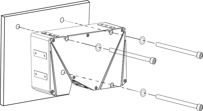
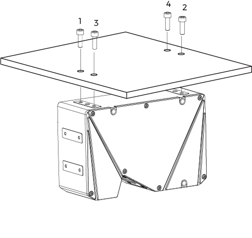
Please prepare the bracket, M4 nuts, and open-end wrench. If the bracket is too thick, please prepare M4 bolts with the appropriate length. |
Mount the Laser Profiler
Before mounting, please check the following precautions:
-
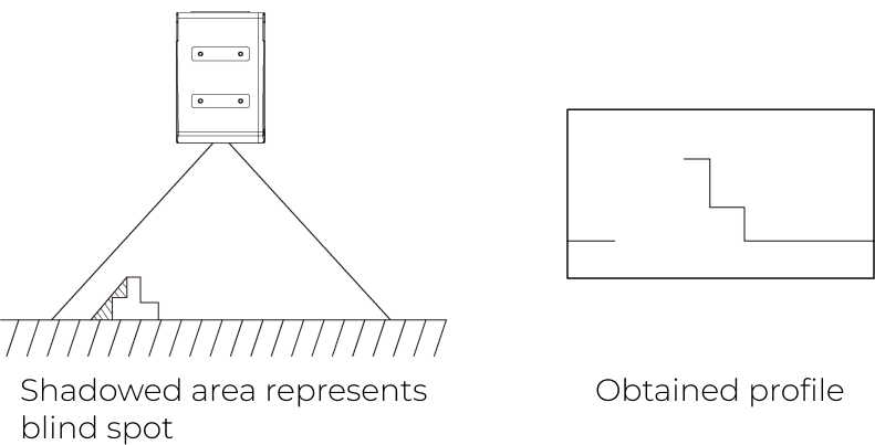
The shape of the target object may produce blind spots in the measurement range. Please evaluate the effect of blind spots on scanning before mounting the laser profiler. The laser light of this product is emitted almost in parallel, and therefore blind spots are rarely present.
-
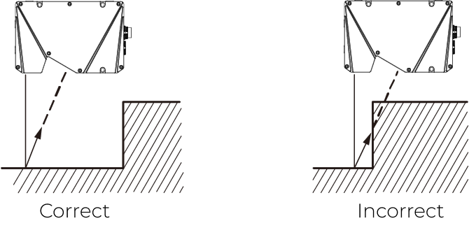
Make sure that the laser light reflected by the target object is not blocked and can reach the receiver unit.
-
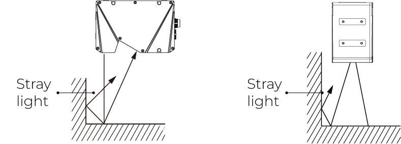
Stray light is produced if the laser light is reflected by surrounding objects such as walls. Please evaluate the effect of stray light on scanning before mounting the laser profiler.
-
To ensure that the heat from the product is well dissipated, please mount it onto a metal bracket, and make sure that the area of the bracket’s surface in contact with air is at least 3 times that of the product’s side surface.
For more details on heat-dissipation measures, refer to Heat-Dissipation Measures for Laser Profiler.
Connect Laser Profiler and IPC
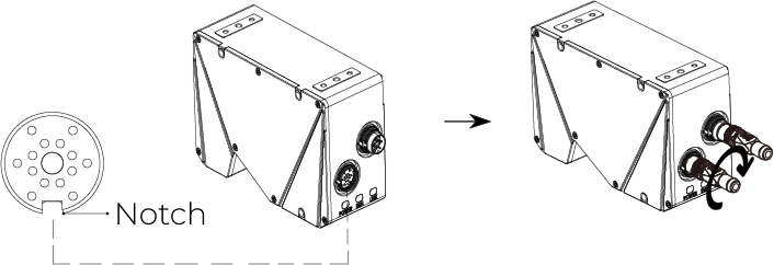
Insert the connector end of the Ethernet cable into the Ethernet interface on the laser profiler and the other end into the RJ45 Ethernet port on the IPC.

When inserting the connector of the Ethernet cable into the laser profiler, align the bump in the connector with the notch in the interface, and then tighten the nut.
|
Connect Laser Profiler and DIN Rail Power Supply
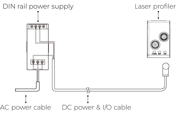
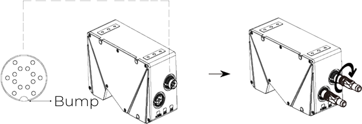
Insert the connector end of the DC power & IO cable into the Power I/O interface on the laser profiler and connect the other end to the DIN rail power supply.
When inserting the connector of the DC power & I/O cable into the laser profiler, align the notch in the connector with the bump in the interface, and then tighten the nut.
|
|
When wiring the DIN rail power supply, wires of the power cable must be inserted to the corresponding input/output terminals, as shown below.

-
Use the flat screwdriver to loosen the screws on the terminals of the DIN rail power supply.
-
Connect the DC power & IO cable: Insert the wire with the +V label into one of the +V terminals, the wire with the -V label into one of the -V terminals, and the wire with the PE label into the ground terminal (
 ).
). -
Connect the AC power cable: Insert the live wire into the L input terminal on the DIN rail power supply, the neutral wire into the N input terminal, and the ground wire into the ground terminal (
). -
Use the flat screwdriver to tighten the screws on the terminals.
|
Signal Circuit Diagrams
Input Signals
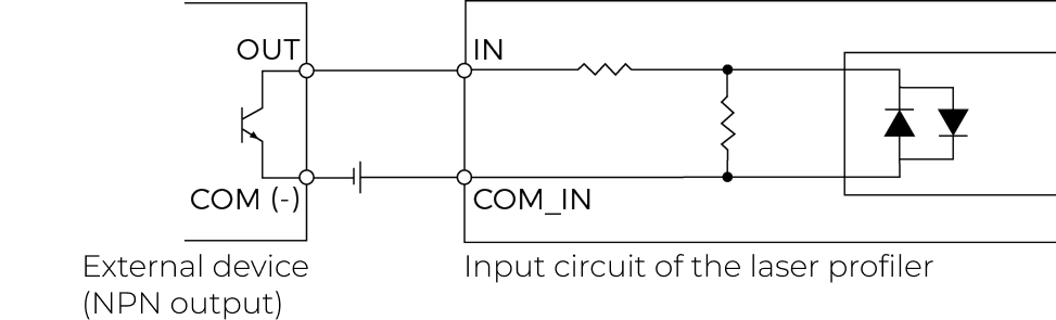
The output signals of an external device such as PLC can be inputted to the input signal terminals of the laser profiler. The following is the circuit diagram of the input signals of the laser profiler:

Logical HIGH voltage |
22–26 V |
Logical LOW voltage |
< 5 V |
Min. current |
6 mA |
Max. current |
25 mA |
Max. frequency |
100 kHz |
Isolation voltage |
2500 Vrms (min) |

Output Signals
The output signals of the laser profiler can be inputted to the input signal terminals of an external device. The following is the circuit diagram of the output signals of the laser profiler:

Logical LOW output voltage |
< 0.3 V |
Max. output current |
20 mA |
Leakage current in closed state |
< 0.5 μA |
Insulation resistance |
> 1011 Ω |
Max. frequency |
3 kHz |
Isolation voltage |
2500 Vrms (min) |

Differential encoder
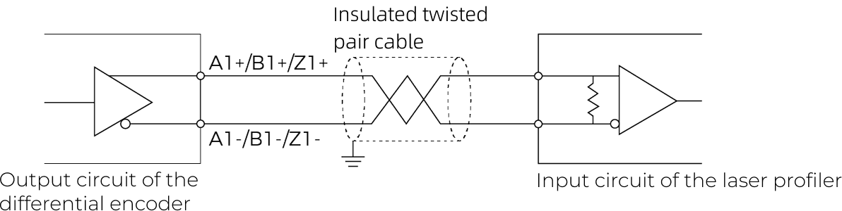
The output signals of a differential encoder can be connected to the encoder signal terminals of the laser profiler. The following is the circuit diagram of the differential encoder signals of the laser profiler:

|
When connecting the encoder, please use shielded cables suitable for RS-422 signals. |
Use the Product
Download and Install Mech-Eye SDK
The product is controlled by the accompanying software Mech-Eye SDK. Visit Mech-Mind Download Center to download and install the latest version of Mech-Eye SDK.
Use Mech-Eye SDK
Through Mech-Eye SDK, you can connect to the product and control it to acquire image and point cloud data.
|
When you connect to the product in Mech-Eye SDK for the first time, you may need to upgrade the firmware of the product. |
Maintenance
Cleaning
Disconnect the product from power before cleaning. When cleaning the surface of the product, please use a clean soft cloth to gently wipe off the dust and debris. When cleaning the windows, to avoid scratching, you can use a clean, soft lint-free cloth with lens cleaner or glass cleaner to carefully wipe the windows.
|
Storage
The product is rated as IP67. The enclosure can prevent dust and water from entering and affecting the functions of the product. Please avoid soaking the product in water or placing it outdoors for an extended period of time. When not using, please store the product in an indoor, dry, cool, and well ventilated place. The storage temperature of the product is -30–70°C.
|
Disclaimer
It is strongly recommended to use the power supply and cables provided by Mech-Mind to ensure compliance with the safety and EMC standards. Mech-Mind shall not be liable for any issues caused by using the power supply and cables provided by a third party.
Trademark and Legal Statement
Mech-Mind and Mech-Mind series logos including  are registered trademarks of Mech-Mind Robotics Technologies Co., Ltd. and other related entities.
© Copyright 2026, Mech-Mind Robotics Technologies Co., Ltd.
Unless authorized in writing in advance by Mech-Mind Robotics Technologies Co., Ltd. (“Mech-Mind”), no part of the trademarks shall be used, reproduced, modified, transmitted, transcribed, or used or sold with other products as a bundle by any entity or individual in any form for any reason.
Any infringement of Mech-Mind’s trademark rights will be punished in accordance with the law.
Mech-Mind reserves all rights regarding this user manual. According to copyright laws, unless authorized by Mech-Mind, this user manual shall not be reproduced, modified, or issued in part or in its entirety by any entity or individual. Users who purchased and use the product may download, print, or copy the user manual for personal use or use inside the belonging organization. Unless authorized by Mech-Mind, the contents of the user manual may not be used for any other purposes.