Rotation Calibration
Overview
This tool is used to calibrate the spatial relationship between the rotary table rotation axis and the laser profiler reference frame, and output calibration results that can be used for reconstruction and error compensation in rotation scenarios.
Rotational calibration is usually used in applications where the target object rotates around a fixed axis and the laser profiler is fixedly mounted.
Start the Feature
You can click Tools > Calibration > Rotation Calibration in the menu bar to open the tool.
Calibration Procedure
 Preparation
Please use calibration spheres that meet requirements and complete the following preparations.
The calibration sphere must meet the following requirements:
-
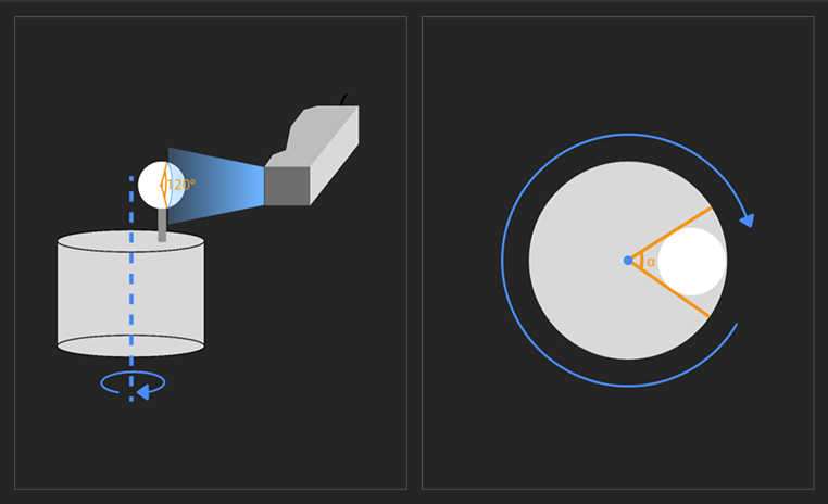
The calibration sphere must be fixed on the rotary table, and the sphere center must not coincide with the rotation axis.
-
After the calibration sphere is installed, the included angle α between the two tangents viewed from the rotation center should be no less than 30°. An angle of 90° or greater is recommended.
-
When the laser line passes through the center of the calibration sphere, the central angle corresponding to the laser coverage on the sphere surface must be greater than 120°.
| The machining accuracy of the calibration sphere will directly affect the calibration accuracy. Please ensure that the calibration spheres meet the processing requirements. |
Before starting the calibration, make sure to complete the following preparations:
-
Confirm that the calibration sphere has been manufactured according to the calibration sphere guidelines and meets the requirements of the current scenario.
-
Confirm that the calibration sphere have been placed as required.
After confirming the preparations are finished, click Preparation completed, and then click Start calibration.
 Calibration Sphere Settings
Please set the calibration sphere parameters according to the actual calibration sphere in use.
| Parameter | Description |
|---|---|
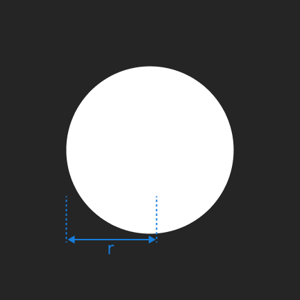
Calibration sphere radius (r) |
The actual radius of the calibration sphere (in mm). |
Angle resolution |
The rotation angle (°) of the rotary table corresponding to each row of data acquired by the laser profiler. Please fill in the data accurately according to the actual acquisition conditions. |
After configuration, click Next to open the device layout page.
 Select Layout
-
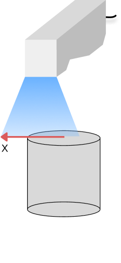
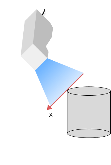
Select the relationship between the X-axis of the laser profiler and the rotary table rotation axis according to the actual mounting situation.
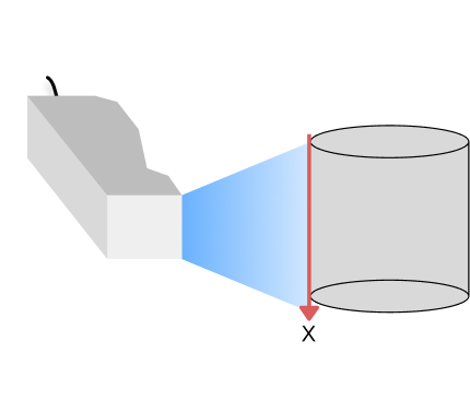
Layout Description Illustration Perpendicular
The X-axis of the laser profiler is perpendicular to the rotary table rotation axis.
Parallel
The X-axis of the laser profiler is parallel to the rotary table rotation axis.
Angled
The X-axis of the laser profiler is tilted relative to the rotation axis of the rotation table.
-
Select the rotation direction of the rotary table.
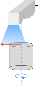
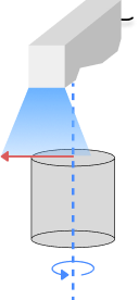
The rotation direction (Positive or Negative) is determined by the mounting position of the laser profiler. When the object rotates on the rotary table and crosses the laser line, the direction shall be Positive when the motion direction at this position matches the outgoing cable direction of the laser profiler’s aviation connector. Otherwise, it is Negative.
Direction Description Illustration Positive
The object moves in the same direction as the outgoing cable of the laser profiler’s aviation connector.
Negative
The object moves in the opposite direction from the outgoing cable of the laser profiler’s aviation connector.
After configuration, click Next to enter the calibration page.
 Compute calibration
-
Acquire data.
In the Data Acquisition area, click the Start Acquisition button to acquire data.
After data acquisition, please check if the acquired data meets the following requirements:
-
The calibration sphere is at the center of the image.
-
The image only contains the complete point cloud of the calibration sphere.
-
The image exhibits low noise.
If other surface data exists, enable Use ROI and adjust its size and position to ensure that the region contains only the calibration sphere. -
-
Compute calibration.
After data acquisition, click Start calibration. The system will transform the reference frame and calculate parameters, and generate calibration results.
In the Result area, you can view the following information:
-
A point on the rotation axis
-
Rotation axis direction vector
-
Calibration error
-
-
Check the calibration result to ensure that the calibration accuracy meets the requirements.
After confirming that the calibration result is correct, click the Save. In the pop-up window that appears, specify the file name and storage path to save the calibration result and complete the calibration.
Apply Calibration Result
After completing the rotation calibration and save the calibration result, you can load and apply the calibration result in the Mech-Eye Viewer:
-
In the Reference Frame parameters panel on the left of the data display area of the main interface, select Rotation.
-
Select the saved rotation calibration result.
-
Select Relative mode or Absolute mode according to the actual rotation scanning mode.
-
Set the angle resolution, start offset angle, and rotation direction, and then apply the result.
Rotational scanning supports the following two image restoration modes. In both modes, when the start offset angle is 0°, the first row of data is on the Y=0 plane of the rotation reference frame.
| Mode | Description |
|---|---|
Relative mode |
|
Absolute mode |
|
When applying the rotation calibration result, set the following parameters according to the actual acquisition conditions:
| Parameter | Description |
|---|---|
Angle resolution |
The rotation angle of the rotating table corresponding to each acquired row of data. The angle resolution during calibration can be different from that during the actual scanning; the angle resolution during the actual scan should be specified here. |
Start offset angle |
The angle offset of the start point in the rotation reference frame. The default value is 0° (i.e., the start point is on the Y=0 plane). If there is a known angular difference between the actual starting position and the Y=0 plane, set this parameter. |
Rotation direction |
Set the rotation direction of the rotary table during scanning to Positive or Negative. The selected direction must be consistent with the actual scanning direction. |
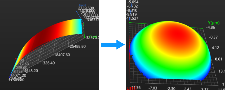
After application, the system will use the calibration result to transform the coordinates during the rotational scan, and restore the curved data to the actual shape of the object to be measured, as shown in the figure below.