LNX-7000 Series
This topic will guide you through the entire process from checking package contents to using Mech-Eye Viewer to acquire data.
|
If you have never used a laser profiler, please read the following contents first to learn the basics of laser profilers:
|
1. Check Package Contents
-
Make sure that the package is intact when you receive it.
-
Check contents according to the “packing list” in the package to ensure that no devices or accessories are missing or damaged.
|
This tutorial uses LNX-7030-GL as an example. The table below is for reference only. Please take the packing lists in the package as the final. |
|
|
|
|
|
|
|
||
M4 × 65 bolts (Qty: 3) |
M4 × 10 bolts (Qty: 4) |
3 mm hex key (Qty: 1) |
|
|
|
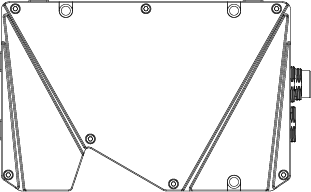




|
1.1. Required Accessories
|
|
|
|


1.1.1. Cable Dimensions
| Model | Connector type | Lengths | Tolerance |
|---|---|---|---|
DC power & IO cable |
|||
CBLLNX-PWR-IOE-5M |
Straight |
5 m |
± 40 mm |
CBLLNX-PWR-IOE-10M |
10 m |
± 80 mm |
|
CBLLNX-PWR-IOE-20M |
20 m |
± 150 mm |
|
CBLLNX-PWR-IOE-30M |
30 m |
± 200 mm |
|
CBLLNX-PWR-IOE-5M-LU |
Right-angle |
5 m |
± 40 mm |
CBLLNX-PWR-IOE-10M-LU |
10 m |
± 80 mm |
|
CBLLNX-PWR-IOE-20M-LU |
20 m |
± 150 mm |
|
CBLLNX-PWR-IOE-30M-LU |
30 m |
± 200 mm |
|
Ethernet cable |
|||
CBLLNX-ETH-5M |
Straight |
5 m |
± 40 mm |
CBLLNX-ETH-10M |
10 m |
± 80 mm |
|
CBLLNX-ETH-20M |
20 m |
± 150 mm |
|
CBLLNX-ETH-30M |
30 m |
± 200 mm |
|
CBLLNX-ETH-5M-LU |
Right-angle |
5 m |
± 40 mm |
CBLLNX-ETH-10M-LU |
10 m |
± 80 mm |
|
CBLLNX-ETH-20M-LU |
20 m |
± 150 mm |
|
CBLLNX-ETH-30M-LU |
30 m |
± 200 mm |
|
|
For the technical specifications of cables, refer to DC power & I/O cable and Ethernet Cable. |
1.2. Optional Accessories
|
|
|
|


1.2.1. Cable Dimensions
| Model | Lengths | Tolerance |
|---|---|---|
CBLLNX-POWER-IOE-EXT-5M |
5 m |
± 40 mm |
CBLLNX-POWER-IOE-EXT-10M |
10 m |
± 80 mm |
|
For the technical specifications of the DIN rail power supply or DC power& IO extension cable, refer to DIN Rail Power Supply和DC Power & IO Extension Cable. |
2. Check Ports and Indicator Lights
Refer to the following diagrams and table and check the function of each part of the laser profiler.

| No. | Name | Function |
|---|---|---|
① |
Laser emitter |
Emits laser light. |
② |
Receiver unit |
Receives the laser light reflected by the target surface. |
③ |
Ethernet Interface |
Used to connect the Ethernet cable. See Ethernet Interface for details. |
④ |
POWER indicator light |
Solid green: normal voltage |
Solid red: abnormal voltage |
||
Solid yellow: starting up |
||
⑤ |
RUN indicator light |
Blinking blue: data acquisition in progress with valid data output |
Solid blue: data acquisition in progress but no valid data output |
||
Off: no ongoing data acquisition |
||
⑥ |
LINK indicator light |
Solid green: network connected at Gigabit speed |
Solid red: network connected at Fast Ethernet speed |
||
Off: not connected to network |
||
⑦ |
Power & I/O interface |
Used to connect the DC power & IO cable. See Power I/O Interface for details. |
⑧ |
Shading device mounting hole |
Used to mount shading device onto the laser profiler. |
3. Mounting and Connection

|
Please prepare the bracket, M4 nuts, and open-end wrench. If the bracket is too thick, please prepare M4 bolts with the appropriate length. |
3.1. Mount the Laser Profiler
Before mounting, please check the following precautions:
-
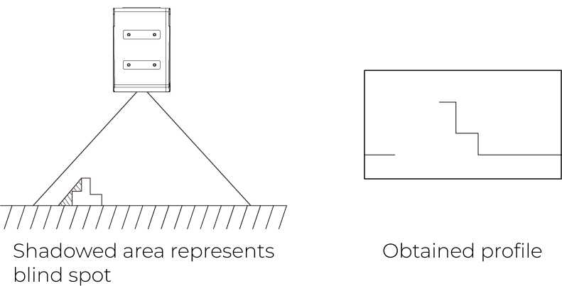
The shape of the target object may produce blind spots in the measurement range. Please evaluate the effect of blind spots on scanning before mounting the laser profiler. The laser light of this product is emitted almost in parallel, and therefore blind spots are rarely present.
-
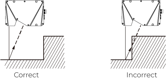
Make sure that the laser light reflected by the target object is not blocked and can reach the receiver unit.
-
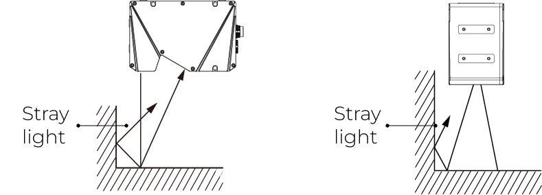
Stray light is produced if the laser light is reflected by surrounding objects such as walls. Please evaluate the effect of stray light on scanning before mounting the laser profiler.
-
To ensure that the heat from the product is well dissipated, please mount it onto a metal bracket, and make sure that the area of the bracket’s surface in contact with air is at least 3 times that of the product’s side surface.
For more details on heat-dissipation measures, refer to Heat-Dissipation Measures for Laser Profiler.
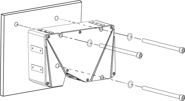
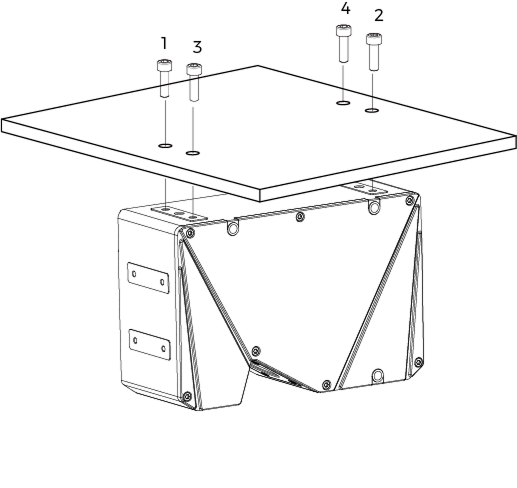
3.2. Connect Laser Profiler and IPC
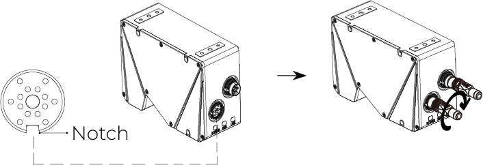
Insert the connector end of the Ethernet cable into the Ethernet interface on the laser profiler and the other end into the RJ45 Ethernet port on the IPC.

When inserting the connector of the Ethernet cable into the laser profiler, align the bump in the connector with the notch in the interface, and then tighten the nut.
|
3.3. Connect Laser Profiler and DIN Rail Power Supply
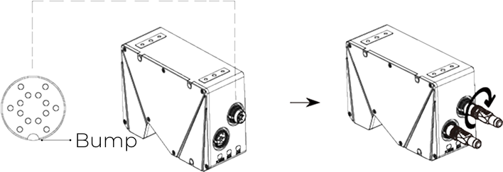
Insert the connector end of the DC power & IO cable into the Power I/O interface on the laser profiler and connect the other end to the DIN rail power supply.
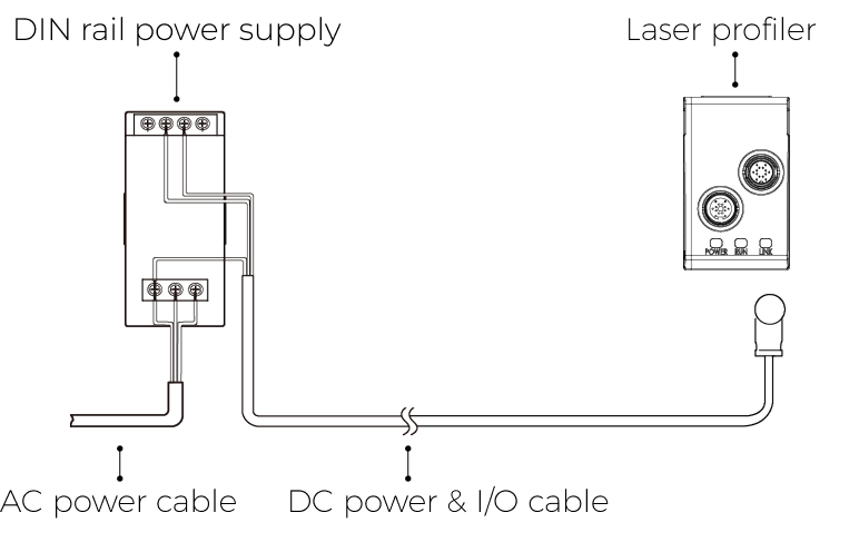
When inserting the connector of the DC power & I/O cable into the laser profiler, align the notch in the connector with the bump in the interface, and then tighten the nut.
|
|
When wiring the DIN rail power supply, wires of the power cable must be inserted to the corresponding input/output terminals, as shown below.

-
Use the flat screwdriver to loosen the screws on the terminals of the DIN rail power supply.
-
Connect the DC power & IO cable: Insert the wire with the +V label into one of the +V terminals, the wire with the -V label into one of the -V terminals, and the wire with the PE label into the ground terminal (
 ).
). -
Connect the AC power cable: Insert the live wire into the L input terminal on the DIN rail power supply, the neutral wire into the N input terminal, and the ground wire into the ground terminal (
). -
Use the flat screwdriver to tighten the screws on the terminals.
|
3.4. Connect Laser Profiler and External Devices
You can connect external devices such as PLC and encoder to the corresponding signal wires of the laser profiler’s power I/O cable, in order to control the laser profiler to acquire data or provide data acquisition status signals to the external device.
If you need to connect external devices, please refer to the following topics and determine the devices and signal wires to be connected:
The mounting and connection of the laser profiler hardware is completed. The following sections will introduce how to use Mech-Eye Viewer to connect to the laser profiler and control the laser profiler to acquire images.
4. Download and Install Mech-Eye SDK
You can download the Mech-Eye SDK installation package from Mech-Mind Download Center.
After decompressing the installation package, double-click the installer to install Mech-Eye SDK. For more information on the download, installation, upgrade, and uninstallation of Mech-Eye SDK, please refer to Mech-Eye SDK Installation Guide.
5. Set IP Addresses
Before connecting to the laser profiler, please make sure that the following IP address are unique and in the same subnet.
-
IP address of the laser profiler
-
The IP address of the computer Ethernet port connected to the laser profiler
The factory IP configuration of the laser profiler is as follows:
IP address assignment method |
Static |
|---|---|
IP address |
192.168.23.204 |
Subnet mask |
255.255.255.0 |
Gateway |
0.0.0.0 |
Follow these steps to set the laser profiler IP address:
-
Double-click to open Mech-Eye Viewer.
-
Select the laser profiler to be connected, and click
 .
.
6. Connect to Laser Profiler
-
Find the laser profiler to be connected in Mech-Eye Viewer, and click Connect.
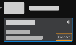
If the software or firmware needs to be upgraded, the Upgrade button is displayed instead. Please click this button to perform upgrade first, and then connect to the laser profiler.
-
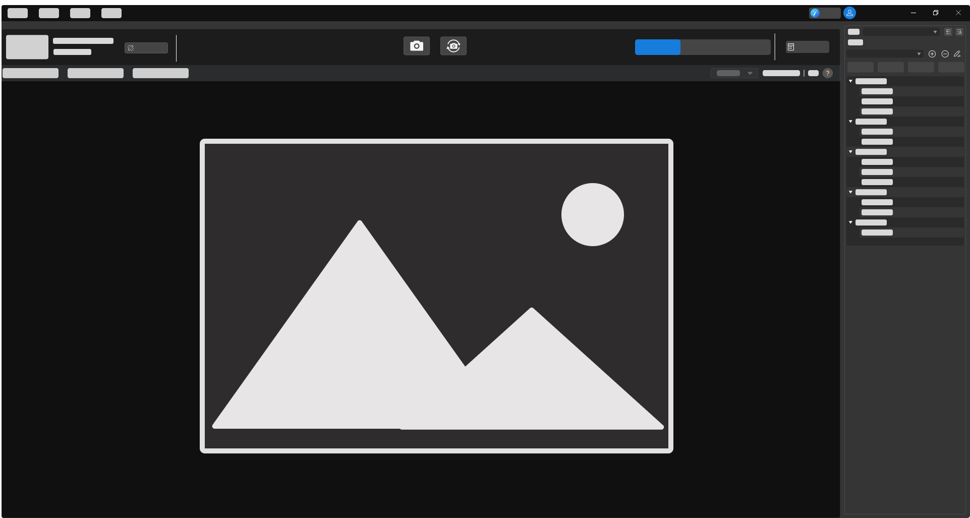
Confirm that the connection is successful. After the communication is established, the following interface appears.
7. Acquire Data
The laser profiler obtains data by scanning the object line by line. A raw image is acquired as each line is scanned. A single pixel is extracted from each column of pixels in the raw image, and this pixel is called a spot. Spots make up a profile. Finally, the profiles of many lines are combined to generate the intensity image, depth map, and point cloud.
Mech-Eye Viewer provides two data modes:
-
Preview Mode: Adjust the relevant parameters prior to profile extraction, and observe the laser line status via the raw image.
-
Profile Mode: Adjust the parameters relevant to the profile to obtain the satisfactory profile.
-
Scan Mode: Adjust the parameters relevant to the images and point cloud to obtain the satisfactory intensity image, depth map, and point cloud.
7.1. Obtain Raw Image
Follow these steps to obtain the satisfactory profile:
-
In Preview Mode, click
 to acquire one raw image.
 -
Determine if the brightness of the laser line in the raw image meet the requirement: The grayscale values of the pixels at the center of the laser line should be between 200 and 255.
Too dark

Good

Too bright

-
If the brightness of the laser line does not meet the requirement, please adjust the following parameters in the Parameters tab on the right.
The target object is made of a single material. Therefore, in the Brightness Settings category, select Timed for the Exposure Mode parameter. Now, adjusting the Exposure Time parameter will change the brightness of the laser line in the raw image.
-
Adjust the Exposure Time parameter based on the brightness of the laser line.
-
If the laser line is too dark, increase the value of the Exposure Time parameter.
-
If the laser line is too bright, decrease the value of the Exposure Time parameter.
-
-
Acquire the raw image again, and check the brightness of the laser line. If needed, keep adjusting the parameter until the brightness of the laser line meets the requirement.
If the target object is made of multiple materials or has multiple colors, you can use the Single-frame HDR or Dual-frame HDR exposure mode. For more information, please refer to Exposure Mode.
-
7.2. Obtain the Profile
After the raw image quality meets requirements, follow the steps below to obtain a valid profile:
-
Switch to Profile Mode, click
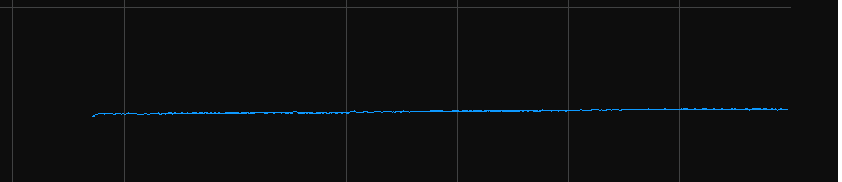
to capture one set of data. View the Profile below the acquisition button and check profile extraction results.The profile should be mostly complete without gaps.
Complete profile
Incomplete profile
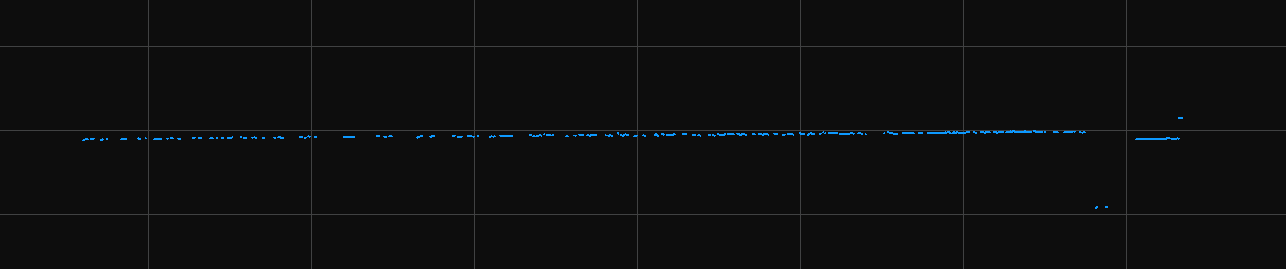
If the profile quality is not good, please adjust the brightness of the laser line in the raw image again.
7.3. Obtain Intensity Image (or Width Image), Depth Map, and Point Cloud
The profile obtained in the profile mode is the foundation for generating the intensity image (or width image), depth map, and point cloud.
After the profile meets the requirement, follow these steps to obtain one intensity image (or width image), one depth map, and one point cloud.
-
Click Scan Mode in the upper right of the interface to switch to the scan mode.
-
Set the parameters relevant to scan triggering based on the actual scenario:
-
To obtain only one intensity image (or width image) and one depth map, set Data Acquisition Method parameter to Frame-Based.
-
When the data acquisition is triggered by Mech-Eye Viewer, set the Data Acquisition Trigger Source parameter in the Trigger Settings category to Software.
-
When the scanning of each line is triggered by the encoder, set the Line Scan Trigger Source parameter in the Trigger Settings category to Encoder, Encoder A或Encoder B.
-
When the Line Scan Trigger Source is set to Encoder, for scenarios in which the target object moves unidirectionally relative to the laser profiler, configure the Trigger Direction parameter to Channel A leading (position), Channel A leading (direction), Channel B leading (position), or Channel leading (direction) based on the actual output signals from the encoder.
-
The output of the intensity image and width image is determined by the Data Type parameter under the Data Output Settings group. You can select to output the intensity image, the width image, or neither.
-
The depth map can only be output when the Sampling Method parameter under the Output Settings group is set to Uniform Spacing. Depth map output is not available when it is set to Non-uniform Spacing**.
-
-
-
Click
. The laser profiler will complete the current round of data acquisition based on the set value of the Scan Line Count parameter, and generate the intensity image, depth map (or width image), and point cloud. -
Click the data types below the acquisition buttons to view the intensity image, depth map (or width image), and point cloud.
For more information on image acquisition and data types, please refer to Acquire and View Data. -
Determine the data quality.
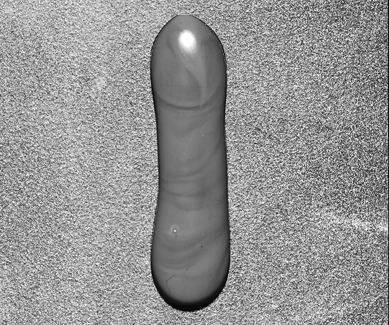
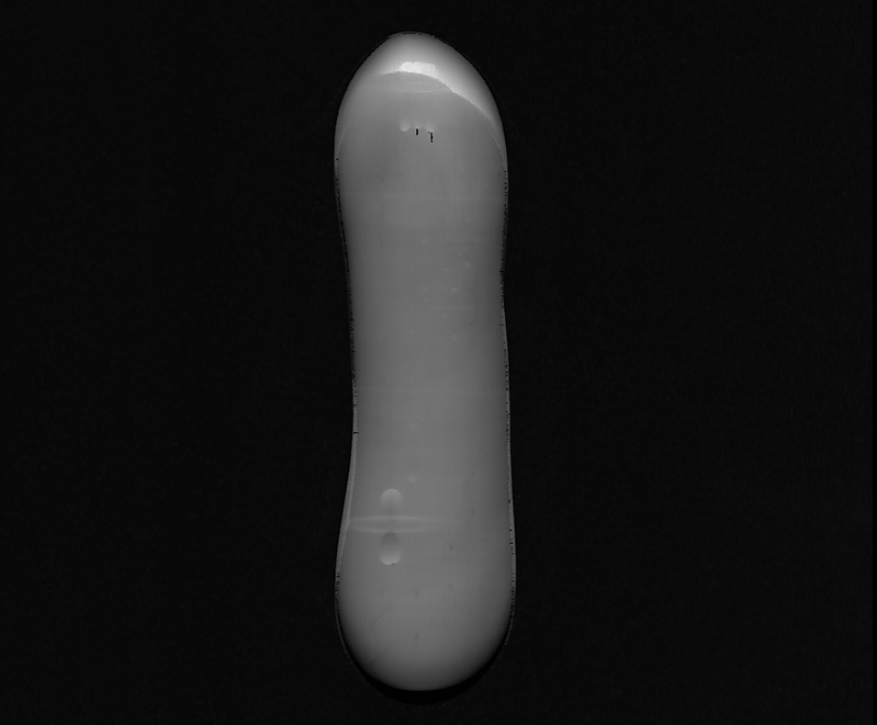
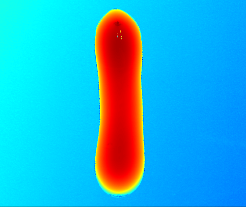
In the intensity image, width image, depth map and point cloud, the data corresponding to the target object should be complete. Refer to the following table for examples of good-quality data.
Intensity image
Width image
Depth map
Point cloud
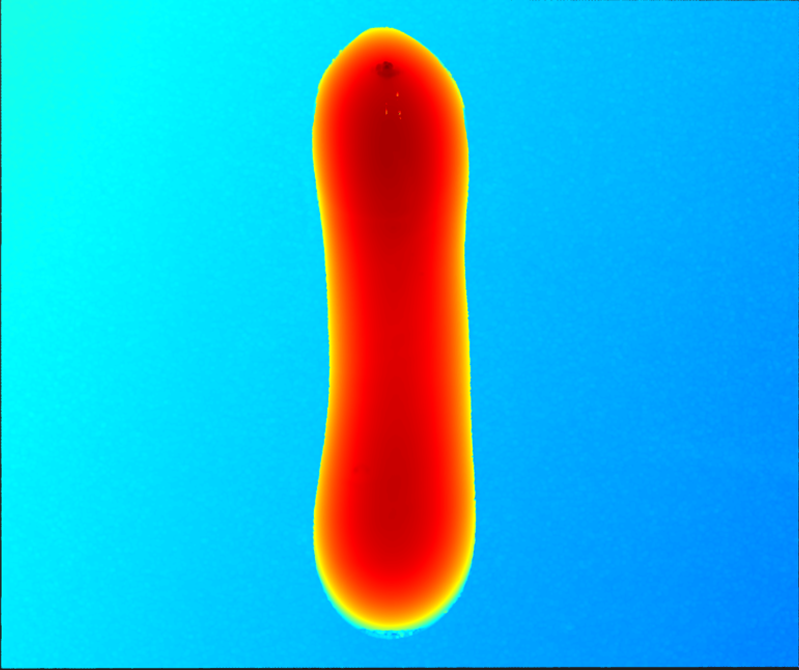
7.4. Adjust Parameters
If the obtained data is not complete, please refer to the following example and adjust the Trigger Settings parameter in the Scan Settings category:
-
Set the Scan Line Count parameter to 2000 and acquire data again. Check the intensity image. The target object in the intensity image is not complete.
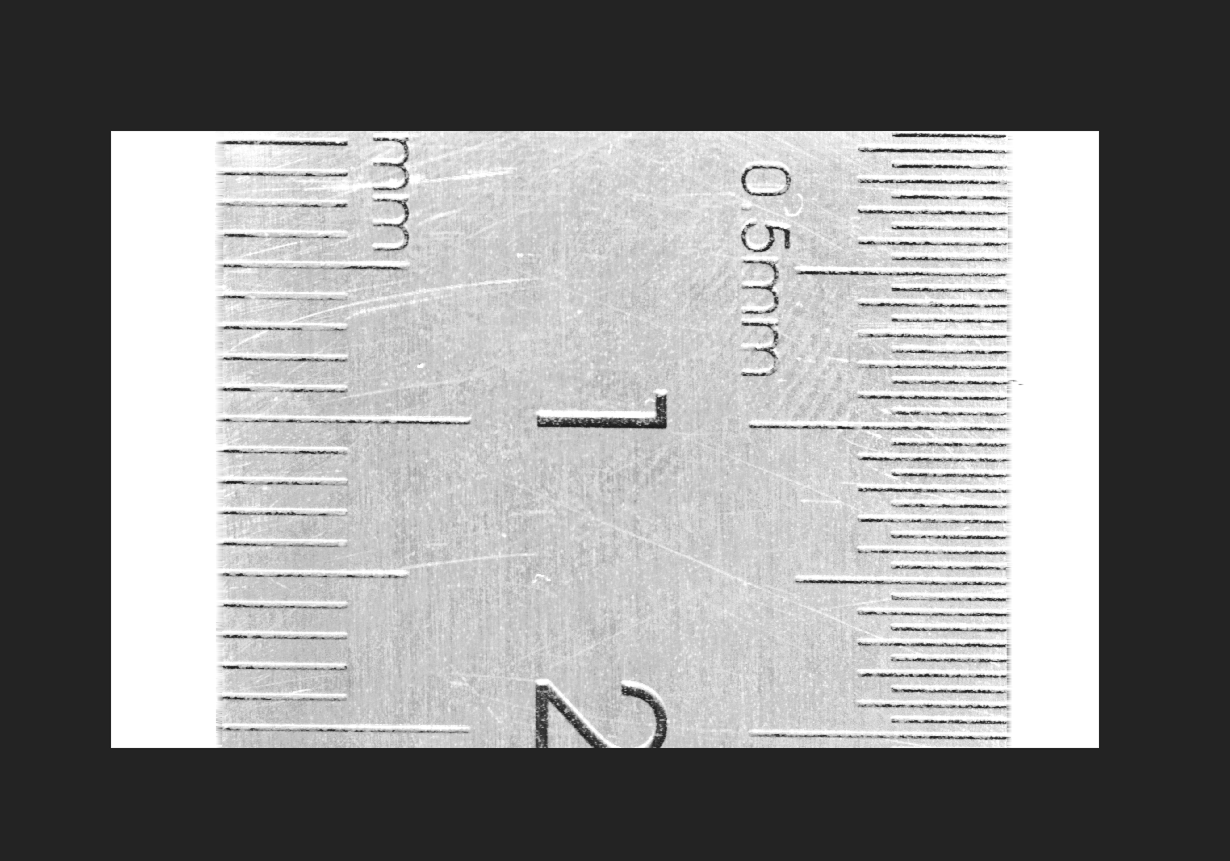
-
Increase Scan Line Count parameter (e.g. to 4000) and acquire data again. Check the intensity image; the data of the target object will be more complete.
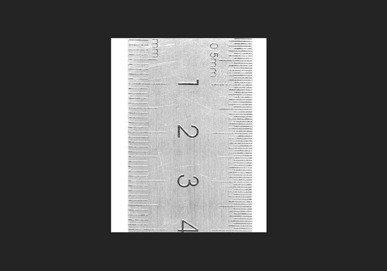
If the target object is still incomplete, further increase the Scan Lines Count until the target object in the intensity image is complete.
|
This scenario does not take into account the aspect ratio of the target object in the scan data. If you need the aspect ratio of the target object in the scan data to match that of the actual object, please adjust Trigger Signal Counting Mode and Trigger Interval. |
8. Use Data
The intensity image, depth map, and point cloud obtained through Mech-Eye Viewer can be saved locally or can be output to Mech-MSR or third-party machine vision software for subsequent processing and calculation.
-
Save the data: Click
 in the data acquisition area, set the storage path, check the data types to be saved, and then click Save.
 -
Use the data in Mech-MSR: Please refer to 3D Measurement and Inspection Tutorial and learn how to build the entire 3D measurement and inspection system that includes Mech-MSR.
-
Use the data in third-party machine vision software: The data obtained by the laser profiler can be transmitted to third-party software through Mech-Eye API or the GenICam interface.