Scan Mode
This topic introduces how to adjust the parameters in the scan mode, in order to obtain the satisfactory intensity image, depth map, and point cloud.
| Before reading this topic, please read Adjust Parameters first. |
Determine Data Quality
Determine the scan data quality according to the following criteria. If the data quality is not good, adjust the parameters according to the next section.
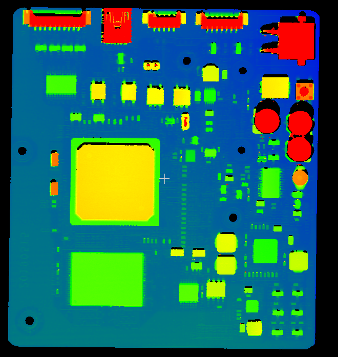
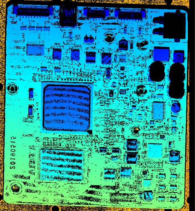
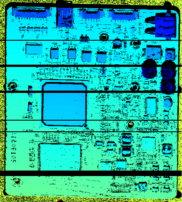
The data in the Intensity image, width map, depth map, and point cloud should be complete. The following table uses point clouds as examples.
| Data is complete | Data is incomplete | |
|---|---|---|
|
|
|
Adjust Parameters in Scan Mode
Please follow the procedure below to adjust the parameters in the scan mode. After adjusting parameters, acquire data again to check if the data quality changes.
| For the methods of triggering the laser profiler to acquire data in the scan mode, please refer to Methods for Triggering Data Acquisition. |
-
Set the Data Acquisition Method:
-
To acquire data once (scan a fixed length on the object surface) after each trigger, set this parameter to Frame-Based.
-
To continuously scan the target object after a trigger, set this parameter to Nonstop.
-
-
Adjust the rate at which scanning is triggered:
Scanning triggered by encoder
Adjust parameters in the Encoder Settings category.
Scanning triggered at fixed-rate
Adjust Trigger Rate.
-
Set the parameters in the Scan Settings category.
-
Set the height of the intensity image/depth map through Scan Line Count.
-
-
Adjust the following parameters to resolve common issues:
-
If vibration along the X-axis direction results in distortion of the edges of the target object in the intensity image, depth map, and point cloud, adjust X-Axis Profile Alignment.
-
If vibration along the Z-axis direction results in distortion of the surfaces of the target object in the intensity image, depth map, and point cloud, adjust Z-Axis Profile Alignment.
-
If the depth map and point cloud contains noise or false data, adjust the parameters in the Point Cloud Optimization category.
-
-
(Optional) Adjust the aspect ratio of the point cloud through Point Cloud Y-Axis Resolution.
|
View Acquisition Information
The following information is displayed at the bottom of the data display area:
| Information | Description |
|---|---|
Acquired Frames |
The number of acquired frames in the current scan. One frame of data is generated once the configured number of profiles set for Scan Line Count has been fully acquired. |
Number of Frames Lost |
The number of frames lost during acquisition. Usually, the trigger signal is sent too fast or repeatedly, and the device cannot respond to a new trigger signal while the previous frame is being processed. If the value continues to increase, please check the rate at which trigger signals are sent. The I/O output event can be monitored by frame triggering overrun signals. |
Max Scan Rate |
The current max scan rate. |
Scan rate in real time |
The current actual scan rate. |
Acquired Lines |
The number of acquired profiles in the current scan. |
Abnormal Rows |
The number of abnormal lines produced by overclocking during scanning. This is usually because the line scan trigger rate exceeds the maximum processing capacity of the camera. If the value continues to increase, decrease Line Scan Trigger Rate. The I/O output event can be used to monitor the Line trigger overrun signal. |