Profile Mode
This topic provides descriptions of the parameters in the profile mode.
1. Trigger Settings
Select the trigger sources and set relevant parameters.
| For the methods of triggering the laser profiler to acquire data in the scan mode, please refer to Methods for Triggering Data Acquisition. |
1.1. Data Acquisition Trigger Source
Description |
Select the source of the signals that trigger data acquisition. One round of data acquisition scans one line of data and generates one profile. |
||
|---|---|---|---|
Visibility |
Beginner, Expert |
||
Values |
|
||
Instruction |
If you use externally input signals to trigger data acquisition, select External. Otherwise, select Software.
|

1.1.1. Trigger Polarity
| This parameter is only visible when Data Acquisition Trigger Source is set to Edge Trigger. |
Description |
Sets the active direction or level state of the trigger signal. |
|---|---|
Visibility |
Expert |
Values |
|
Instruction |
Positive polarity means rising-edge triggering, and negative polarity means falling-edge triggering. |
1.1.2. Trigger Delay
Description |
Selects whether to set the trigger delay in time or line count. |
|---|---|
Visibility |
Expert |
Values |
|
Instruction |
After selecting the delay type, you need to set the corresponding Trigger Delay Time or Trigger Delay Line Count.
|
1.1.3. Debounce Time
| This parameter is only visible when Data Acquisition Trigger Source is set to Edge Trigger. |
Parameter Description |
Sets the minimum valid duration of the input signal to filter out signal jitter and glitches. When the duration is shorter than this value, the signal is considered invalid and will not trigger acquisition. |
|---|---|
Visibility |
Expert |
Values |
|
Instruction |
Setting the debounce time too large may block valid signals. The parameter value should be set based on the pulse width of the valid external input signal. |
1.2. High-Speed Mode
Parameter Description |
Enabling this parameter can improve the data acquisition speed, but the data quality may also decrease. |
|---|---|
Visibility |
Expert |
Values |
Enable High Speed Mode:
|
Instruction |
|
2. ROI
Parameter Description |
ROI defines the data processing range, reduces the amount of data to be processed, and enhances the max scan rate. Support setting Fixed ROI on the X-Z plane or Dynamic ROI that varies along the scan direction.
|
||||||||||||||
|---|---|---|---|---|---|---|---|---|---|---|---|---|---|---|---|
Visibility |
Beginner, Expert |
||||||||||||||
Values |
|
||||||||||||||
Instruction |
Follow these steps to set a fixed ROI:
|
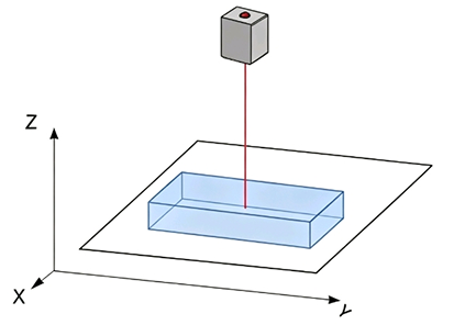
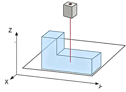
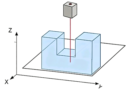
Value ranges of different models:
| Model | X-Axis Width (mm) | X-Axis Start Position (mm) | Z-Axis Height (mm) | Z-Axis End Position (mm) |
|---|---|---|---|---|
LNX-7030-GL |
0.1~37 |
-18.5~18.4 |
0.1~21 |
-11~9.9 |
LNX-7045-GL |
0.1~52 |
-26~25.9 |
0.1~31 |
-16~14.9 |
LNX-7080-GL |
0.1~97 |
-48.5~48.4 |
0.1~70 |
-42~27.9 |
LNX-7150-GL |
0.1~210 |
-105~104.9 |
0.1~140 |
-90~49.9 |
LNX-7300-GL |
0.1~400 |
-200~199.9 |
0.1~310 |
-210~99.9 |
LNX-7600-GL |
0.1~825 |
-412.5~412.4 |
0.1~650 |
-470~179.9 |
3. Profile Processing
The parameters in this category process the extracted profile, improving the quality of the profile.
3.1. Outlier Removal
Description |
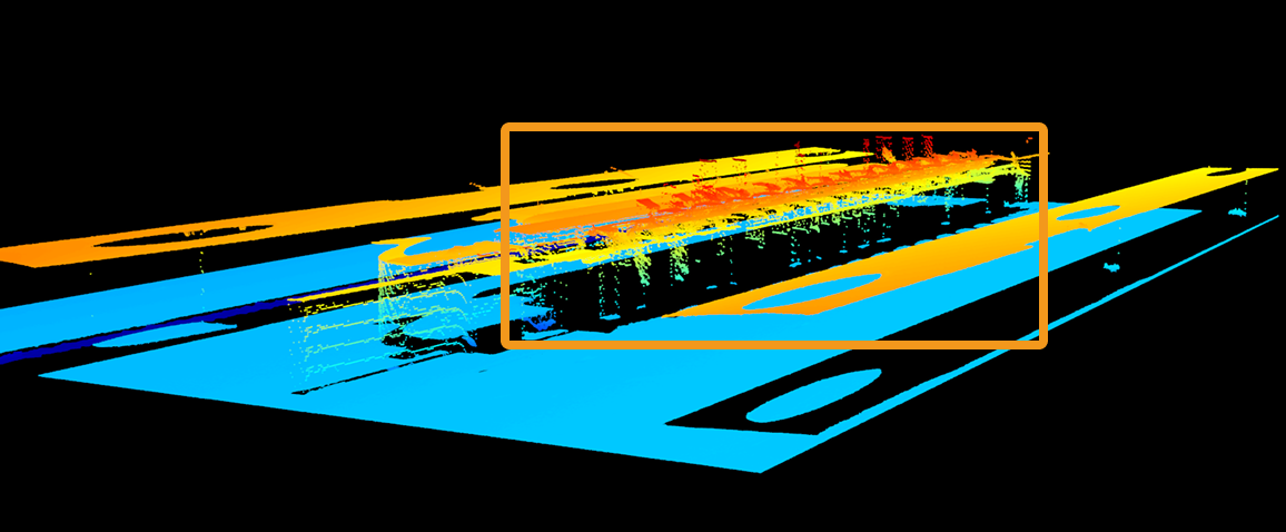
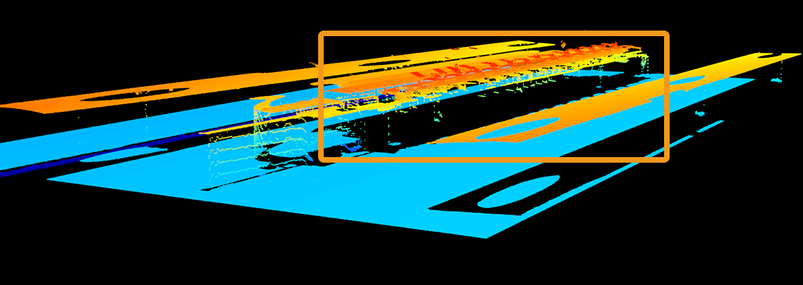
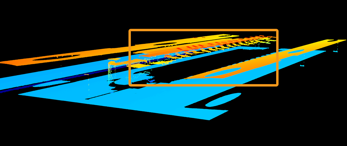
This parameter removes the outliers in each profile. Outliers are clustered points away from the object profile. |
|---|---|
Visibility |
Beginner, Expert |
Values |
|
Instruction |
A higher level of Outlier Removal Intensity removes more outliers but may also remove some surface features of the object. |
Point clouds obtained with different Outlier Removal values (all other conditions identical):
| Off | Very low | Very high |
|---|---|---|
|
|
|
3.2. Denoising Smoothing
Description |
Suppresses spike noise in the profile while largely preserving edge features. Suitable for scenarios with outliers or noticeable local interference. |
|---|---|
Visibility |
Beginner, Expert |
Values |
|
Instruction |
Sets the intensity of denoising smoothing.
|
3.2.1. Window Size
Description |
Sets the window size for denoising smoothing. |
|---|---|
Visibility |
Beginner, Expert |
Values |
|
Instruction |
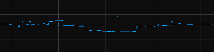
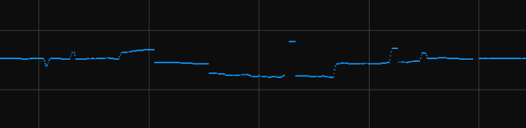
Larger window size results in stronger noise suppression but may cause more profile detail loss. |
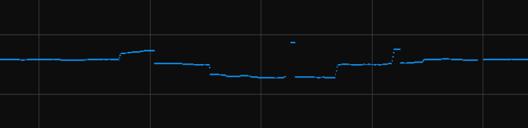
Profile extraction results with different Denoising Smoothing Window Size values (all other conditions identical):
Denoising smoothing not used |
|
|---|---|
Denoising smoothing window size: 5 |
|
Denoising smoothing window size: 9 |
|
3.3. Uniform Smoothing
Description |
Applies uniform smoothing to the profile, reducing overall noise and data fluctuations. Suitable for scenarios with low noise and high requirements for data continuity. |
|---|---|
Visibility |
Beginner, Expert |
Values |
|
Instruction |
Sets the intensity of uniform smoothing.
|
3.3.1. Window Size
Description |
Sets the window size for uniform smoothing. |
|---|---|
Visibility |
Beginner, Expert |
Values |
|
Instruction |
Larger window size results in stronger smoothing effect but may cause more profile detail loss. |
Profile extraction results with different Uniform Smoothing Window Size values (all other conditions identical):
Uniform smoothing not used |
|
|---|---|
Uniform smoothing window size: 15 |
|
Uniform smoothing window size: 51 |
|



3.4. Gap Filling
The parameters in this group are used to fill gaps in the profile to improve its continuity and integrity.
3.4.1. Max Gap Points
Description |
Sets the size of the gaps that can be filled in the profile. When the number of consecutive data points in a gap in the profile is no greater than this value, this gap will be filled. |
||
|---|---|---|---|
Visibility |
Beginner, Expert |
||
Values |
|
||
Instruction |
Adjust based on the size of the gaps to be filled.
|
Raw images obtained with different Gap Filling values (all other conditions identical):
Gap Filling: 0 |
|
|---|---|
Gap Filling: 10 |
|


3.4.2. Edge Preservation
Description |
This parameter sets the degree of preservation of object edges when filling gaps. |
|---|---|
Visibility |
Expert |
Values |
|
Instruction |
If you need to preserve features with abrupt depth variations, such as object edges, you can increase this parameter, but the amount of gaps being filled will decrease. |
3.4.3. Maximum Search window
Description |
Sets the maximum range for searching neighboring data during gap filling. |
|---|---|
Visibility |
Expert |
Values |
|
Instruction |
The larger the value, the wider the search range, and the gaps are more likely to be filled, but edge details may be lost. |
3.4.4. Filling Method
Description |
Sets the method for gap filling. |
|---|---|
Visibility |
Expert |
Values |
|
Instruction |
|
4. Resolution
Set the X-axis resolution of the scan data.
4.1. X-axis Resolution
Parameter Description |
Sets the X-axis resolution of the scan data, which is the distance between two neighboring points along the direction of the laser line. |
|---|---|
Visibility |
Basic, Expert |
Values |
|
Instruction |
X-axis Resolution is only effective when Sampling Method is set to Uniform Spacing. |
5. Correction
The parameters in this group are used to correct height and orientation deviations of the profile.
5.1. Height Correction
Parameter Description |
Correct the height error in the profile, which is caused by the rotation of the laser profiler around the X-axis. |
|---|---|
Visibility |
Beginner, Expert |
Values |
Enable Height Correction toggle switch:
Height Correction Ratio:
|
Instruction |
For detailed instructions, refer to Height Correction. |
5.2. Tilt Correction
Parameter Description |
Correct the tilt of the profile, which is caused by the rotation of the laser profiler around the Y-axis. |
|---|---|
Visibility |
Beginner, Expert |
Values |
Enable Tilt Correction toggle switch:
Tilt Correction Angle:
|
Instruction |
For detailed instructions, refer to Tilt Correction. |
6. Data output Settings
The parameters in this group are used to configure the sampling method when outputting data.
6.1. Sampling Method
Parameter Description |
Set the sampling method for data output. |
||
|---|---|---|---|
Visibility |
Basic, Expert |
||
Values |
|
||
Instruction |
To output profile data with fixed point spacing, select Uniform spacing; to retain original sampling positions, select Non-uniform spacing.
|