Tilt Correction
This tool is used to correct the tilt of the profile, which is caused by the rotation of the laser profiler around the Y-axis.
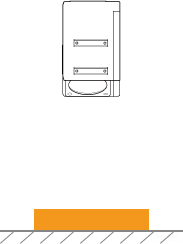
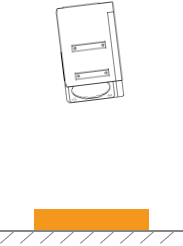
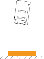
As shown below, the rotation of the laser profiler around the Y-axis make the tilt of the acquired profile differ from the tilt of the actual object.
Not rotated |
Rotated around the Y-axis |
||
Laser profiler |
|
|
|
Acquired profile |
|
|
|


In the scan mode, click Edit to the right of Tilt Correction in the Parameters tab to open the Tilt Correction tool.
Prerequisites
In order to perform tilt correction, the following prerequisites must be satisfied:
-
It is recommended to use a target object whose surface includes flat regions.
-
A relatively complete profile of the flat regions can be acquired. If the profile is incomplete, please refer to Profile Mode and adjust the other parameters first.
-
Keep the target object still relative to the laser profiler, and acquire the profile of the flat regions on the target object.
Instructions
Follow these steps to perform tilt correction:
-
Double-click Edit to the right of Tilt Correction to open the Tilt Correction window.
-
Select the detection areas and drag to adjust their positions. Make sure to satisfy the following criterion while adjusting:
The profile selected by the two detection areas should correspond to two locations on the same flat region of the target object. Please refer to the following example:
Target object 
Detection areas
Correct
Incorrect
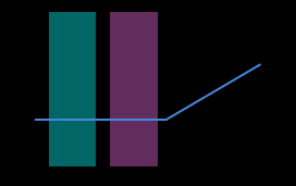
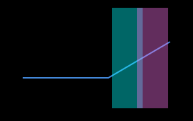
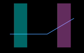
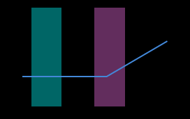
The detection areas can overlap. -
Select the detection areas and drag the handles on them to adjust their widths. Refer to the following criterion while adjusting:
With the above criterion satisfied, the detection area can be as wide as possible to include more data for tilt correction.
-
In Expected tilt angle under Tilt angles, enter the angle that the profile in the detection areas should reach after the correction.
Positive values rotate the profile counterclockwise; negative values rotate the profile clockwise. The range of possible values is -45° to 45°. Example of expected tilt angle
A target object as shown below is placed on a horizontal surface:
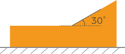
The value that should be entered for Expected tilt angle depends on the positions of the detection areas:
Detection areas Expected tilt angle 0°
30°
-
Click Correct. The green line in the image area on the left represents the profile that has been rotated to Expected tilt angle after tilt correction. Check if this profile satisfies your requirements:
-
If yes, click Apply to apply the tilt correction result and close the window.
-
If no, repeat steps 2 to 5.
-
-
Acquire data again in the profile mode and switch to Profile to check the effect of correction.