Heat-Dissipation Measures for Laser Profiler
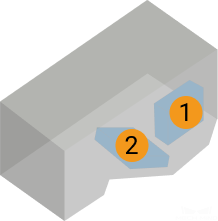
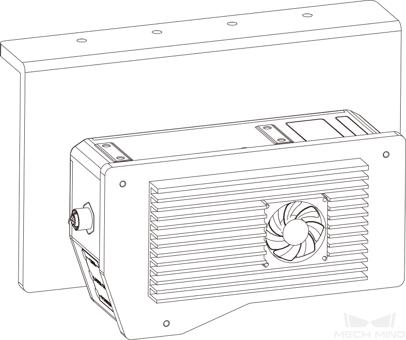
During continuous data acquisition, the data processing unit (① in the figure below) and receiver unit (② in the figure below) inside the laser profiler’s sensor head generate heat. If the sensor head cannot dissipate this heat effectively, the resulting excessively high temperatures may cause it to malfunction.
This topic introduces how to evaluate whether the sensor head can dissipate heat effectively and provides detailed measures for improving the heat-dissipation conditions.
Evaluate Heat-Dissipation Conditions
When any of the following conditions cannot be met, the sensor head cannot dissipate heat effectively through thermal radiation, and you will need to refer to the next section and improve the heat-dissipation conditions.
-
The highest ambient temperature is below 30°C.
-
The laser profiler is in an open space where the air can flow.
-
No heat sources such as high-power or welding devices are present within a 3 m radius of the laser profiler.
-
The sensor head’s internal temperature is below 65°C.
-
The difference between the sensor head’s body temperature and the ambient temperature is below 15°C, or that between the sensor head’s internal temperature and the ambient temperature is below 23°C.
| For the methods of checking the sensor head’s body temperature, sensor head’s internal temperature, and ambient temperature, refer to Check Sensor Head and Ambient Temperature. |
Improve Heat-Dissipation Conditions
Using the appropriate bracket or adding a fan can improve the heat-dissipation efficiency of the sensor head, ensuring that the sensor head’ temperature stays in the appropriate range.
Usually, using the appropriate bracket is enough for effectively improving the heat-dissipation efficiency of the sensor head through thermal conduction. However, in the following situations, a fan must be added to further improve the heat-dissipation efficiency through thermal convection:
-
The highest ambient temperature exceeds 45°C.
-
The sensor head is mounted in a confined space, and the appropriate bracket cannot be used.
-
After the appropriate bracket is used, the sensor head’s internal temperature is still too high, or the difference between the sensor head’s body/internal temperature and the ambient temperature is still too large.
Use Appropriate Bracket
By mounting the sensor head onto the appropriate bracket, the heat-dissipation efficiency of the sensor head can be effectively improved through thermal conduction.
Side Mounting
When mounting the sensor head through its side, using a bracket that satisfies the following requirement can ensure that the sensor head dissipates heat effectively:
-
The bracket is made of metal, and its thickness is no less than 5 mm.
-
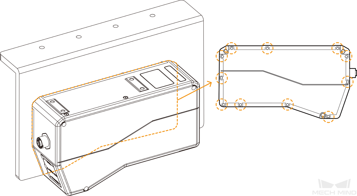
The sensor head’s side with fastening screws (see figure below) is in complete contact with the surface of the bracket.
-
The bracket’s surface in contact with the sensor head is at least as large as the sensor head’s side.
-
The area of the bracket’s surface in contact with air is at least 3 times that of the sensor head’s side surface.
|
If the bracket is made of multiple components, please ensure that:
|
After mounting the sensor head to a bracket satisfying the above requirements, check the sensor head and ambient temperature according to the instructions in Check Sensor Head and Ambient Temperatures to check if the sensor head can dissipate heat effectively.
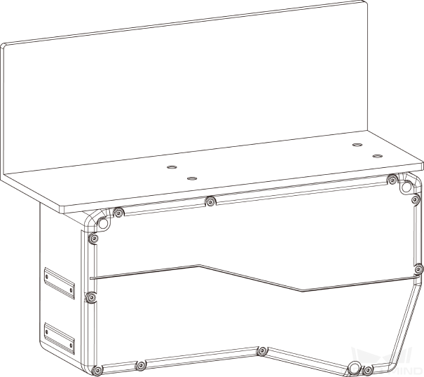
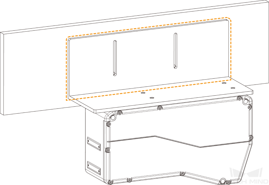
Top Mounting
When mounting the sensor head through its top, using a bracket that satisfies the following requirement can ensure that the sensor head dissipates heat effectively:
-
The bracket is made of metal, and its thickness is no less than 5 mm.
-
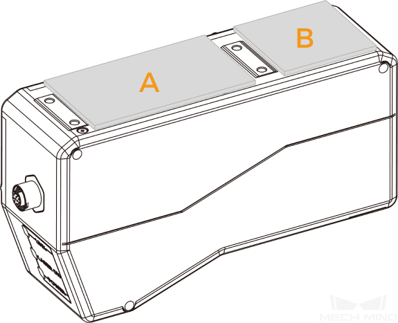
Add silicone thermal pads of the following dimensions between the sensor head and bracket to ensure that the heat generated by the sensor head is conducted to the bracket.
Model
Silicone thermal pads needed
Dimensions (mm)
LNX-7530 and LNX-8030
A
95 × 60
LNX-7580 and LNX-8080
A and B
-
A: 95 × 60
-
B: 50 × 60
LNX-75300 and LNX-8300
A and B
-
A: 98 × 60
-
B: 50 × 60
-
-
The silicone thermal pads are in complete contact with the bracket.
-
The bracket’s surface in contact with the silicone thermal pads should be at least as large as the sensor head’s top surface.
-
The area of the bracket’s surface in contact with air is at least 3 times that of the sensor head’s side surface.
|
If the bracket is made of multiple components, please ensure that:
|
After mounting the sensor head to a bracket satisfying the above requirements, check the sensor head and ambient temperature according to the instructions in Check Sensor Head and Ambient Temperatures to check if the sensor head can dissipate heat effectively.
Add Fan
In the following situations, a fan must be added to further improve the heat-dissipation efficiency through thermal convection:
-
The highest ambient temperature exceeds 45°C.
-
The sensor head is mounted in a confined space, and the appropriate bracket cannot be used.
-
After the appropriate bracket is used, the sensor head’s internal temperature is still too high, or the difference between the sensor head’s body/internal temperature and the ambient temperature is still too large.
The fan should be mounted to a metal plate. The fan and metal plate should satisfy the following requirements:
-
The dimensions of the fan are at least 40 × 40 mm, and the input voltage is 12 V.
-
The metal plate is at least 5 mm thick and mounted to the sensor head’s side.
If the sensor head is mounted through its top, the metal plate should be mounted to the side with the fastening screws.
|
|

After mounting the sensor head to a bracket satisfying the above requirements, check the sensor head and ambient temperature according to the instructions in Check Sensor Head and Ambient Temperatures to check if the sensor head can dissipate heat effectively.
Check Sensor Head and Ambient Temperatures
When the sensor head and ambient temperatures satisfy the following conditions, the sensor head can dissipate heat effectively:
-
The sensor head’s internal temperature is below 65°C.
-
The difference between the sensor head’s body temperature and the ambient temperature is below 15°C, or that between the sensor head’s internal temperature and the ambient temperature is below 23°C.
Follow these methods to check the sensor head’s internal temperature, sensor head’s body temperature, and ambient temperature.
| The sensor head’s internal and body temperatures should be checked after the laser profiler has been acquiring data continuously for at least 1.5 hours. |
-
Check the sensor head’s internal temperature:
-
Connect to laser profiler in Mech-Eye Viewer.
-
On the right, switch to the Acquisition info tab and check the value in the Sensor head row under the Temperatures category.
-
-
Check the sensor head’s body temperature: You can use an infrared thermometer to check the sensor head’s body temperature by following these steps.
-
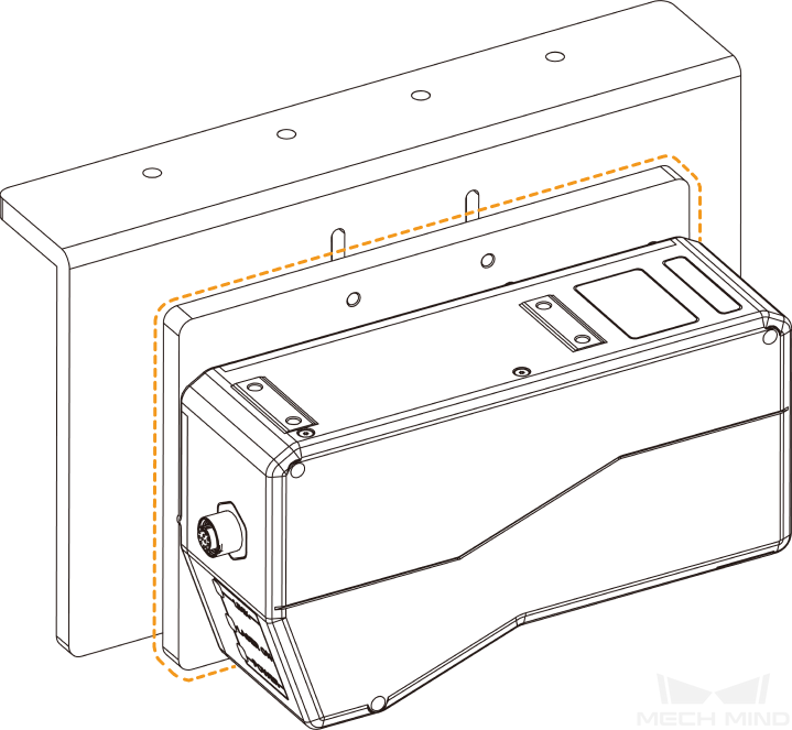
Find the sensor head’s side without the fastening screws, as shown below.
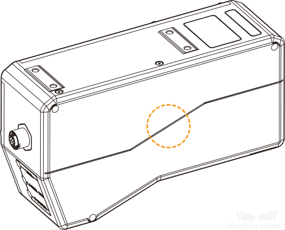
-
Place the sensor part of the infrared thermometer 5 to 10 cm away from the center of this side and measure the temperature.
-
Repeatedly measure the temperature for at least 5 times and take the average as the sensor head’s body temperature.
-
-
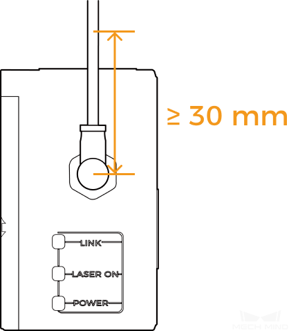
Check the ambient temperature: You can use an infrared thermometer or a mechanical/digital thermometer to check the ambient temperature.
-
Use the infrared thermometer to measure the temperature of the sensor head’s cable as the ambient temperature. The position for measurement should be more than 30 mm away from the center of the M-12 connector. Repeatedly measure the temperature for at least 5 times and take the average.
-
Read the temperature from the mechanical/digital thermometer as the ambient temperature. Place the thermometer 10 to 20 cm away from the sensor head, and make sure that the air inlet is not blocked. Read the temperature after the thermometer is placed still for at least 20 minutes.
Mercury thermometers are not recommended, as they have relatively low accuracy.
-