Hardware User Manual
Safety Instructions
-
To ensure safe use, please do not use the product until you have read this manual and familiarized yourself with the correct usage. Improper use and maintenance may damage the product or cause other hazards. Mech-Mind shall not be liable for any injury or damage brought upon the user or any third party due to improper use and maintenance.
-
Following the instructions and warnings in this manual can lower risks, but cannot eliminate risks. If the product is not used according to this manual, some features may not function normally, or the product may be damaged.
-
Every step has been inspected during the drafting of this manual. Please do not hesitate to contact Mech-Mind if you find any mistakes in the manual or have any questions.
-
The product is to be mounted, connected, used, and maintained by trained adults only. To ensure safe operation, the product should be transported, stored, mounted, connected, used, and maintained properly.
-
Laser is hazardous; please familiarize yourself with the content in Laser Safety before using the product.
Operating Environment
-
Do not use the product in locations with explosion hazards. It is PROHIBITED to place any explosive or flammable substances near the product.
-
Do not expose the product to open fire or high temperature. Do not place the product in fire or crush the product mechanically. Doing so may cause explosion.
-
Do not use the product in environments with extremely high or low temperatures or large temperature variations. The operating temperature of the product is 0–45°C.
-
Please use the product indoors.
-
Please use the product at elevations below 4000 meters.
-
Please install the product in a well-circulated, open place. Do not place the product in humid and dusty locations.
-
Do not install the product under direct sunlight or close to lighting devices. If inevitable, please use shading device to ensure that the product is protected from light interference.
-
Do not install the product in locations subjected to vibration or impact.
-
Do not install the product in locations where water, oil, or other substance may splash onto the product.
Mounting the Product
-
To ensure that the heat from the sensor head is well dissipated, please check the precautions in the Mounting and Connection section carefully.
-
Install the product and cables away from high voltage lines.
-
The sensor head can only be connected to a controller of the same series. Otherwise, the product may be damaged or safety hazards may be induced.
-
Do not supply power to the product until the product is securely mounted and the cables are correctly connected.
Using the Product
-
When using the product for the first time, remove the protective films on the sensor head.
-
Before using, please check the product carefully for damage, signs of water entry, suspicious odor, smoke, loose or damaged bolts, etc., and make sure that the product is in proper working conditions. If any of the above abnormalities occurs, please disconnect the power immediately.
-
After the product is powered on, wait at least 30 minutes before using the product. Otherwise, data quality may be unstable. While adjusting the parameters, do not turn off the power. Doing so may lead to loss of the parameter adjustments.
-
High temperature will age the power cable. Please check the power cable regularly for signs of aging. If the power cable has aged, please contact Mech-Mind to acquire a replacement.
-
The surface of the product may become hot after long time of use. Please use caution to avoid injury.
-
Do not collide with, throw, or drop the product. Strong shock or vibration may lead to damage of the product or malfunction.
-
Do not allow any foreign object, such as metal pieces, dust, paper, and wood chips, to enter the product. Doing do so may lead to fire, electric shock, malfunction, etc.
Using DIN Rail Power Supply
-
Please install the DIN rail power supply inside a control cabinet. Do not install the DIN rail power supply in a place that is difficult to disconnect the power.
-
Do not use the product if the power connector or DIN rail power supply is wet.
-
Do not heat or put the DIN rail power supply and power cable in fire.
-
Please use the specified voltage. Failure to do so may lead to fire or electric shock. It is recommended to use the DIN rail power supply provided by Mech-Mind. If a replacement is required, please use a DIN rail power supply that satisfies relevant safety standards.
-
Use copper conductors only.
Laser Safety
-
Wear laser safety glasses while using the product.
-
The product emits laser beam. Please avoid direct eye exposure to the laser beam. Do not look into the laser beam or the reflected light directly. Do not direct the laser beam at persons. Observing the laser beam may cause visual disturbances such as dazzling and afterimages. Please strictly follow the operational and adjustment requirements in this manual.
-
Do not look into the laser beam with optical instruments (such as telescopes). Doing so may lead to eye injuries.
-
The laser beam must be lower or higher than and never at eye level.
-
Be cautious of the path of the laser beam. Do not enter the areas that the laser beam or reflected light reaches. Do not place reflective objects on the path of the laser beam. Specular or diffuse reflections of the laser beam may result in exposure to the reflected light. Please block the reflections by installing protective enclosure.
-
Failure to use the product according to this manual may lead to exposure to harmful laser radiation.
-
Do not disassemble the product. The product lacks a mechanism to cease laser emission when disassembled.
-
LASER ENERGY - EXPOSURE NEAR APERTURE MAY CAUSE BURNS.
Certifications
The product is compliant with the following standards and assessment requirements. Please note that the certification statuses may be updated. For more information, please contact the local sales agents.
Compliant with the following requirements and standards:
-
European Electromagnetic Compatibility Standards
-
U.S. ANSI C63.4 and 47 CFR PART 15B
-
Canada ICES-003
-
Japan VCCI-CISPR 32:2016
-
South Korea KS C 9832 and KS C 9835
Safety of Laser Products
The laser classification is implemented based on IEC 60825-1:2014 in accordance with the requirements of Laser Notice No. 56 of the FDA (CDRH).
| Model | Wavelength | Max. output power | Laser class |
|---|---|---|---|
LNX-7530 |
405 nm |
7 mW |
Class 2 |
LNX-7580 |
10 mW |
Class 2M |
|
LNX-75300 |
|||
LNX-8030 |
7 mW |
Class 2 |
|
LNX-8080 |
10 mW |
Class 2M |
|
LNX-8300 |


CE

The full text of the EU Declaration of Conformity is available at https://downloads.mech-mind.com/?tab=tab-eu-dec
European Electromagnetic Compatibility Standards:
-
EN 55032:2015+A1:2020+A11:2020
-
EN IEC 61000-3-2:2019+A1:2021
-
EN 61000-3-3:2013+A1:2019+A2:2021
-
EN 55035:2017+A11:2020

All products bearing this symbol are waste electrical and electronic equipment (WEEE as in directive 2012/19/EU) which should not be mixed with unsorted household waste. Instead, you should protect human health and the environment by handing over your waste equipment to a designated collection point for the recycling of waste electrical and electronic equipment, appointed by the government or local authorities. Correct disposal and recycling will help prevent potential negative consequences to the environment and human health. Please contact the local authorities for more information about the location as well as terms and conditions of such collection points.
FCC

NOTE: This equipment has been tested and found to comply with the limits for a Class A digital device, pursuant to part 15 of the FCC Rules. These limits are designed to provide reasonable protection against harmful interference when the equipment is operated in a commercial environment. This equipment generates, uses, and can radiate radio frequency energy and, if not installed and used in accordance with the instruction manual, may cause harmful interference to radio communications. Operation of this equipment in a residential area is likely to cause harmful interference in which case the user will be required to correct the interference at his own expense.
This device complies with part 15 of the FCC Rules. Operation is subject to the following two conditions: (1) This device may not cause harmful interference, and (2) this device must accept any interference received, including interference that may cause undesired operation of the device.
“Le présent appareil est conforme aux CNR d’Industrie Canada applicables aux appareils radio exempts de licence. L’exploitation est autorisée aux deux conditions suivantes : (1) l’appareil ne doit pas produire de brouillage, et (2) l’utilisateur de l’appareil doit accepter tout brouillage radioélectrique subi, même si le brouillage est susceptible d’en compromettre le fonctionnement.”

Package Contents
Sensor Head and Accessories
Sensor Head |
|
||||
|---|---|---|---|---|---|
Sensor-head-to-controller cable
|
|
||||
User manual |
|
||||
Accessory bag |
M5 × 8 bolts (Qty: 4) |
M5 × 70 bolts (Qty: 3) |
Φ5 washers (Qty: 3) |
Zip ties (Qty: 50) |
4 mm hex key (Qty: 1) |
|
|
|
|
|
|


Controller and Accessories
Controller |
|
|
|---|---|---|
Controller DC power cable
|
|
|
Controller Ethernet cable
|
|
|
Encoder cable
|
|
|
Accessory bag |
M5 × 8 bolts (Qty: 4) |
Flat screwdriver (Qty: 1) |
|
|
|


|
Functional Diagrams
This product consists of a sensor head and controller.
|
|
Sensor head |
Controller |
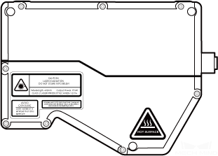
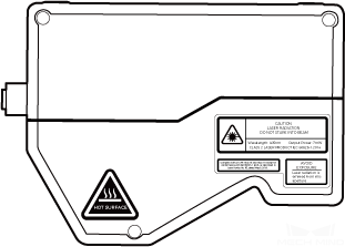
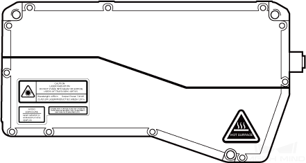
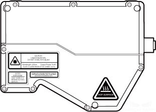
Sensor Head

| No. | Name | Function |
|---|---|---|
① |
Laser emitter |
Emits laser light. |
② |
Receiver unit |
Receives the laser light reflected by the target surface. |
③ |
Controller port |
Used to connect to the controller. See Controller Port for details. |
④ |
LINK indicator light |
Off: not connected to network |
Blinking green: data in transmission (2.5 Gbps) |
||
Blinking yellow: data in transmission (10/100/1000 Mbps) |
||
⑤ |
LASER ON indicator light |
Off: laser light not emitted |
Solid on: laser light being emitted |
||
⑥ |
POWER indicator light |
Off: not connected to power |
Solid green: normal voltage |
||
⑦ |
Shading device mounting hole |
Used to mount shading device onto the sensor head. |
Controller

| No. | Name | Function |
|---|---|---|
① |
Sensor head port |
Used to connect to the sensor head. See Sensor Head Port for details. |
② |
RUN indicator light |
On: data acquisition in progress |
Off: no ongoing data acquisition |
||
③ |
PWR indicator light |
Solid green: normal voltage |
Off: abnormal voltage or not connected to power |
||
④ |
ERR indicator light |
Blinking: malfunctioning |
Off: operating normally |
||
⑤ |
Power terminals |
24V: +24 VDC input |
0V: 0 VDC input |
||
PE: grounding |
||
⑥ |
Input signal terminals |
See Input Signal Terminals for details. |
⑦ |
Output signal terminals |
See Output Signal Terminals for details. |
⑧ |
Encoder signal terminals |
Used to connect to the encoder. See Encoder Signal Terminals for details. |
⑨ |
Network indicator light |
Blinking: data transmission in progress |
Solid: no ongoing data transmission |
||
⑩ |
RJ45 Ethernet port |
Used to connect the RJ45 connector of the Ethernet cable. |
Mounting and Connection

|
Mount the Sensor Head
Before mounting, please check the following precautions:
-
The shape of the target object may produce blind spots in the measurement range. Please evaluate the effect of blind spots on scanning before mounting the sensor head. The laser light of this product is emitted almost in parallel, and therefore blind spots are rarely present.

-
Make sure that the laser light reflected by the target object is not blocked and can reach the receiver unit.

-
Stray light is produced if the laser light is reflected by surrounding objects such as walls. Please evaluate the effect of stray light on scanning before mounting the sensor head.

-
To ensure that the heat from the sensor head is well dissipated, please mount it onto a metal bracket, and make sure that the area of the bracket’s surface in contact with air is at least 3 times that of the sensor head’s side surface.
For more details on heat-dissipation measures, refer to Heat-Dissipation Measures for Laser Profiler.


Mount the Controller
Before mounting, please check the following precautions:
-
Leave at least 50 mm of space above the controller and on both sides. Leave at least 90 mm of space in front of the side where the ports and connectors are located.

-
For controllers mounted side by side, leave at least 50 mm of space between and above controllers.

As shown below, place four M5 × 8 bolts in the holes, and then use an open-end wrench to tighten the nuts.

Connect Sensor Head and Controller
Connect the right-angle connector of the sensor-head-to-controller cable to the controller port on the sensor head and the straight connector to the sensor head port on the controller.

-
When inserting the connectors, align the bump in the connector with the notch in the port.
-
Tighten the nut. The recommended tightening torque is 0.7 N·m. A gap of about 2 mm remains after the nut is fully tightened.

|
Please fasten the cables properly to avoid damaging the cables or connectors due to strain. |
Connect Controller and IPC
Insert one end of the controller Ethernet cable into the RJ45 Ethernet port on the controller and the other end into the RJ45 Ethernet port on the IPC.

|
Connect Controller and DIN Rail Power Supply

|
Connect Controller DC Power Cable to Controller
-
Use the flat screwdriver to loosen the screws above the power terminals on the controller.

-
Insert the wire with the +V label into the 24V terminal, the wire with the -V label into the 0V terminal, and the wire with the PE label into the PE terminal (
 ).
).
-
Use the flat screwdriver to tighten the screws on the terminals. The recommended tightening torque is 0.2 N·m.

Connect Cables to DIN Rail Power Supply

-
Use the flat screwdriver to loosen the screws on the terminals of the DIN rail power supply.
-
Connect the controller DC power cable: Insert the wire with the +V label into one of the +V terminals, the wire with the -V label into one of the -V terminals, and the wire with the PE label into the ground terminal (
). -
Connect the AC power cable: Insert the live wire into the L input terminal on the DIN rail power supply, the neutral wire into the N input terminal, and the ground wire into the ground terminal (
). -
Use the flat screwdriver to tighten the screws on the terminals.
|
Connect Wires to Signal Terminals
-
Select the terminal into which the wire should be inserted and use the flat screwdriver to press down the button above/below it.

-
Insert the wire into the terminal, and then remove the flat screwdriver.

-
The stripped part of the wire should be about 0.7 cm. If the stripped part is too short, the wiring might fail.
-
If the strands of the wire are loose, please twist the strands together and then insert the wire into the terminal.
-
-
Gently pull the wire. The wire should not be pulled out if inserted properly. If the wire is pulled out, insert it again.
Do not pull the wire too strongly. Doing so may pull out the wire forcibly and damage the stripped part.
If you need to pull out the wire, press down the button above/below the terminal with the flat screwdriver, and then pull out the wire.
Signal Circuit Diagrams
Input Signals
The output signals of an external device such as PLC can be inputted to the input signal terminals of the controller. The following is the circuit diagram of the input signals of the controller:

Logical HIGH voltage |
22–26 V |
Logical LOW voltage |
< 5 V |
Min. current |
6 mA |
Max. current |
50 mA |
Max. frequency |
1 kHz |
Isolation voltage |
2500 Vrms (min) |


Output Signals
The output signals of the controller can be inputted to the input signal terminals of an external device. The following is the circuit diagram of the output signals of the controller:

Logical LOW output voltage |
< 0.3 V |
Max. output current |
20 mA |
Leakage current in closed state |
< 0.5 μA |
Insulation resistance |
> 1011 Ω |
Max. frequency |
1 kHz |
Isolation voltage |
2500 Vrms (min) |

Single-Ended Encoder
The output signals of a single-ended encoder can be connected to the encoder signal terminals of the connector. The following is the circuit diagram of the single-ended encoder signals of the controller:

Connection Examples
-
Connect an encoder with the NPN open collector output to the encoder signal terminals of the controller:

[1] The supplied voltage in the above example is 12 V.
-
Connect an encoder with the PNP open collector output to the encoder signal terminals of the controller:

[1] The supplied voltage in the above example is 12 V.
Differential Encoder
The output signals of a differential encoder can be connected to the encoder signal terminals of the connector. The following is the circuit diagram of the differential encoder signals of the controller:

|
When connecting the encoder, please use shielded cables suitable for RS-422 signals. |

Maintenance
Cleaning
Disconnect the product from power before cleaning. When cleaning the surface of the product, please use a clean soft cloth to gently wipe off the dust and debris. When cleaning the windows, to avoid scratching, you can use a clean, soft lint-free cloth with lens cleaner or glass cleaner to carefully wipe the windows.
|
Storage
The sensor head is rated as IP67. The enclosure of the sensor head can prevent dust and water from entering and affecting the functions of the sensor head. Please avoid soaking the product in water or placing it outdoors for an extended period of time. When not using, please store the product in an indoor, dry, cool, and well ventilated place. The storage temperature of the product is -30–70°C.
|
Disclaimer
It is strongly recommended to use the power supply and cables provided by Mech-Mind to ensure compliance with the safety and EMC standards. Mech-Mind shall not be liable for any issues caused by using the power supply and cables provided by a third party.
Trademark and Legal Statement
Mech-Mind and Mech-Mind series logos including ![]() are registered trademarks of Mech-Mind Robotics Technologies Co., Ltd. and other related entities.
are registered trademarks of Mech-Mind Robotics Technologies Co., Ltd. and other related entities.
© Copyright 2026, Mech-Mind Robotics Technologies Co., Ltd.
Unless authorized in writing in advance by Mech-Mind Robotics Technologies Co., Ltd. (“Mech-Mind”), no part of the trademarks shall be used, reproduced, modified, transmitted, transcribed, or used or sold with other products as a bundle by any entity or individual in any form for any reason.
Any infringement of Mech-Mind’s trademark rights will be punished in accordance with the law.
Mech-Mind reserves all rights regarding this user manual. According to copyright laws, unless authorized by Mech-Mind, this user manual shall not be reproduced, modified, or issued in part or in its entirety by any entity or individual. Users who purchased and use the product may download, print, or copy the user manual for personal use or use inside the belonging organization. Unless authorized by Mech-Mind, the contents of the user manual may not be used for any other purposes.