Parameters of ULTRA M-GL
This topic introduces the parameters of ULTRA M-GL based on the parameter categories. By adjusting these parameters, the quality of 2D images, depth maps, and point clouds can be improved.
Overview
The parameter categories that affect the quality of the 2D image, depth map, and point cloud are as follows:
| Parameter category | 2D image | Depth map | Point cloud |
|---|---|---|---|
|
|||
(1) |
|
|
|
|
|||
|
|
||
|
|
(1) The Gain and Light Brightness parameters in the 3D parameter category affects the brightness of the 2D image (depth source). For details, refer to Flash Acquisition Mode.
The goal of adjusting the parameters is to obtain high-quality 2D images, depth maps, and point clouds that meet the following standards:
-
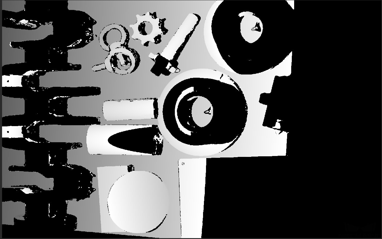
The 2D image should not be too bright or too dark, and the surface features of the target object should be clearly visible in the image.
If you are using a color camera, and the color of the image differ significantly from that of the objects, you can adjust the white balance setting. For detailed instructions, please refer to Adjust White Balance. -
In the depth map and point cloud, the needed data should be complete.
Determine which part of the data is needed according to your actual needs. For example, if you need to pick metal bowls with opening facing up by the rim, usually you only need to make sure that the data of the bowl rims is complete.
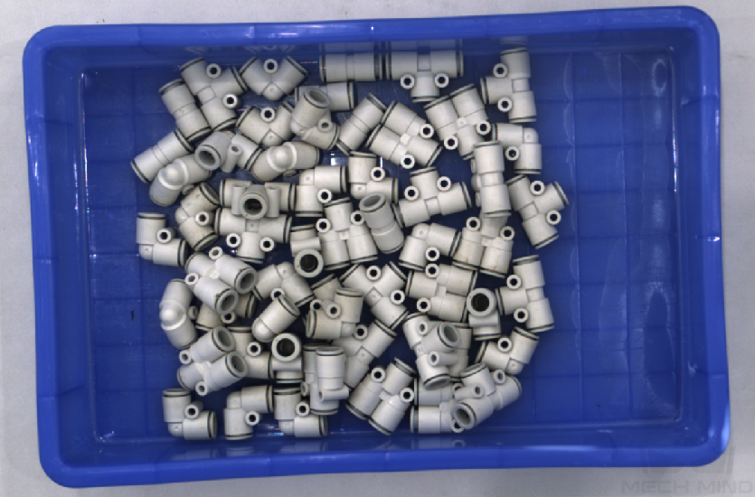
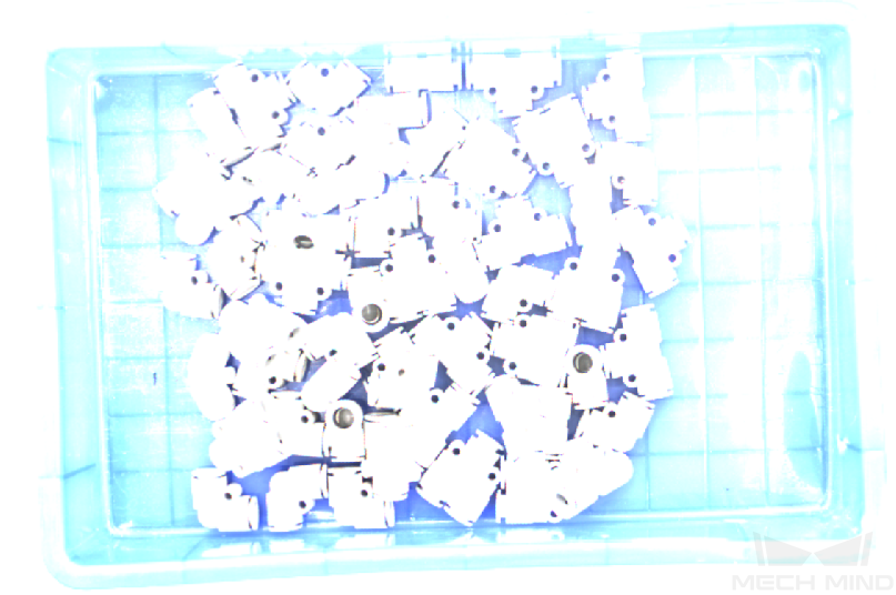
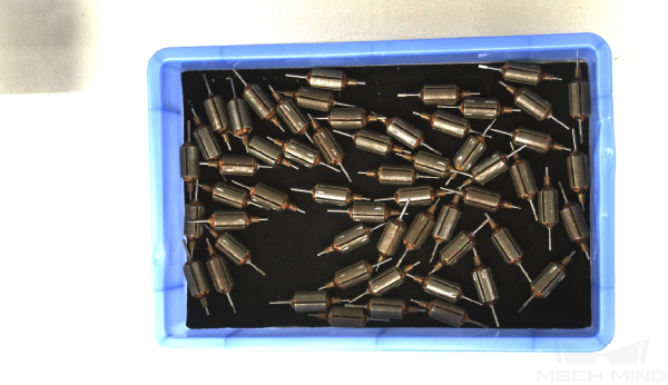
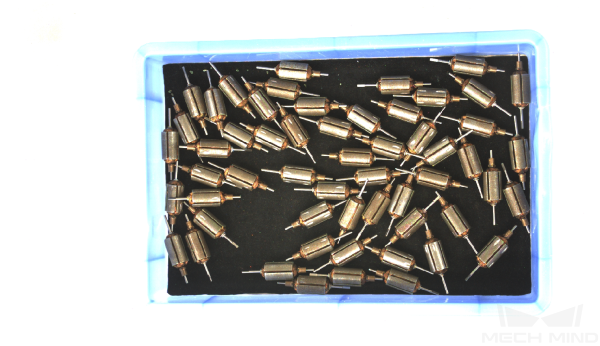
This model provides two types of 2D images: 2D image (texture) and 2D image (depth source). The usage of each type is as follows:
| Type | Usage Scenario |
|---|---|
2D image (texture) |
Texture the point cloud |
2D image (depth source) |
Check intrinsic parameters |
Set ROI |
|
Perform hand-eye calibration |
1. 2D Parameters
The parameters in this category affect the quality of the 2D images. The category includes the 2D image (texture) and 2D image (depth source) subcategories.
1.1. 2D image (texture)
The parameters in the 2D image(texture) subcategory affect the quality of the 2D image (texture).
1.1.1. Exposure Mode
Description |
Sets the exposure mode for capturing the 2D image (texture). |
|---|---|
Visibility |
Beginner, Expert, Guru |
Values |
|
Instruction |
After selecting different options, different parameters are displayed in the 2D Parameters category for adjustment:
|
1.1.2. Timed: Exposure Time
Description |
Affects the brightness of the 2D image (texture).
|
|---|---|
Visibility |
Beginner, Expert, Guru |
Values |
0.1 to 999 ms |
Instructions |
Adjust this parameter based on the image quality. The image should not be too bright or too dark, and the surface features of the target object should be clearly visible in the image.
|
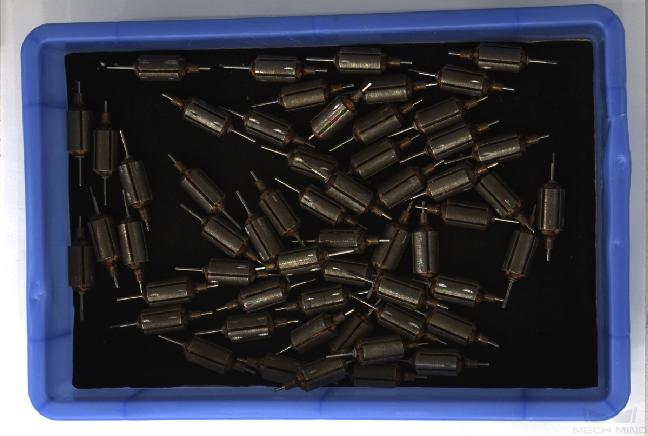
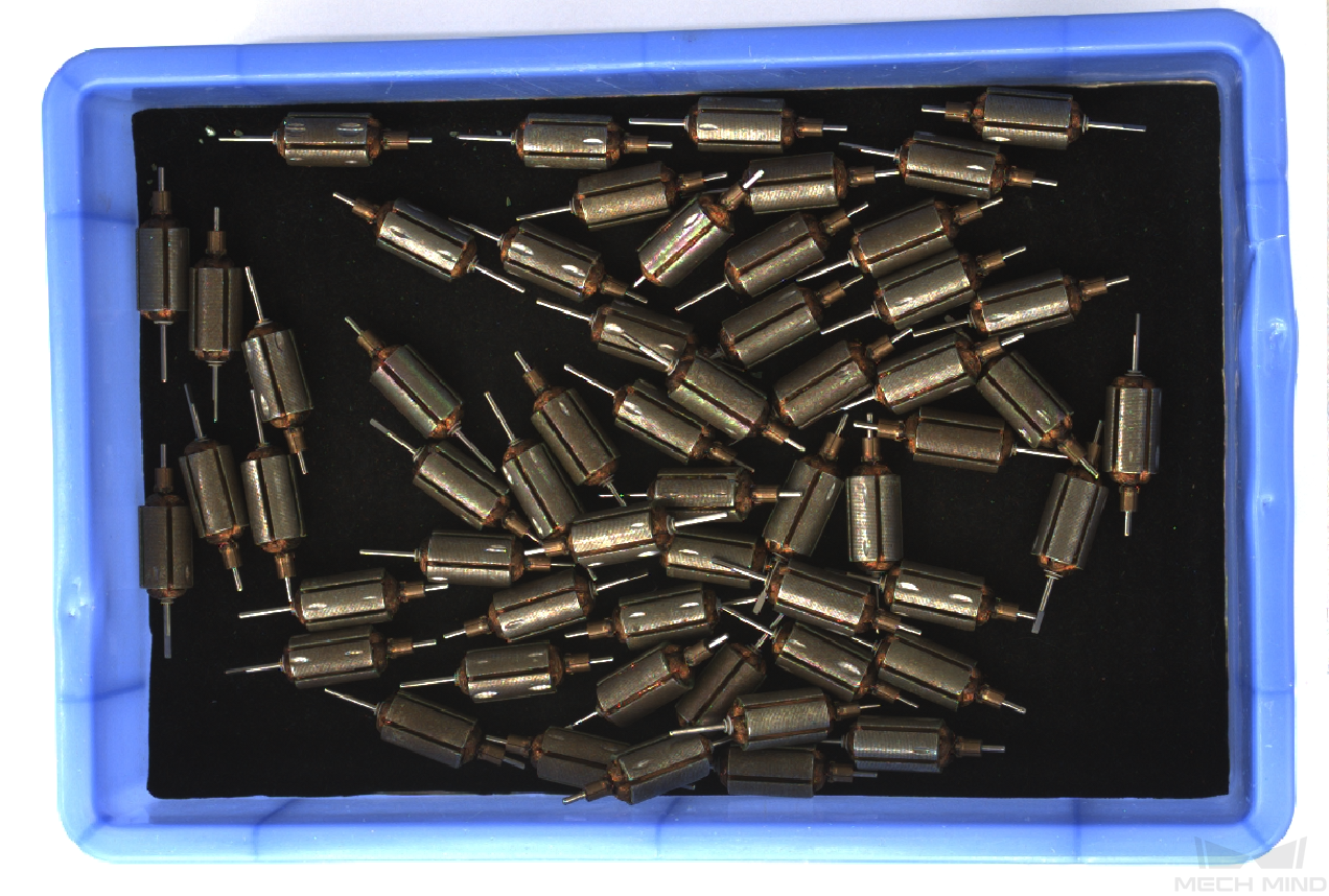
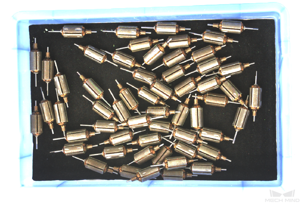
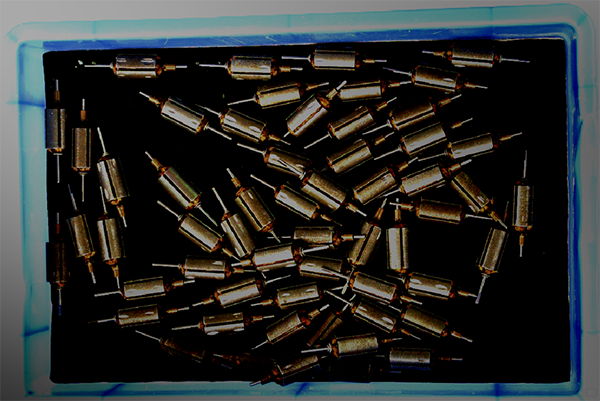
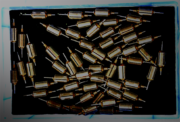
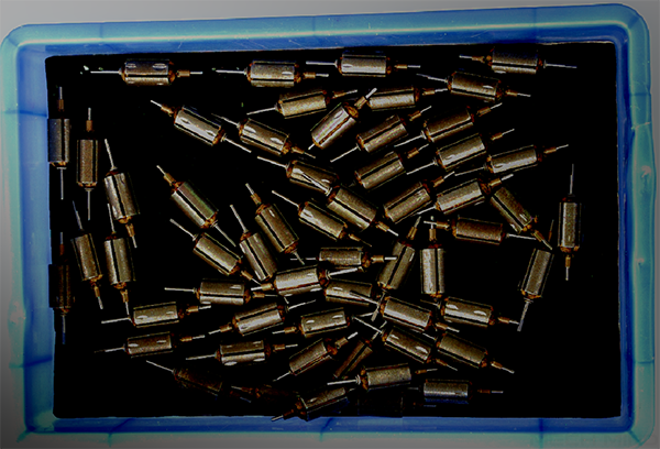
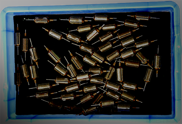
Images obtained with different Exposure Time values (all other conditions identical):
| 5 ms | 90 ms | 500 ms |
|---|---|---|
|
|
|
1.1.3. Auto: Gray Value
Description |
Affects the brightness of the 2D image (texture). Increase the value if the image is too dark and decrease if too bright. |
|---|---|
Visibility |
Beginner, Expert, Guru |
Values |
0 to 255 |
Instruction |
N/A |
Images obtained with different Gray Value values (all other conditions identical):
| 50 | 100 | 150 |
|---|---|---|
|
|
|
| The Gray Value of a monochrome image is equivalent to the image brightness; the Gray Value of a color image is equivalent to the brightness of each color channel. |
1.1.4. Auto: Auto-Exposure ROI
Description |
|
|---|---|
Visibility |
Beginner, Expert, Guru |
Values |
N/A |
Instruction |
For detailed instructions, refer to Set Auto-Exposure ROI below. |
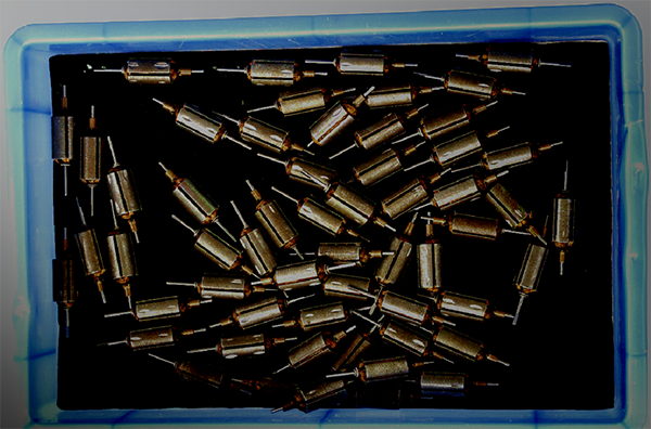
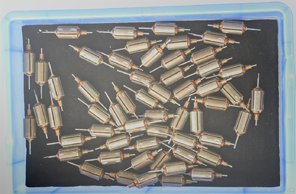
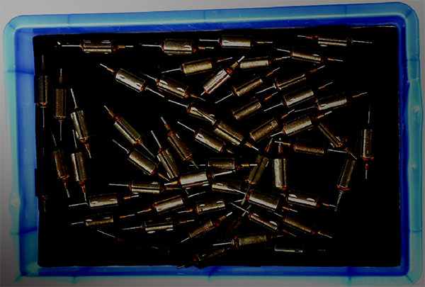
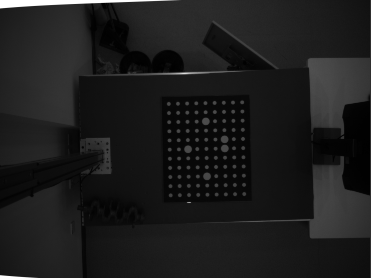
Images obtained with different Auto-Exposure ROI values (all other conditions identical):
| Auto-exposure ROI | 2D image (texture) |
|---|---|
|
|
|
|
|
|
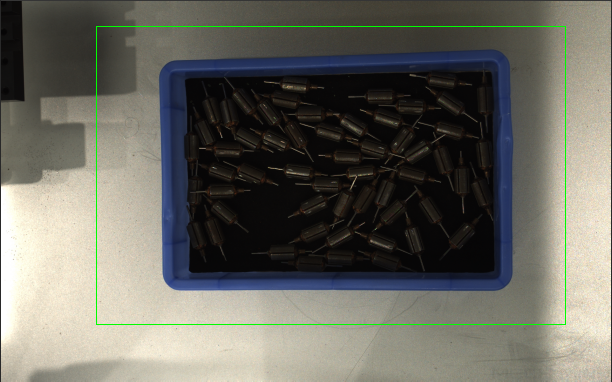

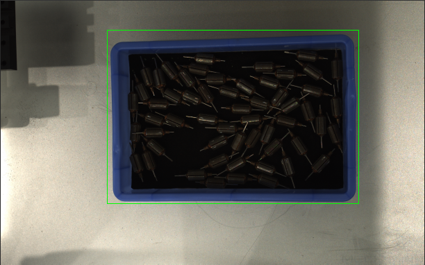
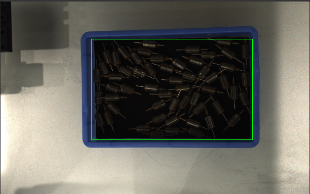
Set Auto-Exposure ROI
-
Click Edit to the right of Auto-Exposure ROI to open the Set ROI window.
-
Select and adjust the ROI on the left. Drag the selection box to move it. Drag the handles on the box to adjust the box size.
-
Click Apply to apply the set auto-exposure ROI.
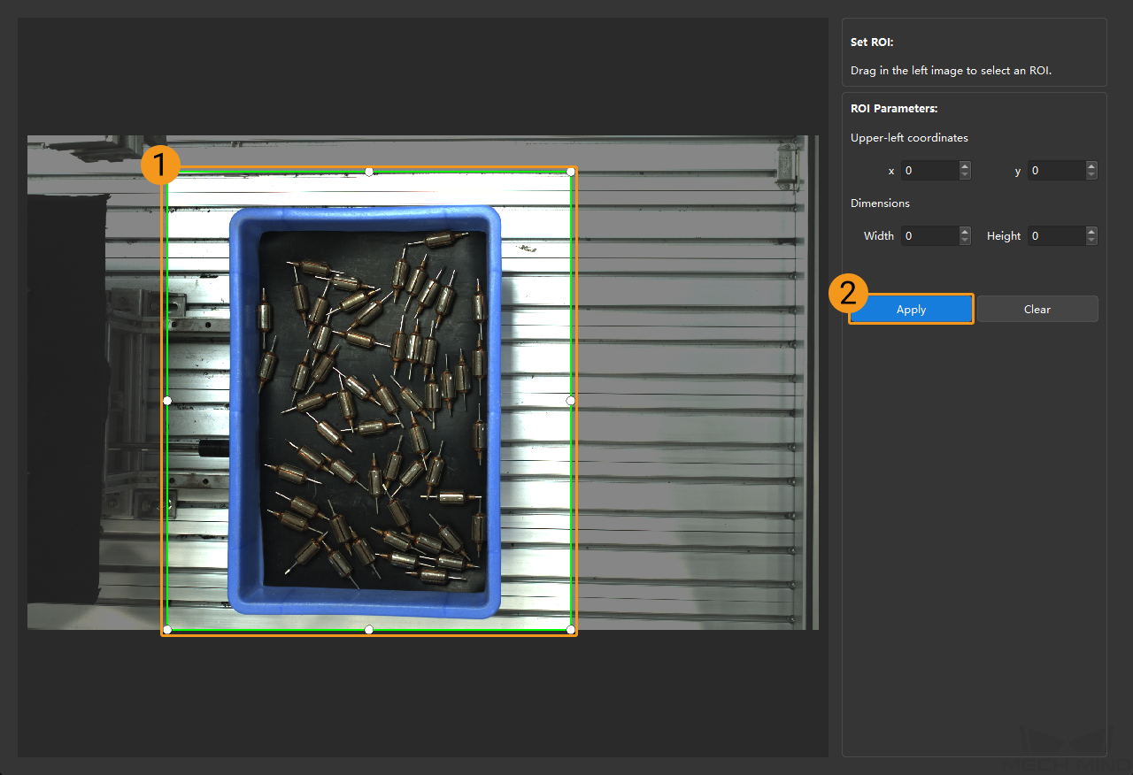
Click Clear to remove the current auto-exposure ROI. -
Acquire data again and view the image to check the result of automatic exposure adjustment.
1.1.5. HDR: Tone Mapping
Description |
This function can make the image look more natural. Enable this function if the 2D image (texture) appears very different from the actual objects. |
|---|---|
Visibility |
Beginner, Expert, Guru |
Values |
Tone Mapping toggle switch:
|
Images obtained with Tone Mapping off or on (all other conditions identical):
| Off | On |
|---|---|
|
|
1.1.6. HDR: Exposure Sequence
Description |
Sets multiple exposure times, and the captured images are merged to generate a 2D image that retains more details in the highlights and shadows. |
||
|---|---|---|---|
Visibility |
Beginner, Expert, Guru |
||
Values |
N/A |
||
Instructions |
|
Images acquired with single exposure times (all other conditions identical):
| 500 ms | 700 ms | 900 ms |
|---|---|---|
|
|
|
Images acquired with different exposure sequences consisting of the above exposure times (all other conditions identical):
| 500ms & 900ms | 500 ms & 700 ms & 900 ms |
|---|---|
|
|
1.1.7. Gain
Parameters |
This parameter increases the brightness of the 2D image (texture), but might amplify noise. |
|---|---|
Visibility |
Expert, Guru |
Values |
0 to 16 dB |
Instruction |
When the expected brightness cannot be reached by adjusting Exposure Time, adjust this parameter. |
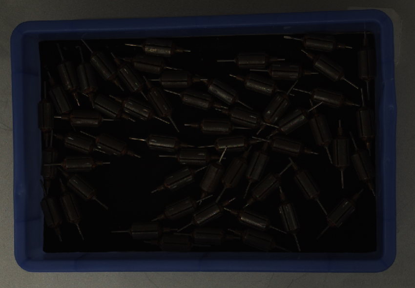
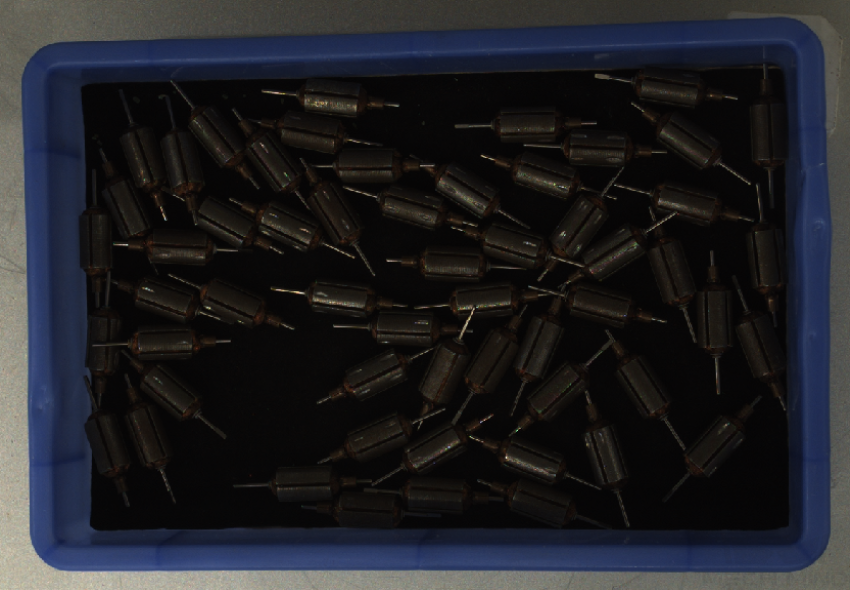
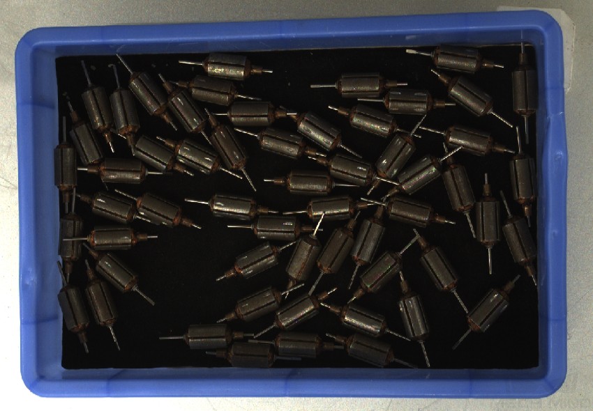
2D images (texture) obtained with different Gain values (all other conditions identical):
| 0 | 5 | 10 |
|---|---|---|
|
|
|
1.2. 2D image (depth source)
The parameters in the 2D image(depth source) subcategory affect the quality of the 2D image (depth source).
1.2.1. Exposure Mode
Parameter Description |
Sets the exposure mode for capturing the 2D images (depth source). |
|---|---|
Visibility |
Beginner, Expert, Guru |
Values |
|
Instruction |
After selecting different options, different parameters are displayed in the 2D Image (Depth Source) category for adjustment:
|
1.2.2. Timed: Exposure Time
Description |
Affects the brightness of the 2D image (depth source)).
|
|---|---|
Visibility |
Beginner, Expert, Guru |
Values |
0.1 to 999 ms |
Instructions |
Adjust this parameter based on the image quality. The image should not be too bright or too dark, and the surface features of the target object should be clearly visible in the image.
|
Images obtained with different Exposure Time values (all other conditions identical):
| 10 ms | 40 ms | 80 ms |
|---|---|---|
|
|
|

1.2.3. Flash: Flash Acquisition Mode
Parameter Description |
Selects the mode for acquiring 2D images (depth source) when adding supplemental light with the projector. For detailed descriptions, refer to 2D Flash Exposure Mode. |
|---|---|
Visibility |
Beginner, Expert, Guru |
Values |
|
Instruction |
Adjust this parameter based on the actual needs for the data acquisition speed and the image refresh rate during continuous acquisition.
|
1.2.4. Flash: Flash Exposure Time
Description |
Sets the exposure time for capturing 2D images (depth source) when the value of Flash Acquisition Mode is set to Responsive. |
|---|---|
Visibility |
Beginner, Expert, Guru |
Values |
0.1–99ms |
Instruction |
Long exposure time is usually used in dark environments, and short exposure time is usually used in bright environment. |
1.2.5. Flash: Light Brightness
Parameter Description |
Sets the brightness of the structured light projected by the projector when Flash Acquisition Mode is set to Responsive. |
|---|---|
Visibility |
Expert, Guru |
Values |
20–100% |
Instruction |
None |
1.2.6. Gain
Parameter Description |
This parameter increases the brightness of the 2D image (depth source), but might amplify noise. |
|---|---|
Visibility |
Expert, Guru |
Values |
0–16 dB |
Instruction |
Adjust this parameter when the expected brightness cannot be reached by adjusting Exposure Time, Flash Exposure Time or Light Brightness. |
2D images (depth source) obtained with different Gain values (all other conditions identical):
| 0 | 5 | 10 | |
|---|---|---|---|
2D image (depth source) |
|
|
|
2. 3D Parameters
The parameters in this category affect the images used for calculating depth data, thus affecting the quality of the depth map and point cloud.
Use Exposure Assistant can obtain the recommended exposure parameter values. Click Auto Set to the right of 3D Parameters to open Exposure Assistant.
2.1. Exposure Multiplier
Description |
Set the number of Exposure Time. |
|---|---|
Visibility |
Beginner, Expert, Guru |
Values |
1–2 |
Instruction |
|
2.1.1. Exposure Time Extension
Parameter Description |
When Fringe Coding Mode is set to Translucent or Reflective, this parameter can be enabled to extend the upper limit of Exposure Time from 30.0 ms to 99.0 ms, meeting the requirements of special acquisition scenarios involving target objects such as black sheet metal parts and black reflective plastics. |
|---|---|
Visibility |
Guru |
Values |
Disabled by default. |
Instruction |
This parameter is unavailable when Fringe Coding Mode is set to Fast or Accurate. |
2.1.2. Exposure Time
Parameter Description |
Sets the exposure time for acquiring depth data.
|
||
|---|---|---|---|
Visibility |
Beginner, Expert, Guru |
||
Values |
|
||
Instruction |
|
2.1.3. Gain
Parameter Description |
This parameter increases the brightness of the depth map, but might amplify noise.
|
||
|---|---|---|---|
Visibility |
Expert, Guru |
||
Values |
0–16 dB |
||
Instruction |
When the expected brightness cannot be reached by adjusting Exposure Time, adjust this parameter. |
Depth maps obtained with different Gain values (all other conditions identical):
| 0 | 5 | 10 | |
|---|---|---|---|
Depth map |
|
|
|
2.2. Projector
2.2.1. Fringe Coding Mode
Parameter Description |
Selects the pattern of the structured light to be projected. |
|---|---|
Visibility |
Expert, Guru |
Values |
|
Instruction |
Adjust this parameter according to the type of the target object and your actual needs for data quality and data acquisition speed. |
|
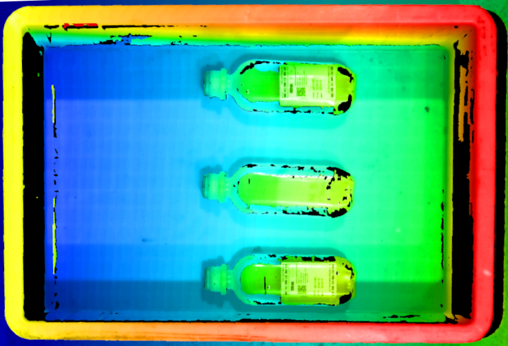
The Translucent option can greatly improve the quality of depth data for translucent objects. The following are some typical suitable objects:
-
IV fluid bags
-
Plastic test tubes (frosted surface)
-
Plastic packaging (bags, bottles, cans, boxes, etc.)
Meanwhile, the improving effect of the Translucent option has the following limit:
-
For highly transparent objects (such as clear glass test tubes), the improving effect is not significant.
-
For largely curved areas on the objects, the improving effect is not significant.
-
When translucent objects overlap each other, the improving effect is not significant.
-
When the background is light-colored or highly reflective, the improving effect is not significant.
-
When the ambient light is strong or varies frequently, the improving effect is not significant.
-
When using a camera whose 2D image is monochrome, because the projected structured light is blue, if the translucent objects contain blue objects inside, the improving effect is not significant.
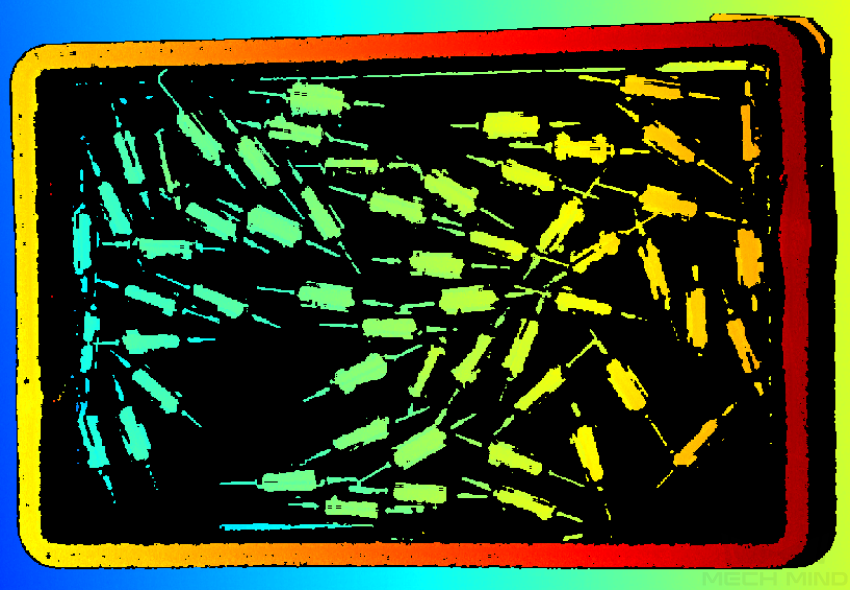
-
When the target object is opaque and non-reflective, the point clouds obtained with Fringe Coding Mode set to Accurate and Fast are as follows (all other conditions identical):
Accurate Fast 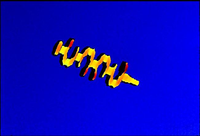
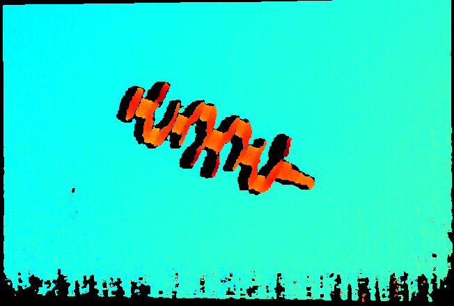
-
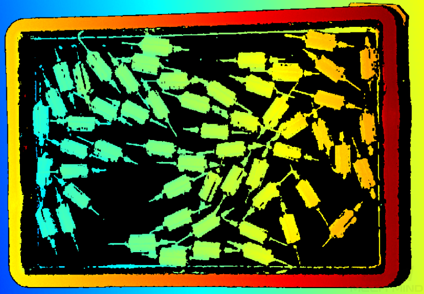
When the target object is translucent, the point clouds obtained with Fringe Coding Mode set to Accurate and Translucent are as follows (all other conditions identical):
Accurate Translucent 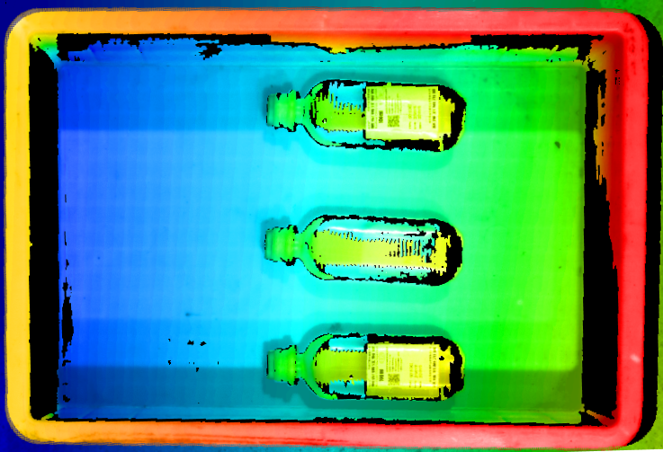
-
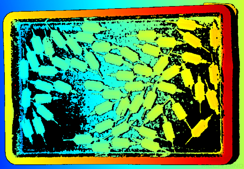
When the target object is reflective, the point clouds obtained with Fringe Coding Mode set to Accurate and Reflective are as follows (all other conditions identical):
Accurate Reflective 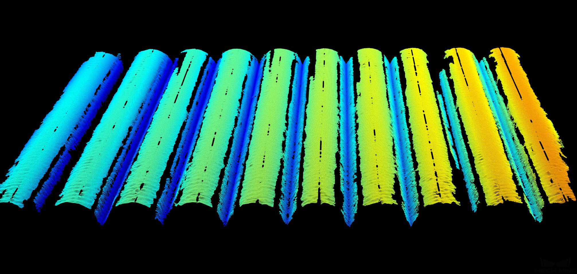
2.2.1.1. Reflective: Processing Mode
Parameter Description |
Selects the data processing mode for the Reflective fringe coding mode. |
|---|---|
Visibility |
Expert, Guru |
Values |
|
Instruction |
Adjust this parameter according to your actual needs for data quality and data acquisition speed. |
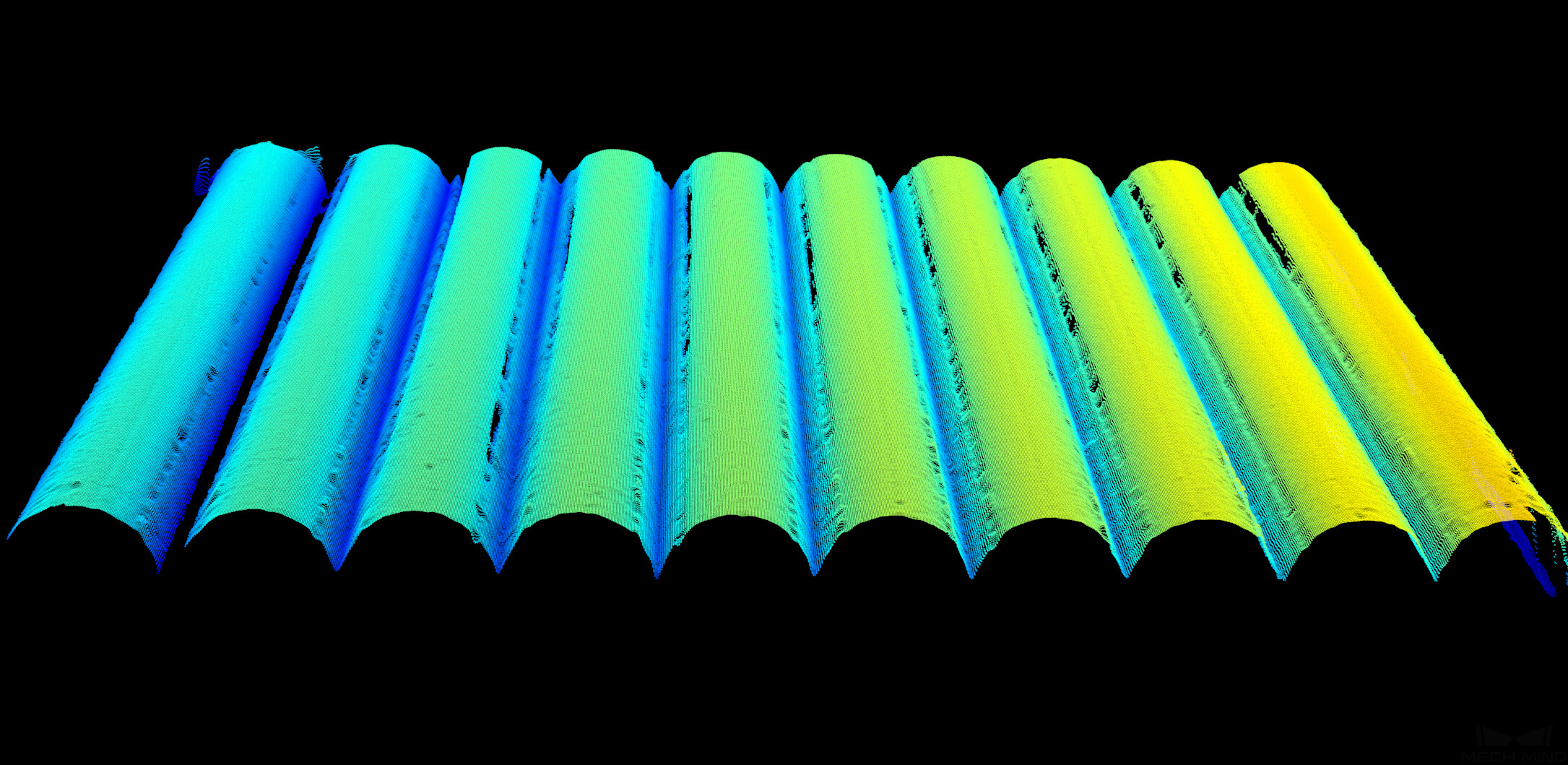
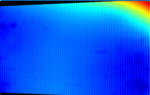
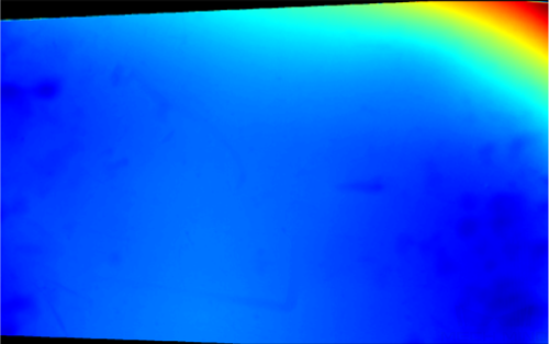
2.2.2. Anti-Flicker Mode
Description |
Flicker refers to the rapid and periodical change in the intensity of artificial light. This phenomenon can cause fluctuations in the depth data. Such fluctuations can be reduced by adjusting the projection frequency of the structured light. |
|---|---|
Visibility |
Expert, Guru |
Values |
|
Instructions |
Please select the option that corresponds to the frequency of the power supply in your location. The AC frequency in most countries is 50Hz. The AC frequency in the U.S. and some Asian countries is 60Hz. |
|
Anti-Flicker Mode is unavailable when Fringe Coding Mode in the 3D Parameters category is set to Translucent or Reflective. |
Depth maps obtained with Anti-Flicker Mode off or on (all other conditions identical):
| Off | On |
|---|---|
|
|
2.2.3. Pulse Flicker Suppression
Parameter Description |
When enabled, suppresses the impact of short-duration, low-frequency, rapid, and sudden pulse-like flicker on data acquisition, improving acquisition stability. |
|---|---|
Visibility |
Expert, Guru |
Values |
Disabled by default. |
Instruction |
Pulse Flicker Suppression is unavailable when Fringe Coding Mode in the 3D Parameters category is set to Accurate. |
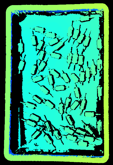
3. Point Cloud Processing
3.1. False Point Removal
Parameter Description |
Removes false points from the point cloud. False points are incorrect point cloud data caused by factors such as occlusion of the field of view. |
|---|---|
Visibility |
Expert, Guru |
Values |
|
Values |
Disabled by default. |
3.2. Normal Outlier Removal
Parameter Description |
Removes outliers caused by abrupt depth changes, such as large flying points near the bin walls. |
|---|---|
Visibility |
Expert, Guru |
Values |
|
Values |
Disabled by default. |
3.3. Outlier Removal
Parameter Description |
Removes the outliers in the point cloud. Outliers are clustered points away from the object point cloud. |
|---|---|
Visibility |
Beginner, Expert, Guru |
Values |
0–10 |
Instruction |
|
3.4. Noise Removal
Description |
This parameter removes the noise in the point cloud, thus reducing the impact on the precision and accuracy of subsequent calculation. Noise is the scattered points close to the object surface. |
|---|---|
Visibility |
Expert, Guru |
Values |
|
Instructions |
|
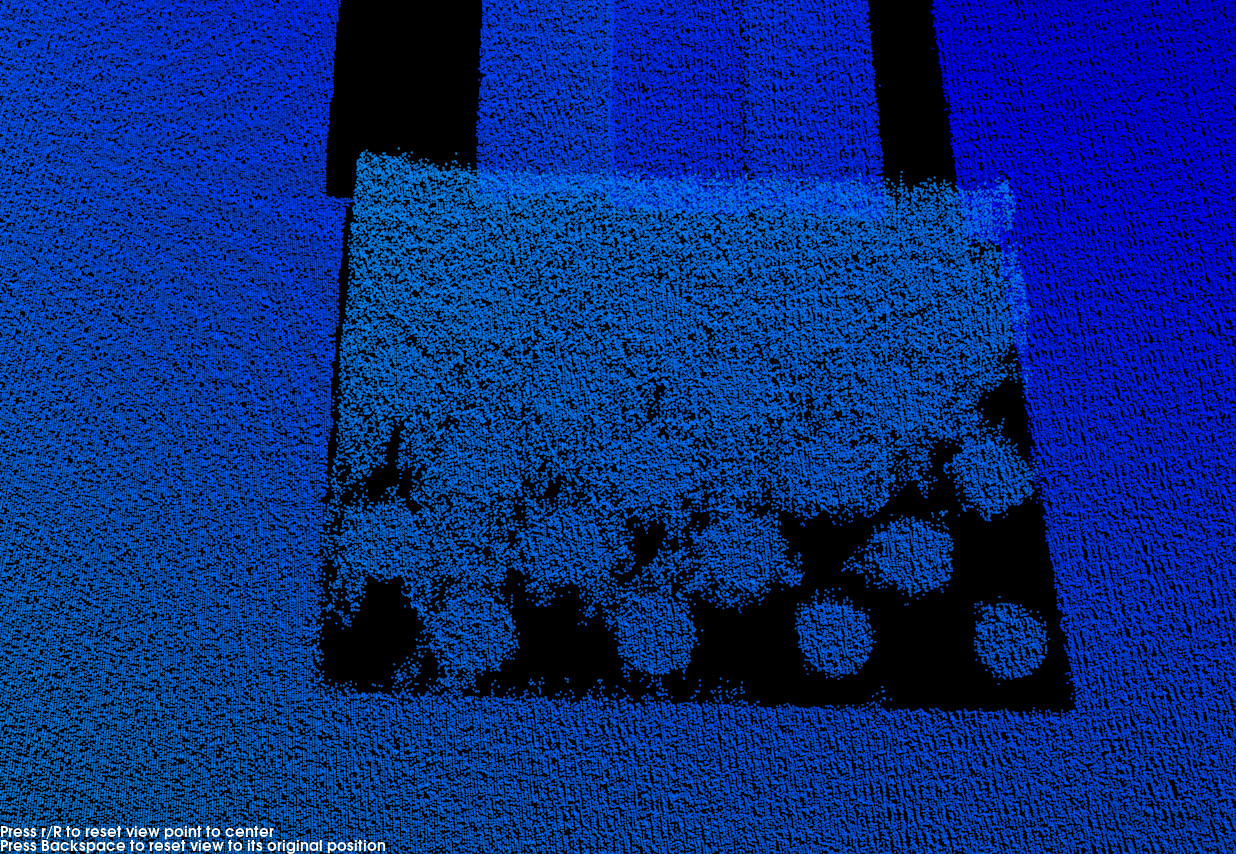
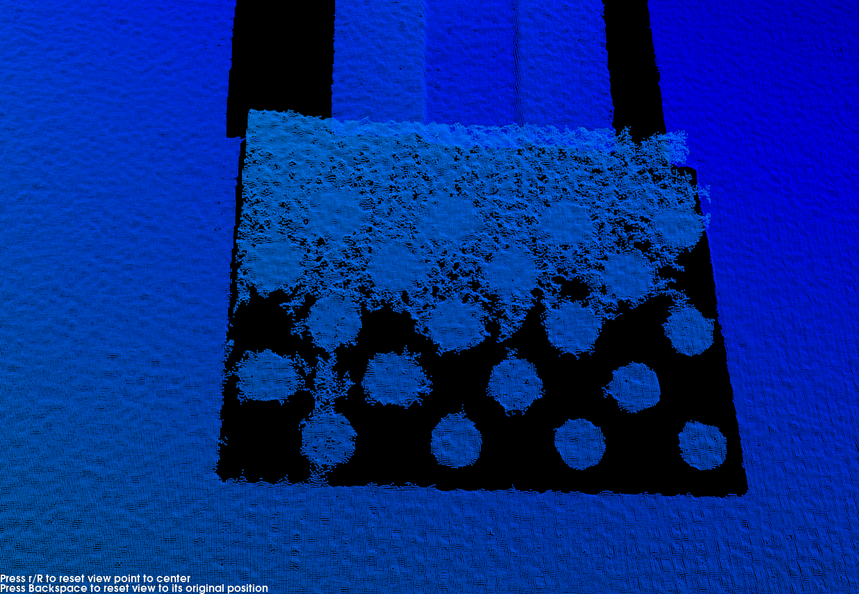
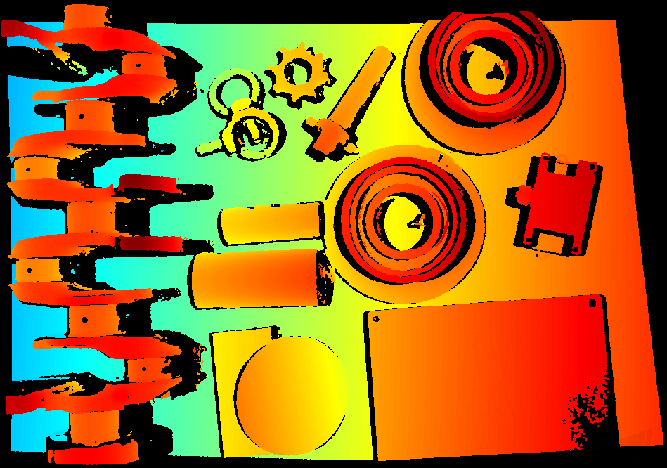
Point clouds obtained with different Noise Removal values (all other conditions identical):
| Off | Weak |
|---|---|
|
|
Normal |
Strong |
|
|

| If this function removes the needed object features, please reduce the intensity. However, more noise will be retained. |
3.5. Surface Smoothing
Description |
This parameter reduces the depth fluctuation in the point cloud and improve its resemblance to the actual object surface. |
|---|---|
Visibility |
Beginner, Expert, Guru |
Values |
|
Instructions |
|
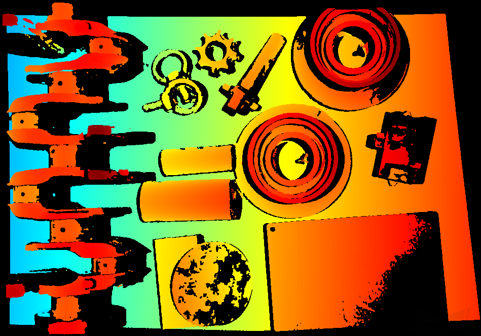
Point clouds obtained with different Surface Smoothing values (all other conditions identical):
| Off | Weak |
|---|---|
|
|
Normal |
Strong |
|
|
3.6. Gap Filling
Parameter Description |
Fills in the gaps in the point cloud so that the object’s surface features are more complete. |
|---|---|
Visibility |
Expert, Guru |
Values |
|
Instruction |
Adjust this parameter based on the amount of missing points in the point cloud. |
3.7. Stripe Contrast Threshold
Description |
This parameter is used to remove noise in the point cloud. Adjust this parameter if the level of noise in the point cloud is still high after adjusting Outlier Removal and Noise Removal. |
|---|---|
Visibility |
Beginner, Expert, Guru |
Values |
1 to 100 |
Instructions |
|
Point clouds obtained with different Stripe Contrast Threshold values (all other conditions identical):
| 3 | 15 | 30 |
|---|---|---|
|
|
|

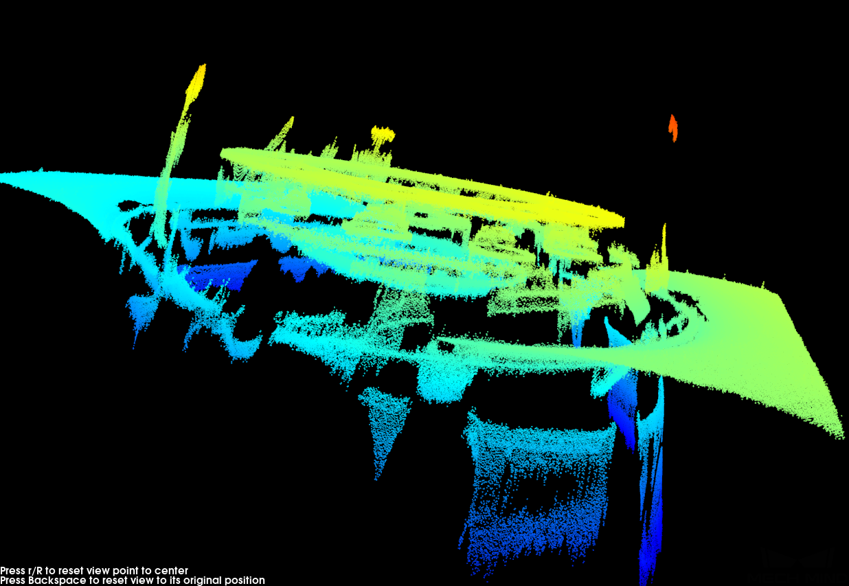
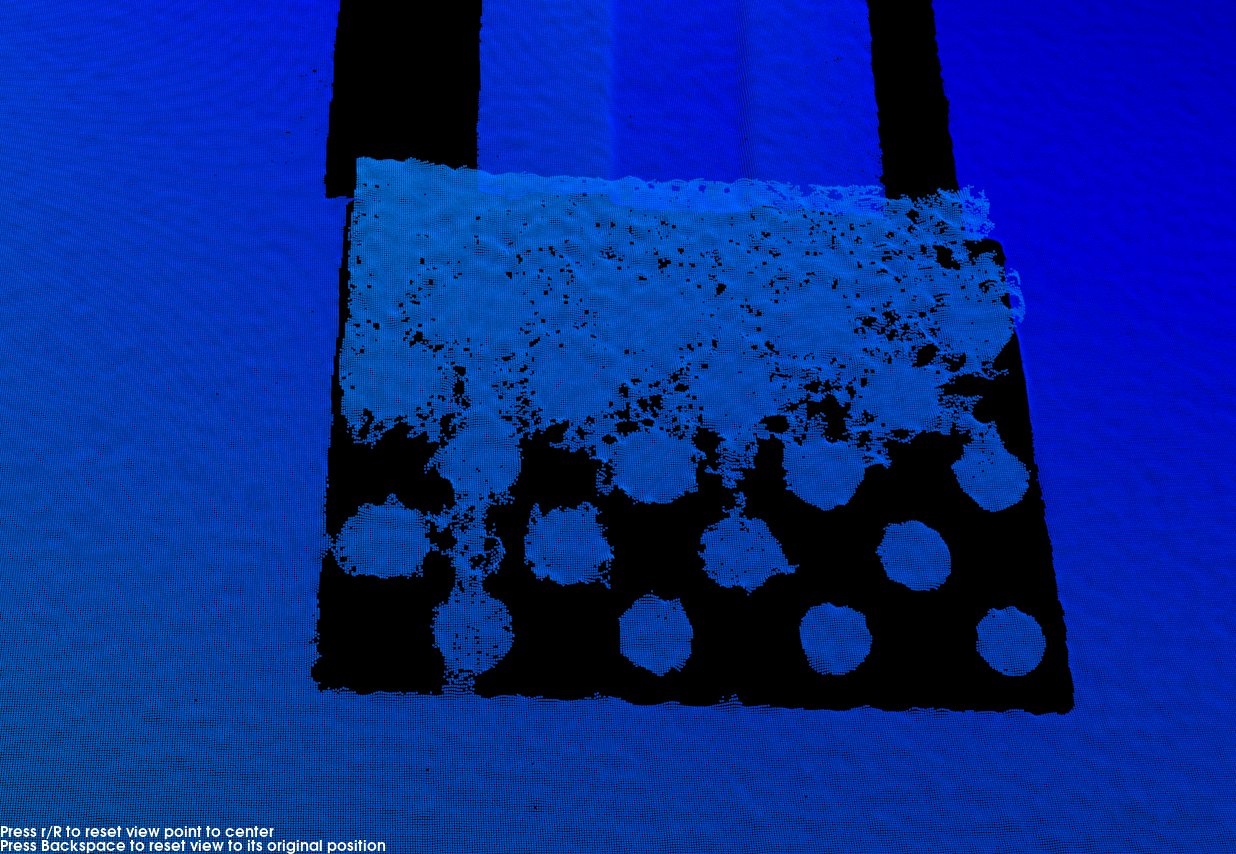
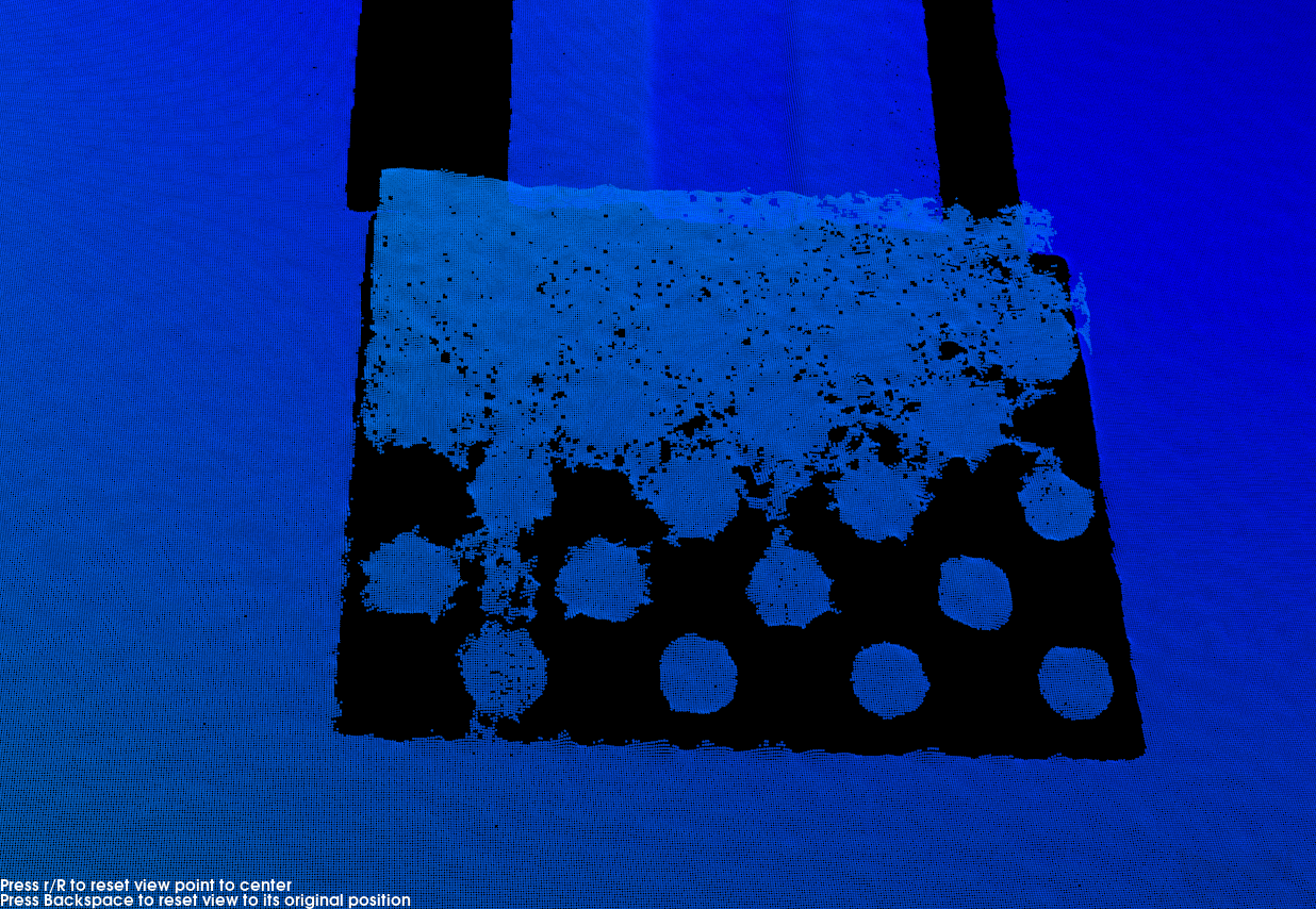
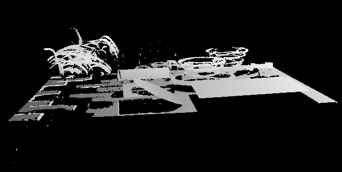
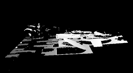
3.8. Edge Artifact Removal
Description |
This parameter removes artifacts in the point cloud of the outer contour regions or geometric bends of an object. Artifacts are erroneous data that do not actually exist at the object’s edges. However, they are generated in the point cloud due to field of view occlusion or other factors. |
|---|---|
Visibility |
Expert, Guru |
Values |
Disabled by default. |
Instruction |
|
|
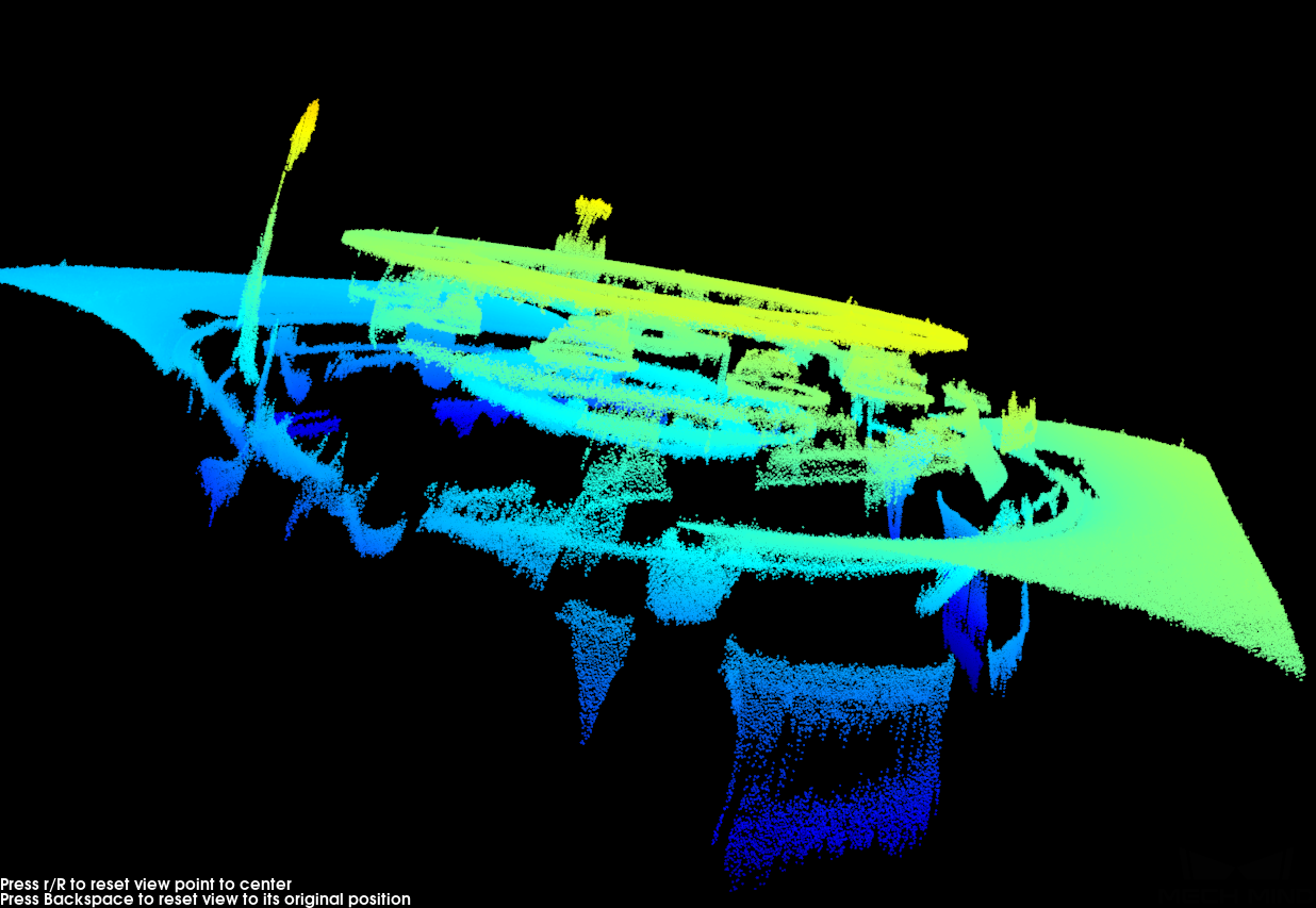
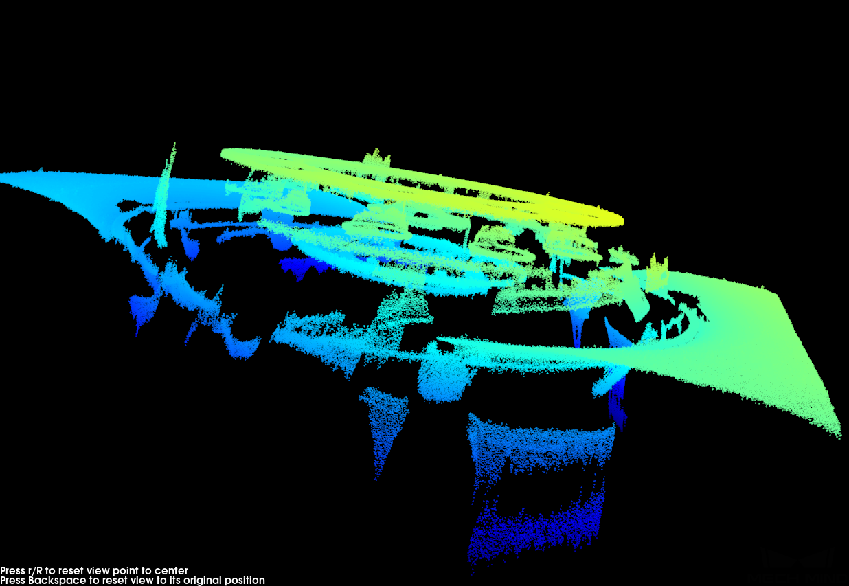
In this image, the yellow points are artifacts.
|
Point clouds when Edge Artifact Removal is disabled or enabled:
| Disabled | Enabled |
|---|---|
|
|
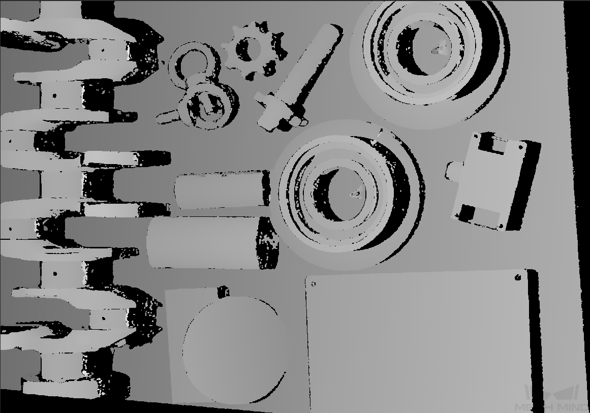
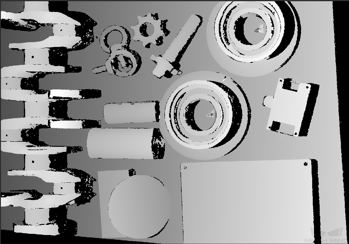
4. Depth Range
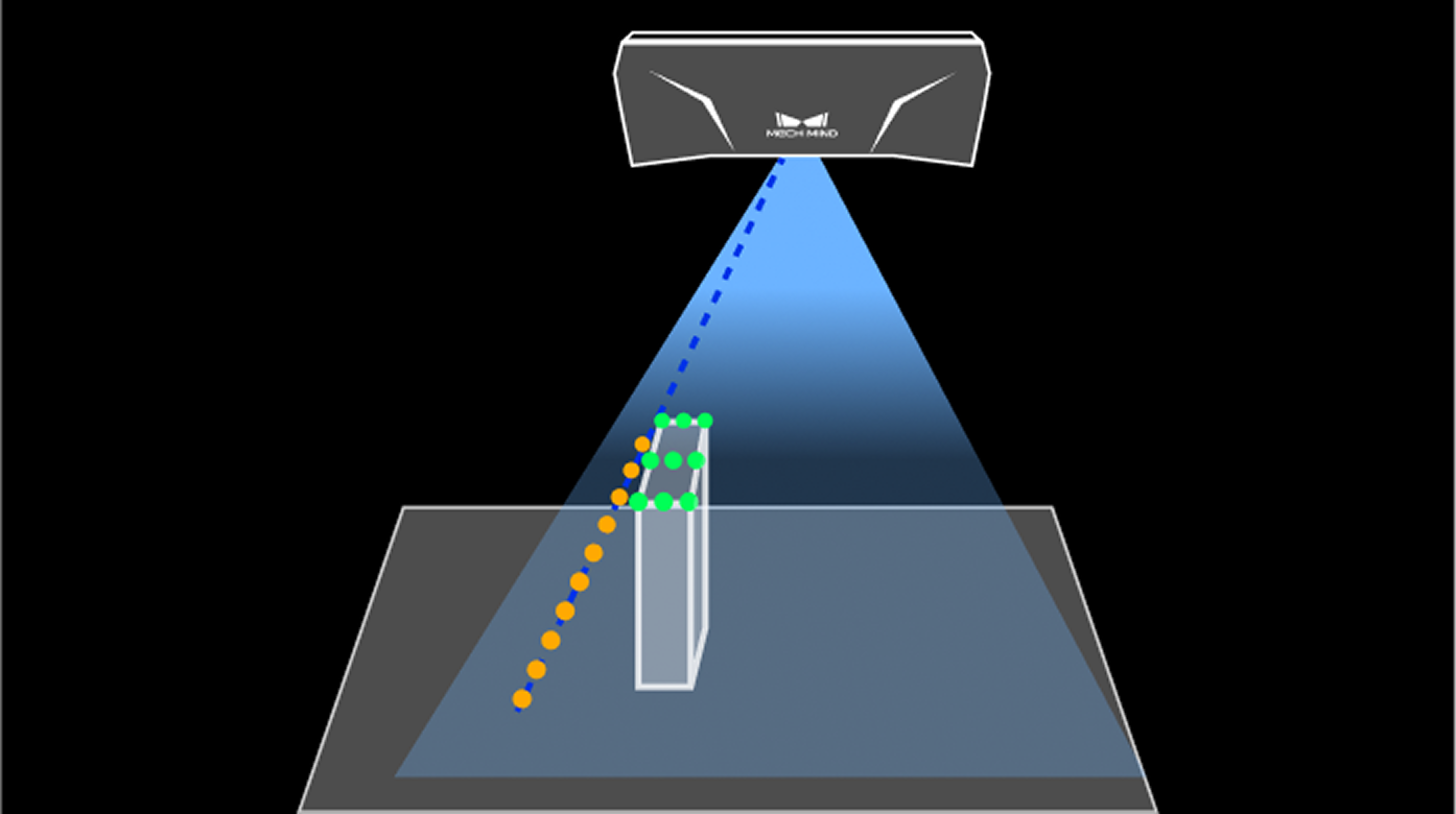
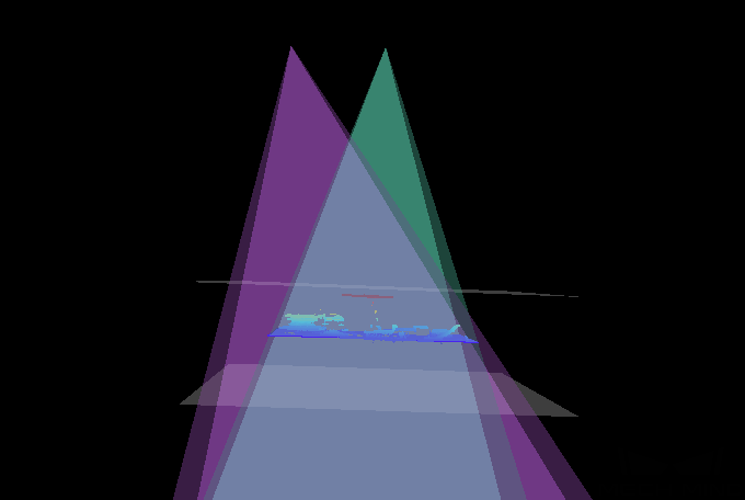
Description |
Set a Z-direction ROI for the depth map and point cloud. Depth Range can be set within the camera working distance, and the data outside the range is removed from the depth map and point cloud. |
|---|---|
Visibility |
Beginner, Expert, Guru |
Instructions |
|
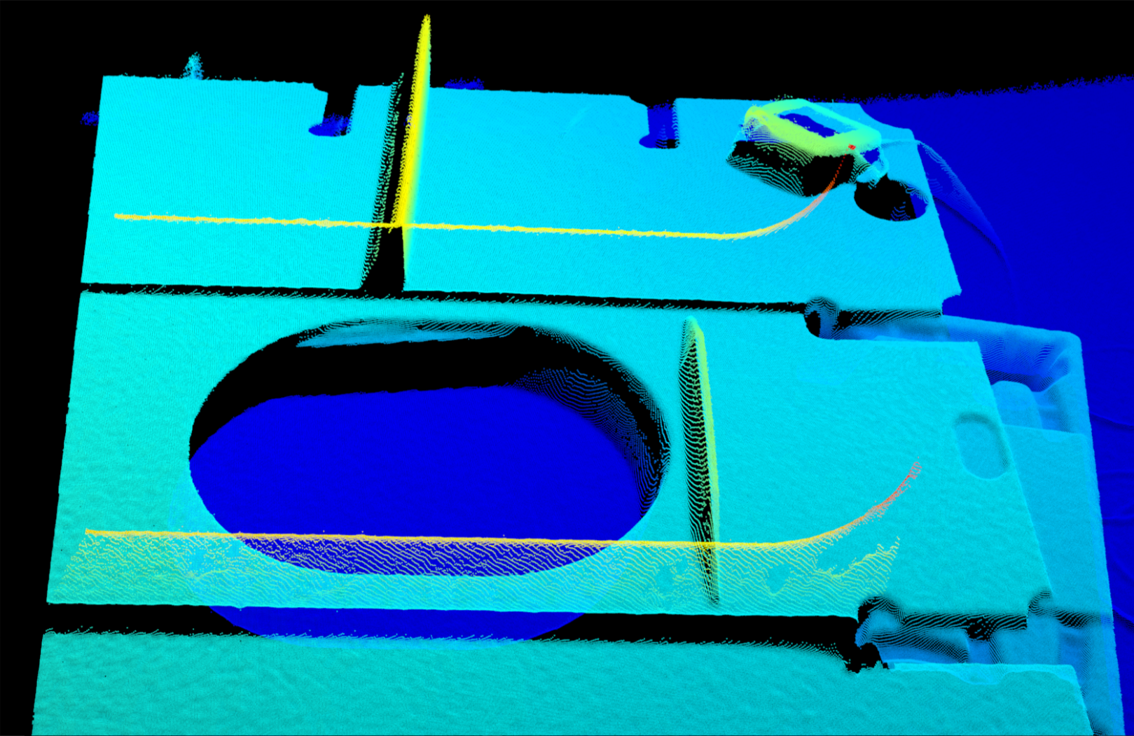
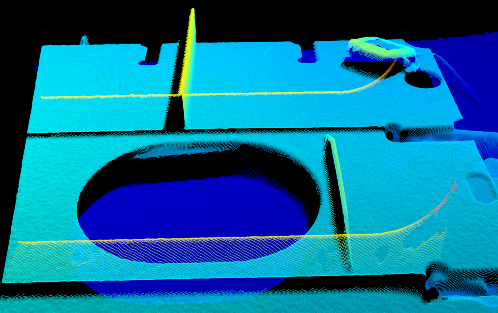
The same point cloud with different Depth Range values (all other conditions identical):
| Too large | Appropriate | Too small |
|---|---|---|
|
|
|
|
|
|
Set Depth Range
Follow these steps to adjust Depth Range:
-
Click Edit on the right of Depth Range to open the Set Depth Range window.
-
Click Refresh point cloud at the top of the right panel to obtain the newest point cloud.
-
Adjust the position of the point cloud: adjust the position until you can see the two gray rectangles that represents the upper and lower limits of Depth Range.
-
Adjust the depth range: drag the handles on the slider to adjust Depth Range roughly. Then, enter specific values on the right to fine-tune Depth Range.
Judge if the depth range is appropriate: All needed object features are located between the two gray rectangles, and most noise and outliers are located outside. -
Click Save to save the depth range settings.
|
5. Region of interest
Description |
Set the ROI on the XY plane for the depth map and point cloud. Points outside the selected region are removed. |
|---|---|
Visibility |
Beginner, Expert, Guru |
Values |
N/A |
Instructions |
For detailed instructions, refer to Set ROI below. |
Set ROI
-
Click Edit on the right of ROI to open the Set ROI window.
-
Select and adjust the ROI on the left. Drag the selection box to move it. Drag the handles on the box to adjust the box size.
-
Click Apply to apply the set ROI.

-
Click Clear to remove the current ROI.
-
The interface displays the 2D image (depth source). If the image is too dark or too bright, please adjust Exposure Mode in the 2D Image (Depth Source) subcategory.
-
-
Acquire data again and view the depth map or point cloud to check the result of setting the ROI.