Getting Started
This topic will guide you through the entire process from checking package contents to using Mech-Eye Viewer to capture images.
|
The diagrams are for illustrative purposes only. The actual product may differ. |
1. Check Package Contents
-
Make sure that the camera package is intact when you receive it.
-
Check contents according to the “packing list” in the package to ensure that no devices or accessories are missing or damaged.
| The table below is for reference only. Please take the “packing list” in the package as the final. |
|
|

|

|
|
|

|

|
|
|
M4 × 8 socket head cap screws |
M5 × 8 socket head cap screws |
M8 × 20 socket head cap screws |
M8 × 20 T-bolts |

|
|
M8 nuts |
M8 flange nuts |

|
|
M8 washers |
Ø6 × 10 dowel pins |
Cable tie mount (Qty: 1) |
Zip ties (Qty: 50) |

|
|
Hex keys (Qty: 3) |
Calibration board (UHP-140-GL only) |

|

|
|
Besides the camera package, you may also receive the following optional accessories (if purchased):
|

2. Check Ports and Indicator Lights
Please refer to the following figures and tables and check the functions of the ports and indicator lights on the camera.
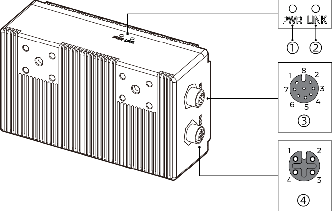
2.1. DEEP-GL, LSR S-GL, LSR L-GL, LSR XL-GL, PRO S-GL, PRO M-GL, and UHP-140-GL

No. |
Name |
Function |
|
|---|---|---|---|
① |
DC 24V port |
1: GND |
3: 24 VDC |
2: GND |
4: 24 VDC |
||
② |
ETH port |
1: MD3_P |
5: MD1_P |
2: MD2_N |
6: MD0_N |
||
3: MD2_P |
7: MD3_N |
||
4: MD0_P |
8: MD1_N |
||
③ |
PWR indicator light |
Off: not connected to power |
|
Green: normal voltage |
|||
Solid yellow: voltage lower than 16 V or higher than 28 V |
|||
Solid red: voltage lower than 12 V |
|||
④ |
LINK indicator light |
Off: not connected to network |
|
Solid or blinking green: connected to network |
|||
⑤ |
SYS indicator light |
Off: camera not started |
|
Solid green: camera starting up |
|||
Blinking green: camera operating properly |
|||
Blinking yellow: unstable voltage or abnormal temperature |
|||
Blinking red: malfunctioning |
|||
⑥ |
SCAN indicator light |
Solid green: acquiring and processing data |
|
Not acquiring or processing data |
|||
2.2. NANO-GL and NANO ULTRA-GL
|
The above figure uses NANO-GL as an example. |
No. |
Name |
Function |
|
|---|---|---|---|
① |
PWR indicator light |
Off: not connected to power |
|
Green: normal voltage |
|||
② |
LINK indicator light |
Off: not connected to network |
|
Solid or blinking green: connected to network |
|||
③ |
ETH port |
1: MD3_P |
5: MD1_P |
2: MD2_N |
6: MD0_N |
||
3: MD2_P |
7: MD3_N |
||
4: MD0_P |
8: MD1_N |
||
④ |
DC 24V port |
1: GND |
3: 24 VDC |
2: GND |
4: 24 VDC |
||
2.3. ULTRA M-GL
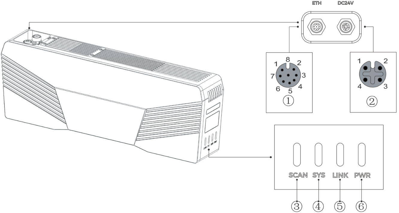
No. |
Name |
Function |
|
|---|---|---|---|
① |
ETH port |
1: MD3_P |
5: MD1_P |
2: MD2_N |
6: MD0_N |
||
3: MD2_P |
7: MD3_N |
||
4: MD0_P |
8: MD1_N |
||
② |
DC 24V port |
1: GND |
3: 24 VDC |
2: GND |
4: 24 VDC |
||
③ |
SCAN indicator light |
Solid green: acquiring and processing data |
|
Not acquiring or processing data |
|||
④ |
SYS indicator light |
Off: camera not started |
|
Solid green: camera starting up |
|||
Blinking green: camera operating properly |
|||
Blinking yellow: abnormal temperature or fan fault |
|||
Blinking red: malfunctioning |
|||
⑤ |
LINK indicator light |
Off: not connected to network |
|
Solid or blinking green: connected to network |
|||
⑥ |
PWR indicator light |
Off: not connected to power |
|
Green: normal voltage |
|||
Solid yellow: voltage lower than 20 V or higher than 28 V |
|||
3. Mount the Camera
The camera can be mounted in the following setups:
| Setup | Requirements |
|---|---|
Mounted to the robot flange and moves with the robot. 
|
|
Mounted to a stationary frame and does not move with the robot. 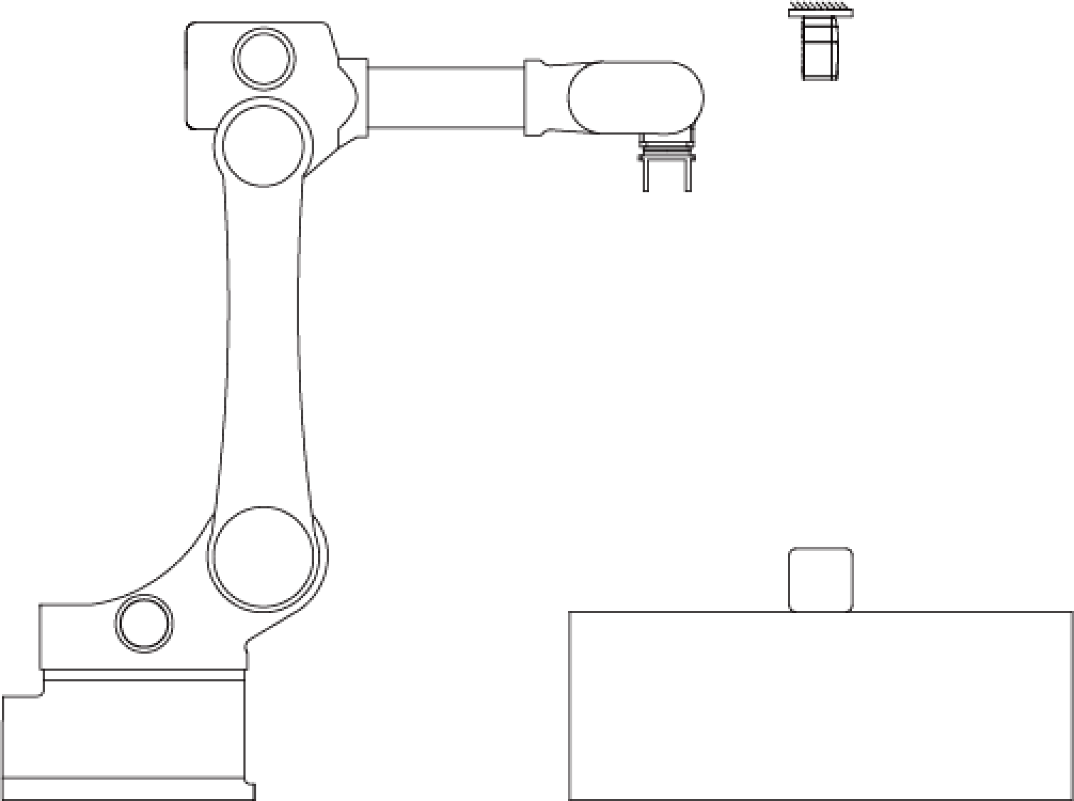
|
|
Mounted to a linear rail and moves with the linear rail. 
|
|
|
After determining the setup, refer to the following sections and secure the camera to the mounting surface through the camera bracket or threaded holes.
|
3.1. Mount through the Camera Bracket
Using the camera bracket, you can mount the camera to the following types of surfaces:
-
T-slot aluminum extrusion
-
Surface with mounting holes opened
|
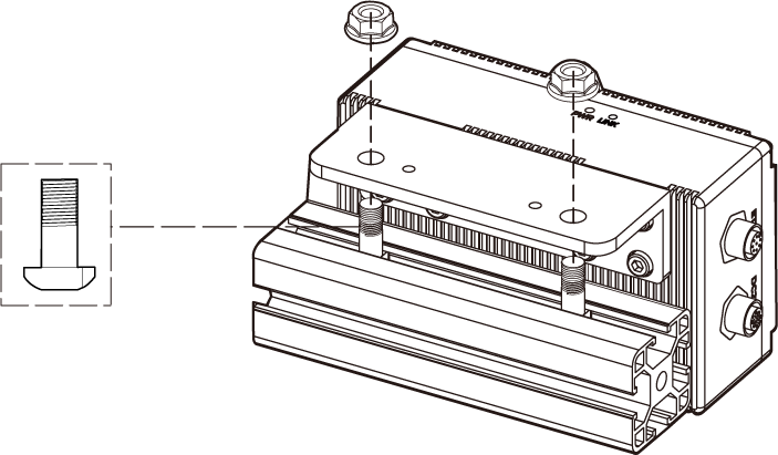
3.1.1. Mount to T-Slot Aluminum Extrusion
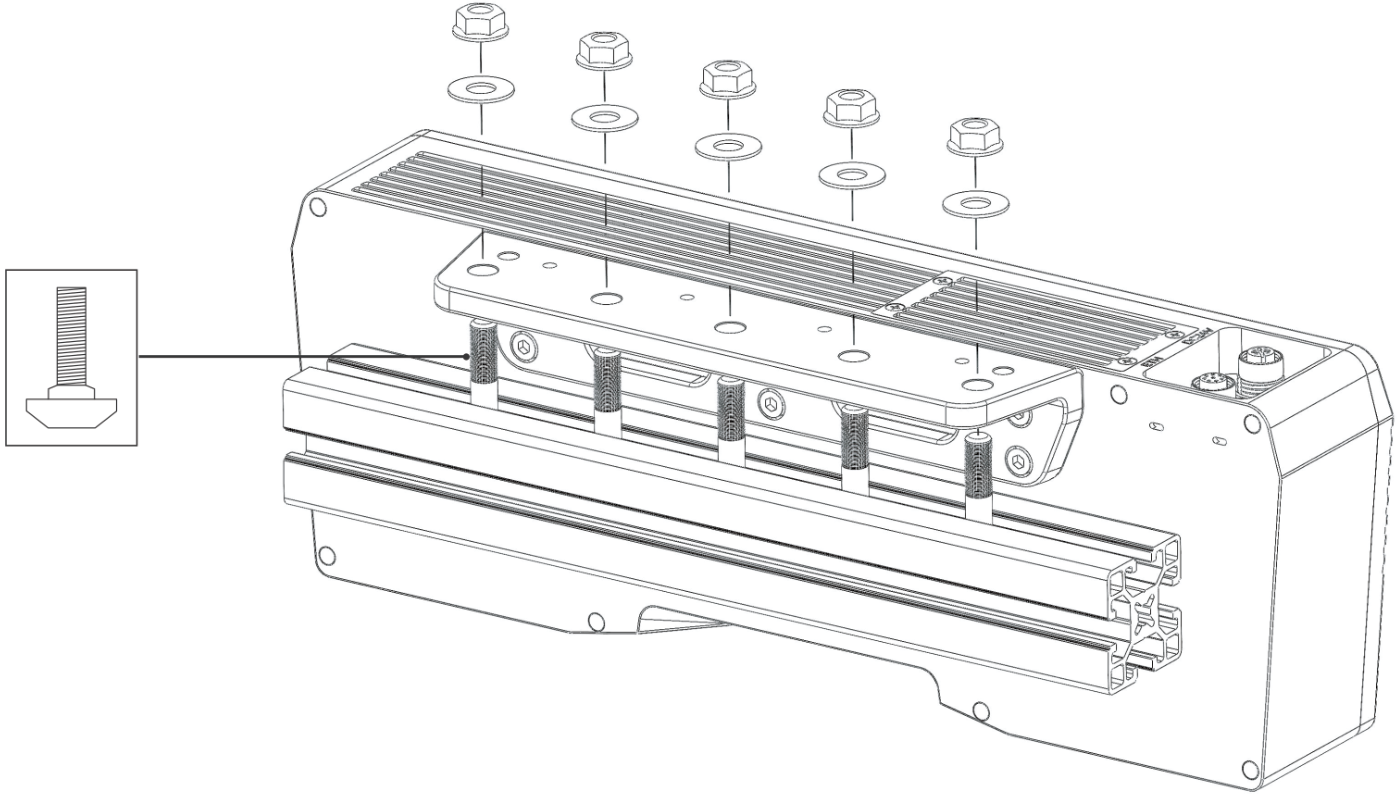
As shown below, place the M8 washers and the M8 × 20 T-bolts, and then use the open-end wrench to tighten the flange nuts. The recommended tightening torque is 12 to 13 N·m.
|
The number of accessories required differs by model. |
-
DEEP-GL, LSR S-GL, LSR L-GL, LSR XL-GL, PRO S-GL, PRO M-GL, and UHP-140-GL:

-
NANO-GL:
-
NANO ULTRA-GL:

-
ULTRA M-GL:
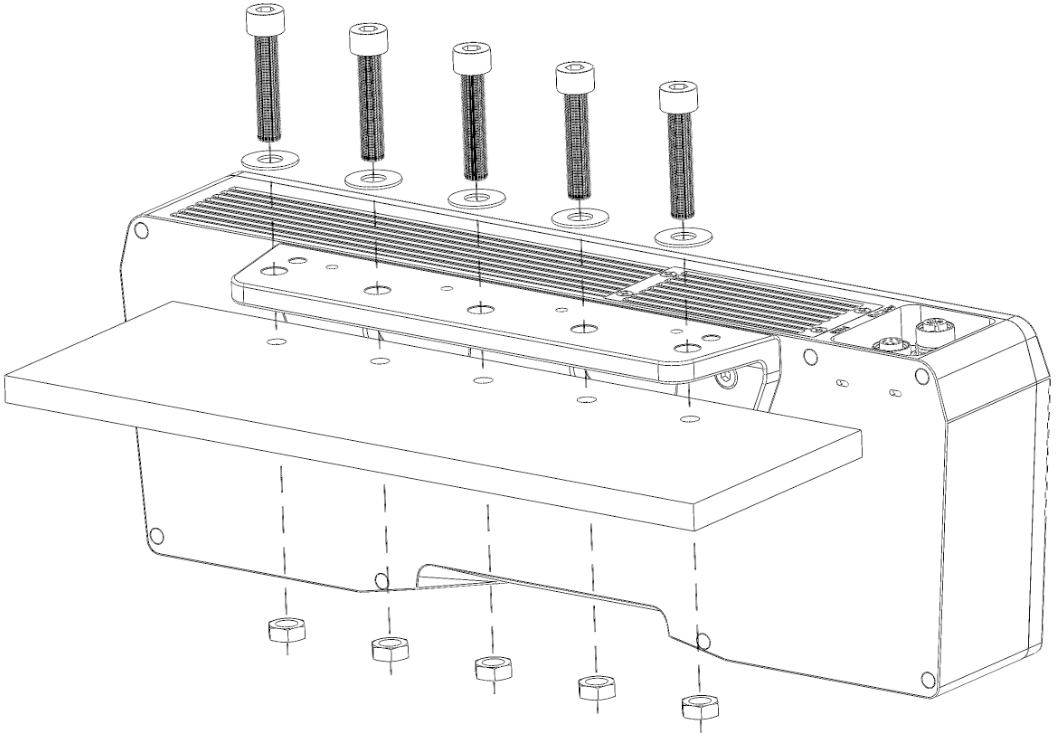
3.1.2. Mount to Surface with Mounting Holes Opened
As shown below, place the M8 washers and the M8 × 20 socket head cap screws, and then use the open-end wrench to tighten the nuts. The recommended tightening torque is 12 to 13 N·m.
|
The number of accessories required differs by model. |
-
DEEP-GL, LSR S-GL, LSR L-GL, LSR XL-GL, PRO S-GL, PRO M-GL, and UHP-140-GL:
-
NANO-GL:

-
NANO ULTRA-GL:

-
ULTRA M-GL:
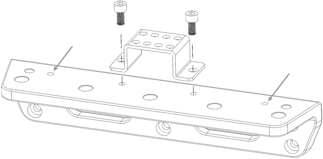
3.1.3. Mount the Cable Tie Mount
After mounting the cable tie mount, you can secure the cables with zip ties to avoid damaging the cables by strain.
As shown below, use the hex key to tighten 2 M5 × 8 socket head cap screws. The recommended tightening torque is 2.2 to 2.5 N·m.
-
DEEP-GL, LSR S-GL, LSR L-GL, LSR XL-GL, PRO S-GL, PRO M-GL, and UHP-140-GL: You can use the threaded holes at different positions (indicated by arrows) to mount the cable tie mount.

-
NANO-GL:

-
NANO ULTRA-GL:

-
ULTRA M-GL: You can use the threaded holes at different positions (indicated by arrows) to mount the cable tie mount.
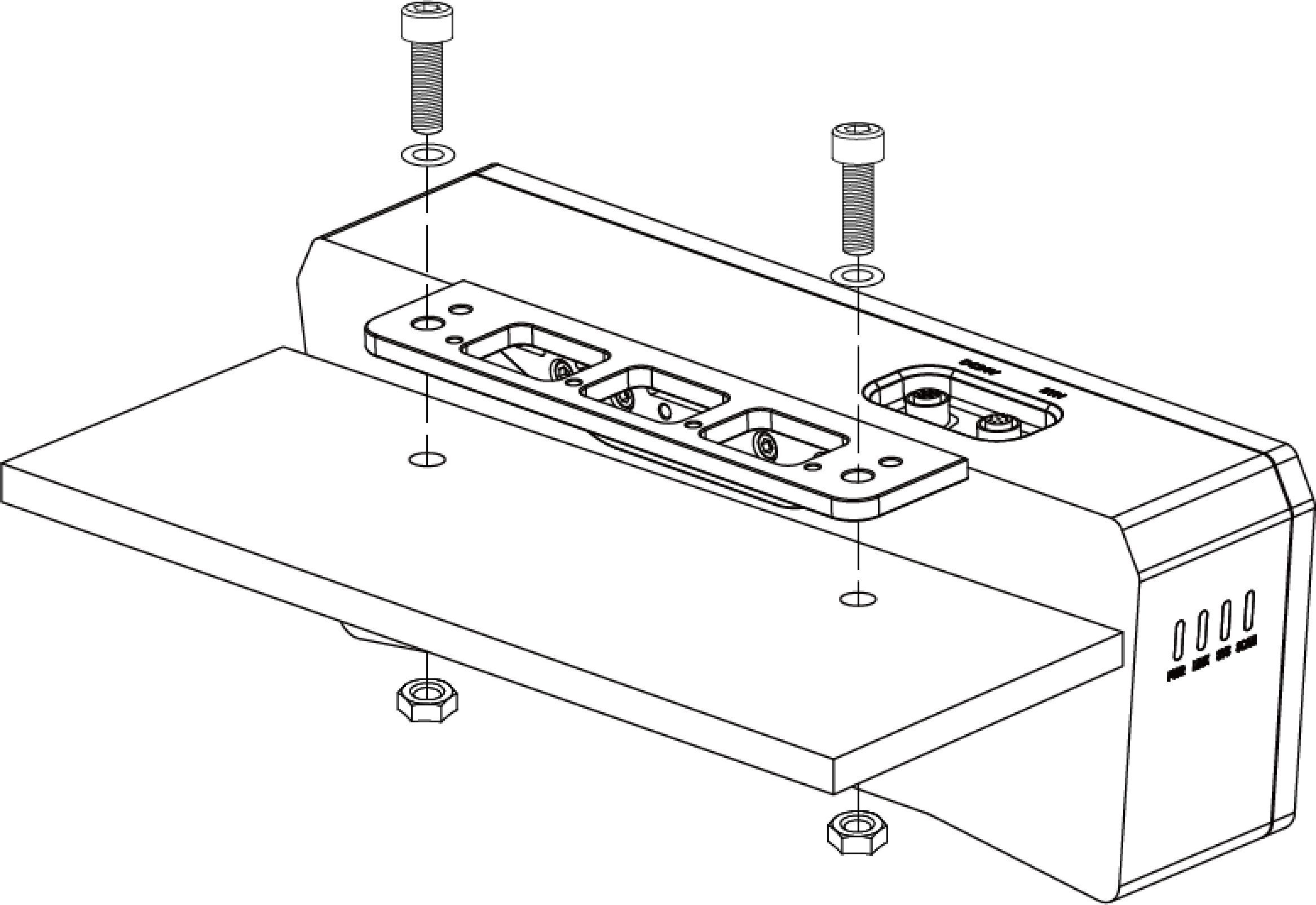
3.2. Mount through Threaded Holes on the Back
|
When mounting LSR S-GL and NANO ULTRA-GL using this method, ensure that the back of the camera is in close contact with a metal surface for heat dissipation, so that the camera does not overheat and malfunction. |
-
Use the hex key to remove the camera bracket. For LSR S-GL and NANO ULTRA-GL, also remove the heat-dissipation panel.
-
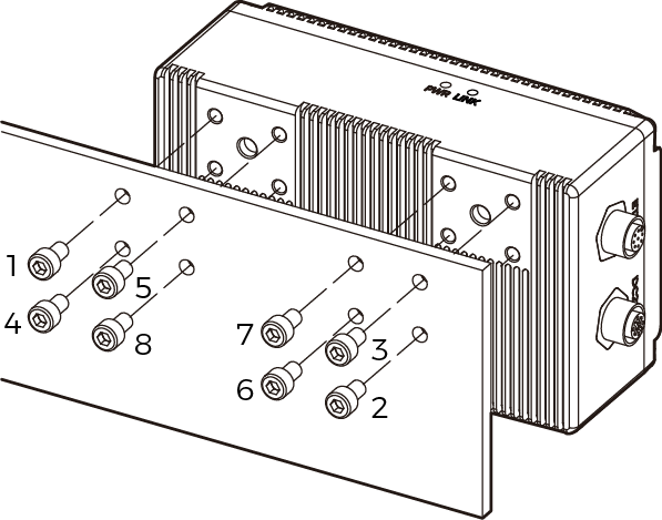
As shown below, place the socket head cap screws of the corresponding specification into the mounting holes. Then, use the hex key to loosely screw on the screws in the specified order, and then fully tighten all the bolts in the specified order.
-
NANO ULTRA-GL: M4 × 8 socket head cap screws (recommended tightening torque: 1.4 to 1.6 N·m)
-
Other models: M5 × 8 socket head cap screws (Recommended tightening torque: 2.2 to 2.5 N·m)
The number of screws required differs by model.
-
-
DEEP-GL, LSR S-GL, LSR L-GL, LSR XL-GL, PRO S-GL, PRO M-GL, and UHP-140-GL:

-
NANO-GL:
-
NANO ULTRA-GL:

-
ULTRA M-GL:
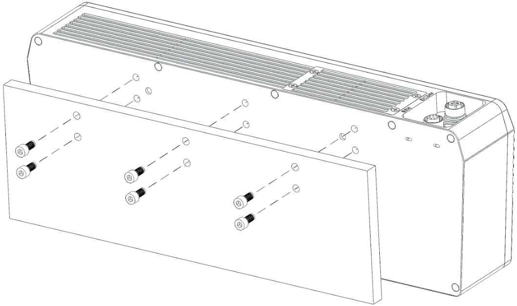
3.3. Mount through Threaded Holes at the Top
The following models provide threaded holes for mounting at the top: LSR S-GL, LSR XL-GL, NANO ULTRA-GL, and UHP-140-GL.
-
Use the hex key to remove the camera bracket.
-
As shown below, place the socket head cap screws of the corresponding specification into the mounting holes. Then, use the hex key to loosely screw on the screws in the specified order, and then fully tighten all the bolts in the specified order.
-
NANO ULTRA-GL: M4 × 8 socket head cap screws (recommended tightening torque: 1.4 to 1.6 N·m)
-
Other models: M5 × 8 socket head cap screws (Recommended tightening torque: 2.2 to 2.5 N·m)
-

4. Connect Cables
Please follow these steps to connect the Ethernet and power cables of the camera.

4.1. Ethernet Cable and DC Power Cable
-
Ethernet cable: Insert the M12-A connector of the Ethernet cable into the ETH port on the camera, and insert the RJ45 connector into the Ethernet port on the IPC.
-
DC power cable: Insert the M12-A connector of the DC power cable into the DC 24V port on the camera.
When inserting the Ethernet cable and DC power cable:
-
Align the bump in the connector with the notch in the port.
-
Tighten the nut. The recommended tightening torque is 0.7 N·m. A gap of about 2 mm remains after the nut is fully tightened.
|
4.2. DIN rail power supply
|

-
Use a flat screwdriver to loosen the screws on the terminals of the DIN rail power supply.
-
Connect the DC power cable: Insert the two wires with the +V labels into the two +V output terminals on the DIN rail power supply, the two wires with the -V labels into the two -V output terminals, and the wire with the PE label into the ground terminal (
 ).
). -
Connect the AC power cable: Insert the live wire into the L input terminal on the DIN rail power supply, the neutral wire into the N input terminal, and the ground wire into the ground terminal (
). -
Use the flat screwdriver to tighten the screws on the terminals.
|
5. Warm Up
To ensure that the accuracy of the data acquired by the product reaches the values listed in the technical specifications, please use the Warm-Up Tool to warm up the product before using it.
-
Recommended warm-up time: 60 minutes for UHP-140-GL and LSR S-GL, and 30 minutes for other models.
-
Recommended data acquisition interval: Warm up the product with the data acquisition interval in actual use. If the data acquisition interval in actual use is not fixed, it is recommended to warm up with the average data acquisition interval. For example, in actual use, data is acquired every 6 to 10 seconds, then during warm-up, data should be acquired every 8 seconds.
The mounting and connection of the camera hardware is completed. The following sections will introduce how to use Mech-Eye Viewer to connect to the camera and control the camera to capture images.
6. Download and Install Mech-Eye SDK
You can download the Mech-Eye SDK installation package from Mech-Mind Download Center.
After decompressing the installation package, double-click the installer to install Mech-Eye SDK. For more information, please refer to Mech-Eye SDK Installation Guide.
7. Set IP Addresses
Before connecting to the camera, please make sure that the following IP address are unique and in the same subnet.
-
Camera IP address
-
The IP address of the IPC Ethernet port connected to the camera
Follow these steps to set the camera IP address:
-
Double-click to open Mech-Eye Viewer.
-
Find the camera to be connected and click
 .
.
8. Connect to Camera
-
Find the camera to be connected in Mech-Eye Viewer, and click Connect.

|
If the software or firmware needs to be upgraded, the Upgrade button is displayed instead. Please click this button to perform upgrade first, and then connect to the camera. |
9. Capture Images
Click ![]() to perform image capturing once.
to perform image capturing once.
|
Clicking |
Click the data types below the image capturing buttons to check the 2D image, depth map and point cloud obtained from the camera.
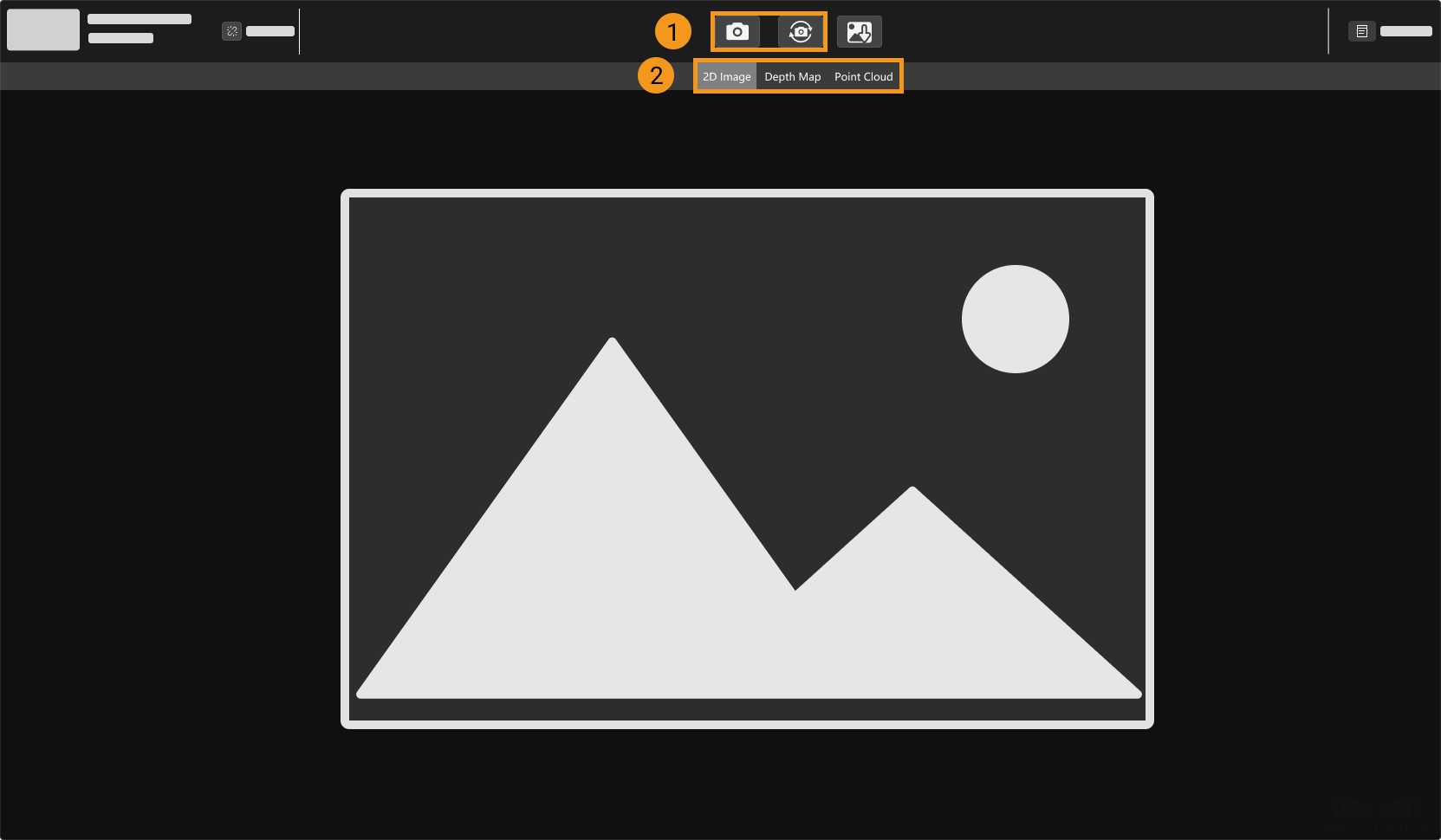
| For more information on image capturing and data types, please refer to Acquire and View Data. |
10. Adjust Parameters
If the quality of the obtained 2D image, depth map and point cloud is not satisfactory, you can adjust the relevant parameters in the Parameters tab on the right of the software to improve data quality.
10.1. Determine Data Quality
Based on the following criteria, roughly determine the quality of the obtained data.
-
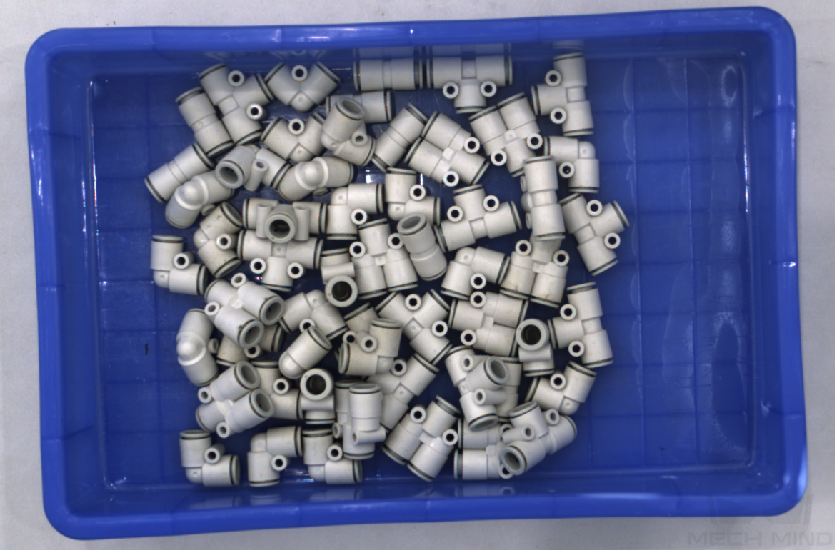
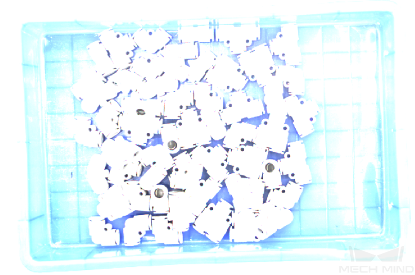
2D image: the 2D image is not too bright or too dark; the surface features of the target object are clearly visible.
Too dark Good Too bright 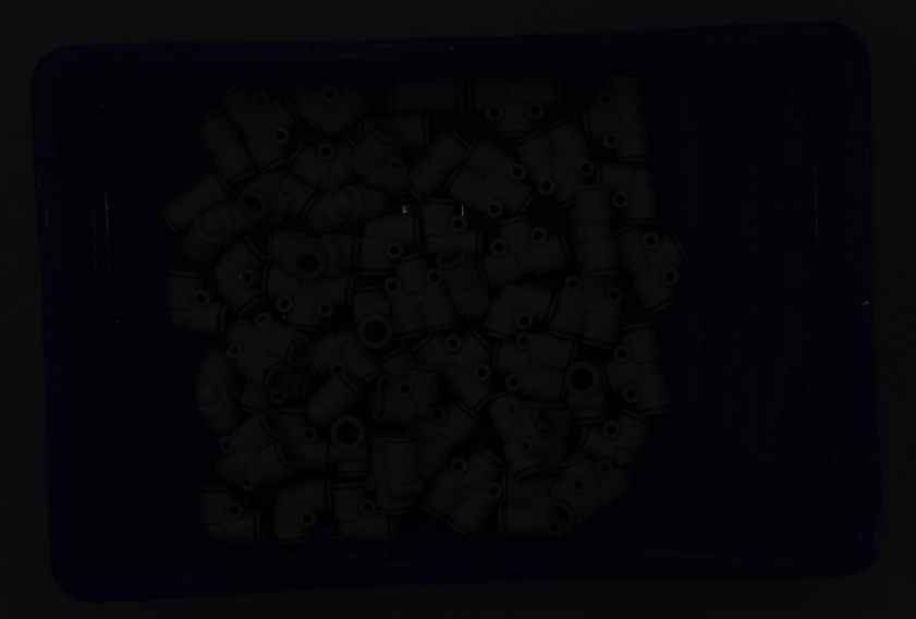
-
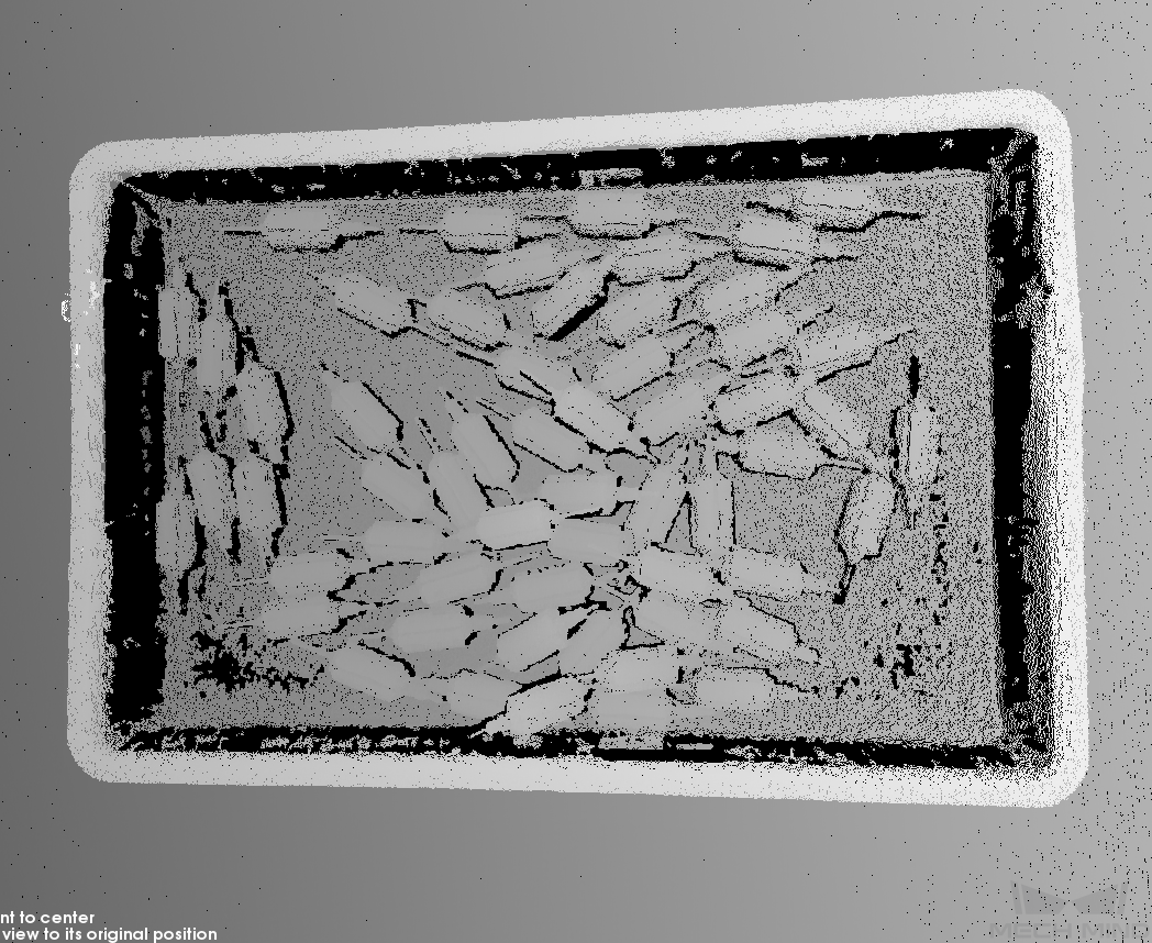
Depth map and point cloud: in the depth map and point cloud, the data corresponding to the target object should be complete. In the following example, the target object is the rotors.
Point cloud of target object incomplete Point cloud of target object complete 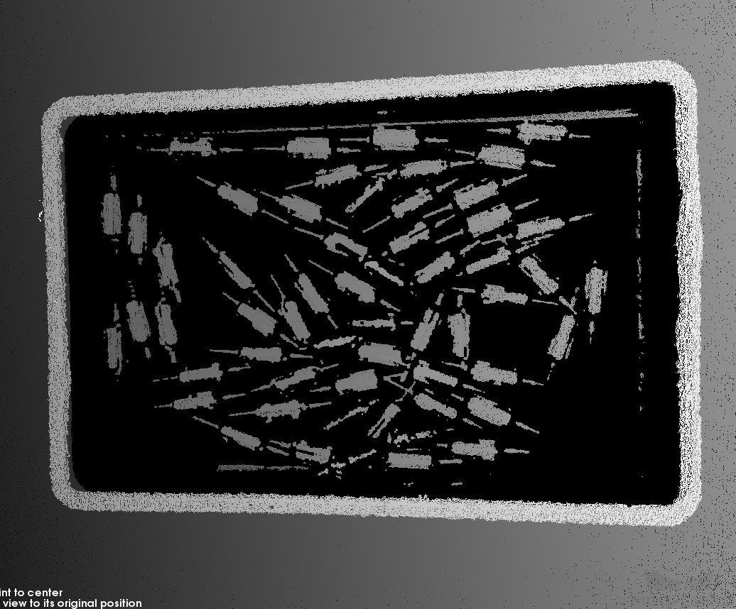
10.2. Improve 2D Image Quality
-
Set the Exposure Mode parameter in the 2D Parameters category to Timed, and then adjust the Exposure Time parameter.
-
If the 2D image is too dark, increase Exposure Time.
-
If the 2D image is too bright, decrease Exposure Time.
DEEP-GL and LSR series provide two types of 2D images corresponding to different parameters. For detailed information, please refer to Parameters of DEEP-GL Series and Parameters of LSR Series.
-
-
Capture images again and check the quality of the 2D image.
10.3. Improve Quality of Depth Map and Point Cloud
-
Adjust the Exposure Time parameter in the 3D Parameters category.
-
If the object is dark-colored or not reflective, increase Exposure Time.
-
If the object is light-colored or reflective, decrease Exposure Time.
-
-
Capture images again and check the quality of the depth map and point cloud.
| For more explanations of the parameters, please refer to Parameter Reference Guide. |
11. Use Data
The 2D image, depth map and point cloud obtained through Mech-Eye Viewer can be saved locally or can be output to Mech-Vision or third-party machine vision software for subsequent processing and calculation.
-
Save the data: Click
 in the data acquisition area, set the destination path, check the data types to be saved, and then click Save.
 -
Use the data in Mech-Vision: Please refer to Vision System Tutorial and learn how to build the entire vision system that includes Mech-Vision.
-
Use the data in third-party machine vision software: The data obtained by the camera can be transmitted to third-party software through Mech-Eye API or the GenICam interface.