Intrinsic Parameter Tool
This tool is used to check if the camera intrinsic parameters are accurate and to correct the intrinsic parameters. The coordinates of points are accurate only if the intrinsic parameters are accurate.
Click Tools in the menu bar and select Intrinsic Parameter Tool to open the Intrinsic Parameter Tool window. You can then perform the intrinsic parameter check and correction operations.
Check Intrinsic Parameters
| Before checking the intrinsic parameters, use the Warm-Up Tool to warm up the device. Then, refer to Calibration Board Selection and select the proper calibration board according to the camera model and the actual working distance. |
Process
To use Intrinsic Parameter Tool to check the camera intrinsic parameters, follow these steps.
-
In 1. Place calibration board and check image quality, check whether the 2D image and depth map satisfy the image requirements.
-
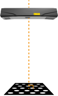
Place the calibration board within the camera’s FOV and ensure that it is within the recommended working distance of the camera and perpendicular to the camera’s central axis:
-
Click the Acquire images button to acquire the 2D image and depth map of the calibration board. Make sure that the obtained 2D image and depth map satisfy the following requirements:
-
The circles on the calibration board are completely captured.
-
The overall calibration board in the 2D image should have balanced brightness, not too dark, too bright, or uneven. The calibration circles should be clear.
-
The calibration circles in the depth map should be intact.
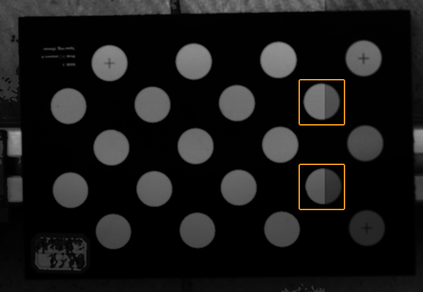
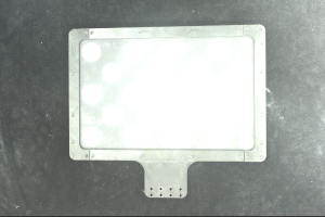
Examples of 2D images of the calibration board:
Image too dark, the circles on the calibration board cannot be easily discerned. Image brightness uneven, the circles on the calibration board cannot be easily discerned. Circles on the calibration board are complete, and circle boundaries are clearly visible. Image too bright, the circles on the calibration board cannot be easily discerned. 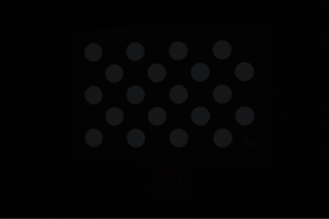
If the acquired 2D image does not satisfy the image requirements, refer to Adjust 2D And 3D Exposure Parameters During Calibration to adjust the parameters.
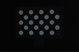
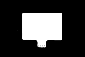
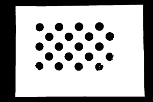
Examples of depth maps of the calibration board:
Exposure time too short, the circles on the calibration board are incomplete. Circles on the calibration board / the entire calibration board are complete. Exposure time too long, some or all the circles on the calibration board are lost. 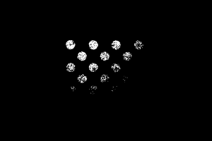

If the acquired depth map does not satisfy the image requirements, refer to Adjust 2D And 3D Exposure Parameters During Calibration to adjust the 3D parameters.
For more information about parameter adjustment, see Parameter Reference Guide.
-
-
-
In 2. Select model of placed calibration board, set the specifications of the calibration board:
-
For standard calibration board, select Standard for Calibration board category, and choose the calibration board model according to the label on the calibration board.
-
For customized calibration board, select Customized for Calibration board category, choose the appropriate Calibration board type as shown in the illustration, and set the Rows, Columns, and Spacing.
-
-
In 3. Check and process intrinsic parameters, click Check intrinsic parameters to start checking the camera intrinsic parameters. When the check is completed, a window of the check results will pop up.
-
If an error message is displayed, please troubleshoot the issue according to the next section.
Troubleshoot Common Issues
The following issues may be encountered while checking the intrinsic parameters.
Large Result from the Intrinsic Parameter Check
Symptom:
The intrinsic parameter check results are displayed in red, indicating that the camera intrinsic parameter check results are large.
Solutions:
Try the following solutions:
-
Check if the calibration board model or category is correct.
-
If incorrect, select the correct model or category. Then, click the Check intrinsic parameters button to check the camera intrinsic parameters again.
-
If correct, proceed to the next step.
-
-
Check if the 2D image and depth map satisfies the image requirements. Please refer to the image requirements.
-
If the 2D image does not satisfy the requirements, refer to Adjust 2D And 3D Exposure Parameters During Calibration to adjust the parameters. If the depth map does not satisfy the requirements, refer to Adjust 2D And 3D Exposure Parameters During Calibration to adjust the 3D parameters. Then, click the Check intrinsic parameters button to check the camera intrinsic parameters again.
-
If the images satisfy the requirements, proceed to the next step.
-
-
Check if the camera has malfunctioned or sustained damage due to collisions with other devices, and contact Technical Support.
Circles on the Calibration Board not Detected
Symptom:
The intrinsic parameter check result window displays this message: Circles on the calibration board not detected.
Solutions:
Try the following solutions:
-
Check if the calibration board model or category is correct.
-
If incorrect, select the correct model or category. Then, click the Check intrinsic parameters button to check the camera intrinsic parameters again.
-
If correct, proceed to the next step.
-
-
Check if the 2D image and depth map satisfies the image requirements. Please refer to the image requirements.
-
If the 2D image does not satisfy the requirements, refer to Adjust 2D And 3D Exposure Parameters During Calibration to adjust the parameters. Then, click the Check intrinsic parameters button to check the camera intrinsic parameters again.
-
If the images satisfy the requirements, proceed to the next step.
-
-
Adjust the detection parameters, such as drawing aid circles or adjusting the feature detection parameters (advanced). Then, click the Check intrinsic parameters button to check the camera intrinsic parameters again.
-
If the check succeeded, the troubleshooting has been completed.
-
If the intrinsic parameter check result window still displays Circles on the calibration board not detected, please contact Technical Support.
-
Draw Aid Circle
This function can assist you in resolving the issue of circles on the calibration board not detected.
Follow these steps to use the Draw aid circle function:
-
In 3. Check and process intrinsic parameters, click the Draw aid circle button.
-
Find a complete circle on the calibration board in the 2D image.
-
Press Ctrl and click the left mouse button to select the circle center.
-
Move the cursor to any point on the circumference, press the Ctrl key, and click the left mouse button to set the circle radius and complete the drawing.
-
-
In 3. Check and process intrinsic parameters, click Check intrinsic parameters to check the camera intrinsic parameters again.
|
Adjust Feature Detection Parameters (Advanced)
This function can assist you in resolving the issue of circles on the calibration board not detected.
Follow these steps to use the Adjust Feature Detection Parameters (Advanced) function:
-
In 3. Check and process intrinsic parameters, click Adjust feature detection parameters (advanced).
-
Adjust the displayed feature detection parameters according to the actual situation.
-
If not all the circles on the calibration board can be captured, check Allow absence of some circles, and adjust the newly displayed feature detection parameters.
-
In 3. Check and process intrinsic parameters, click Check intrinsic parameters to check the camera intrinsic parameters again.
Valid Feature Points Not Found in Depth Map
Symptom:
The intrinsic parameter check result window displays this message: Valid feature points not found in depth map.
Solutions:
Check if the depth map satisfies the requirements. Please refer to the image requirements.
-
If the acquired depth map does not satisfy the image requirements, refer to Adjust 2D And 3D Exposure Parameters During Calibration to adjust the 3D parameters. Then, click the Check intrinsic parameters button to check the camera intrinsic parameters again.
-
If the depth map satisfies the requirements, please contact Technical Support.
Improper Exposure of the 2D Image
Symptom:
The message box in the lower part of the software interface displays that the brightness in the 2D image is too bright, too dark. or uneven, which does not meet the image requirements.
| For more accurate check results, it is recommended to adjust the parameters based on the following solutions. |
Solutions:
Try the following solutions:
-
If the 2D image is too bright or too dark, refer to Adjust 2D And 3D Exposure Parameters During Calibration to adjust the parameters and ensure the quality of the 2D image.
-
If the brightness in the 2D image is uneven, refer to Uneven Brightness in the 2D Image and check and adjust the related settings to achieve uniform brightness in each circle on the calibration board.
Circles on the Calibration Board Too Small
Symptom:
The message box in the lower part of the software interface displays that The circles on the calibration board occupy too little of the camera’s field of view.
| For more accurate check results, it is recommended to adjust the parameters based on the following solutions. |
Solutions:
-
If the current resolution is too low, it is recommended to increase the image resolution referring to Change Image Resolution.
-
If the current calibration board is too small, it is recommended to use a larger calibration board.
Correct Intrinsic Parameters
This function can assist you in resolving the issue of large errors in the intrinsic parameters. It is recommended to use the intrinsic parameter correction feature in the following scenarios:
-
The scalar difference value in the intrinsic parameter check results exceeds the values in the table below.
-
The project has high precision requirements for the camera, and the current camera precision does not meet the actual needs.
| Model | Scalar difference value |
|---|---|
DEEP-GL |
0.6% |
LSR L-GL, LSR S-GL, Laser L Enhanced |
0.5% |
LSR XL-GL |
0.4% |
PRO M-GL, PRO S-GL, NANO-GL, NANO ULTRA-GL |
0.3% |
|
If no abnormalities are found during the intrinsic parameter check, you can click the Start correcting intrinsic parameters button to correct intrinsic parameters on the Correct Intrinsic Parameters page.
Place Calibration Board
When using the Correct Intrinsic Parameters function, place the calibration board according to the following requirements:
-
Ensure that the plane of the calibration board is as perpendicular as possible to the camera’s central axis:
-
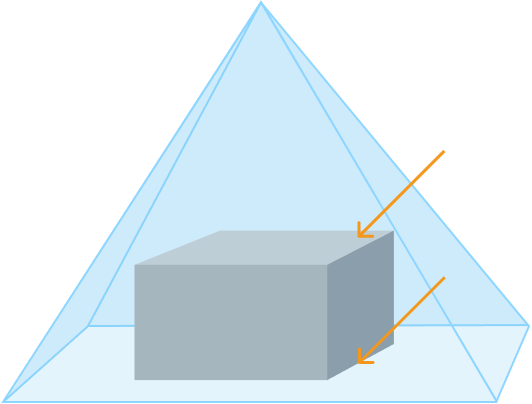
Place the calibration board on the following two planes: the top surface of the target object (Plane 1) and the bottom surface (Plane 2). Ensure that the distance between the two planes is at least 100 mm.
For example, for bin-picking or (de)palletizing applications, the calibration board should be placed at the top and bottom of the bin or palletized load.
-
Ensure that the calibration board remains within the camera’s field of view.
This tool provides assistance to ensure that the calibration board remains within the camera’s field of view. Follow these steps to use the tool:
-
Click the Start acquisition images button and move the calibration board to different positions on the current plane, and the 2D image and depth map of the calibration board will refresh at a fixed frequency (approximately once every 5 seconds).
-
If both the 2D image and depth map are complete, it indicates that the position is within the camera’s field of view. If either the 2D image or depth map is missing, it indicates that the position may be outside the camera’s field of view.
-
After confirming the camera’s field of view on the current plane, click the Stop acquisition images button. Then, refer to the next section and add the data from the current plane.
-
After adding the data from the current plane, refer to this process and continue adding data from the other plane.
-
The start/stop acquisition images button and other buttons on this page cannot be used at the same time.
-
Acquire and Validate Data
The calibration board must be moved on two planes (Plane 1 and Plane 2) and click the Acquire data button to acquire data of the calibration board in different positions. The data validated is considered valid. The validation standards are as follows:
| Validation item | Validation value |
|---|---|
Minimum area coverage |
25% |
Minimum length coverage |
50% |
Minimum width coverage |
50% |
Minimum data sets |
3 |
When acquiring data on two planes, the following requirements must be met:
-
First acquire the data from Plane 1, and then acquire the data from Plane 2.
-
When there is data from Plane 2, the data from Plane 1 cannot be modified.
-
After the data from both planes has been acquired and validated, click the Correct Intrinsic Parameters button to start the intrinsic parameter correction.
| You can use the Areas covered by acquired data below to assist in adjusting the position of the calibration board, ensuring that the acquired data passes validation. |
After the acquired data from both Plane 1 and Plane 2 pass validation, you can click the Correct Intrinsic Parameters button to start the intrinsic parameter correction. If an error message is displayed during data acquisition and adding, refer to the next section for troubleshooting.
If the intrinsic parameter correction is successful, click the Update intrinsic parameters button in the Correct Intrinsic Parameters Result popup window to apply the corrected intrinsic parameters and improve the camera accuracy.
If the intrinsic parameter correction fails, refer to the instructions in the popup window for troubleshooting.
Troubleshoot Common Issues
The following issues may be encountered while correcting the intrinsic parameters.
Circles on the Calibration Board not Recognized
Symptom:
The message box in the lower part of the software interface displays Failed to recognize the circles on the calibration board in the 2D image.
Solutions:
Try the following solutions:
-
Check if the calibration board is within the view of all cameras.
-
If not, adjust its position. Then, click Acquire data again.
-
If the calibration board is within the view of all cameras, proceed to the next step.
-
-
Check if the 2D image satisfies the image requirements. Please refer to the image requirements.
-
If the 2D image is too bright or too dark, refer to Adjust 2D And 3D Exposure Parameters During Calibration to adjust the parameters and ensure the quality of the 2D image. Then, click Acquire data again.
-
If the brightness in the 2D image is uneven, refer to Uneven Brightness in the 2D Image and check and adjust the related settings to achieve uniform brightness in each circle on the calibration board. Then, click Acquire data again.
-
If the 2D image satisfies the requirements, proceed to the next step.
-
-
If the issue persists, save the technical file and contact Technical Support.
Not All Circles on the Calibration Board Recognized
Symptom:
The message box in the lower part of the software interface displays It is required to recognize N circles on the calibration board but only M circles are recognized.
Solutions:
-
Check if the calibration board is within the camera’s field of view and the projector’s projection range.
-
If not, adjust the position of the calibration board to ensure it is within the camera’s field of view and the projector’s projection range, and adjust the 3D parameters to ensure proper exposure. Then, click Acquire data again.
-
If yes, proceed to the next step.
-
-
If the issue persists, save the technical file and contact Technical Support.
Acquired Data Not on the Current Plane
Symptom:
The message box in the lower part of the software interface displays The acquired data is not on the current plane. It indicates that the distance between the current data plane and the camera is not within the acceptable distance between the plane and the camera.
Solutions:
-
Adjust the calibration board’s position so that its distance from the camera falls within the acceptable range. Then, click Acquire data again.
-
If the issue persists, save the technical file and contact Technical Support.
Error in Current data Too Large
Symptom:
The message box in the lower part of the software interface displays The error in current data is too large.
Solutions:
Try the following solutions:
-
Check if there are more than one calibration board within the camera’s field of view.
-
If yes, remove the calibration boards other than the target calibration board. Then, click Acquire data again.
-
If there is only the target calibration board, proceed to the next step.
-
-
Check if the 2D image satisfies the image requirements. Please refer to the image requirements.
-
If the 2D image is too bright or too dark, refer to Adjust 2D And 3D Exposure Parameters During Calibration to adjust the parameters and ensure the quality of the 2D image. Then, click Acquire data again.
-
If the brightness in the 2D image is uneven, refer to Uneven Brightness in the 2D Image and check and adjust the related settings to achieve uniform brightness in each circle on the calibration board. Then, click Acquire data again.
-
If the 2D image satisfies the requirements, proceed to the next step.
-
-
Check if the calibration board is within the camera’s field of view and the projector’s projection range.
-
If not, adjust the position of the calibration board to ensure it is within the camera’s field of view and the projector’s projection range, and adjust the 3D parameters to ensure proper exposure. Then, click Acquire data again.
-
If yes, proceed to the next step.
-
-
If the issue persists, save the technical file and contact Technical Support.
Failed to Acquire Data
Symptom:
The message box in the lower part of the software interface displays Failed to acquire data.
Solutions:
-
Save the technical file.
-
Check the camera connection.
-
If the camera connection is abnormal, connect the camera again. Then, click Acquire data again.
-
If the camera is connected, please contact Technical Support.
-