Hand-Eye Calibration
This topic introduces how to perform hand-eye calibration with the hand_eye_calibration samples on Windows.
| Please refer to Usage Guide for HALCON Samples to obtain the samples and check the prerequisites for using the samples. |
The hand_eye_calibration folder contains the following two samples:
-
determine_calibration_poses: used to determine the calibration poses used during the hand-eye calibration.
-
perform_hand_eye_calibration: used to perform hand-eye calibration.
|
Preparation
Before using the HALCON samples to perform hand-eye calibration, complete the following steps:
-
The accuracy of the robot is good enough, and the robot can operate properly.
-
Prepare the calibration board that came with the camera, and mount the calibration board.
-
Make sure that the quality of the 2D image and depth map meet the requirements.
-
Make sure that the camera intrinsic parameters are accurate.
Edit the Samples
After determining the calibration poses with the determine_calibration_poses sample, you will use the perform_hand_eye_calibration sample to perform hand-eye calibration.
The following information must be identical in the two samples:
-
The camera to be connected
-
Calibration board model
Besides, the Euler angle convention in the robot_pose JSON file should be set before determining the calibration poses.
Select the Camera
Before running the samples, you need to set the camera to be connected in the sample to make sure the two samples connect to the same camera. Follow these steps:
-
Open the sample in HDevelop: Open HDevelop, and drag the sample into HDevelop.
-
Step over the program (click the
 button in the toolbar repeatedly), until the Variable Inspect: MechEyeCamers window pops up.
 -
This window displays all the available cameras. Double-click the camera that you want to connect, and copy the name after unique_name: or user_name:.

user_name is the custom camera name. You can customize the camera name in Mech-Eye Viewer. -
Locate the following line, and replace MechEye with the copied unique_name or user_name.
DeviceInfo := 'MechEye'
Set Calibration Board Model
Follow these steps to set the calibration board model:
-
Open the sample in HDevelop: Open HDevelop, and drag the sample into HDevelop.
-
Set the calibration board model: The default model is BDB-5. If you are using another model, locate the following operator, and change BDB-5 to the calibration board model in use.
set_framegrabber_param (AcqHandle, 'BoardType', 'BDB-5')
Set Euler Angle Convention and Unit
The calibration poses determined using the determine_calibration_poses sample need to be entered into the robot_pose JSON file. The default Euler angle convention in this file is sxyz, and the default unit is degree. Follow these steps to set the Euler angle convention:
-
Open the robot_pose JSON file.
-
Set the Euler angle convention: locate the following line, and replace sxyz with the Euler angle convention of the robot in use. For the Euler angle conventions already supported in the sample, please refer to Supported Euler Angle Conventions.
"EulerType":"sxyz" -
Set the Euler angle unit: if you need to enter Euler angles in radians, locate the following line, and replace true with false.
"FromDegree":true -
Save the robot_pose JSON file.
Determine Calibration Poses
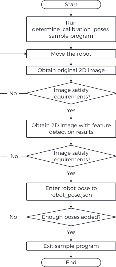
Instructions
Before performing hand-eye calibration, you need to determine at least 15 calibration poses. Follow these steps to determine the calibration poses:
-
Run the sample by clicking
 in the toolbar or pressing the F5 key. When the sample runs to the line read_char (WindowHandle, Char, ReCode), the sample will pause and wait for command input in the following steps.
If the camera cannot be connected, please check if it is already connected by Mech-Eye Viewer or another GenICam client. -
Move the robot to a candidate calibration pose with the teach pendant.
Calibration poses need to satisfy certain requirements. The HALCON Reference provides some guidance: click in HDevelop and check the Calibration chapter. -
Press P to obtain the 2D image from the camera.
-
If the calibration board is not entirely captured, please move the robot and obtain the 2D image again.
-
If the entire calibration board is captured, proceed to the next step.
-
-
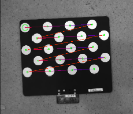
Press T to obtain the 2D image containing the feature detection results.
-
If the camera did not detect the circles on the calibration board, no image will be displayed in HDevelop. In this case, please move the robot and obtain the original 2D image and the 2D image containing the feature detection results again.
-
If the camera can detect the circles on the calibration board, a 2D image containing the feature detection results (as shown below) will be displayed in HDevelop. Please proceed to the next step.
-
-
Check the robot teach pendant, and enter the current robot pose to the robot_pose JSON file. The translational component of the pose should be in mm, and the unit of the rotational component (Euler angles) should match the setting in the robot_pose JSON file.
It is recommended to save the pose on the teach pendant. When performing hand-eye calibration, you can use the saved poses to move the robot. -
Repeat steps 2 to 5 to determine more calibration poses.
-
After determining at least 15 calibration poses, press Q to exit the sample.
-
Set the number of calibration poses in the robot_pose JSON file: Open the robot_pose JSON file, and locate the following line. Replace 15 with the actual number of calibration poses determined.
"pose_count":15
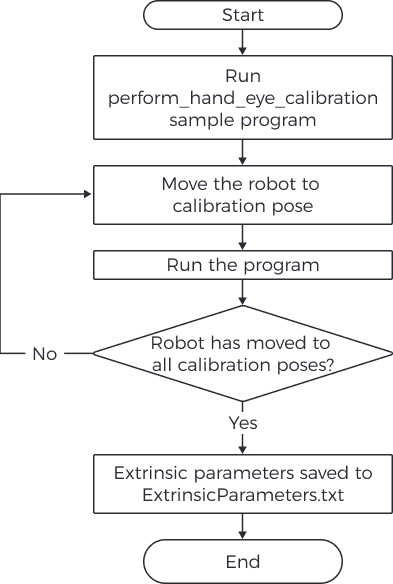
Perform hand-eye calibration
After determining the robot calibration poses, you can perform hand-eye calibration by running the perform_hand_eye_calibration sample.
Set Camera Mounting Method
Before performing hand-eye calibration, please set the camera mounting method in the sample.
The default mounting method is Eye in Hand. If your camera is mounted in the Eye to Hand mode, please locate the following operator, and replace EyeInHand with EyeToHand.
set_framegrabber_param (AcqHandle, 'CalibrationType', 'EyeInHand')Switch Reference Frame
The sample contains an operator that can switch the reference frame in which the point cloud is output from the camera.
The default setting is not to switch the reference frame. If you would like to switch to the robot reference frame, please locate the following operator in the captureTranformedPointCloud procedure, and replace false with true.
set_framegrabber_param (AcqHandle,'Scan3dCoordinateTransformEnable',false)Instructions
Follow these steps to perform hand-eye calibration:
-
Run the sample by clicking
in the toolbar or pressing the F5 key. The sample will stop when it runs to the stop operator. -
Move the robot to the calibration pose in the robot_pose JSON file.
Please move the robot to the calibration poses in the exact order as they are written in the JSON file. Otherwise, the subsequent calculation of the extrinsic parameters will fail. -
Run the sample by clicking
in the toolbar or pressing the F5 key. The camera will acquire data. -
In the Control Variables area, check the value of CollectResult.
-
If SUCCESS is displayed, please proceed to the next step.
-
If an error is displayed, please troubleshoot according to the displayed error code, and then determine the calibration poses again.
-
-
A message saying Move the robot to the next calibration pose will be displayed on the image. Please repeat steps 2 to 3.
After the robot has moved to all the calibration poses in the robot_pose JSON file, when you run the sample again, the extrinsic parameters will be calculated. -
In the Control Variables area, check the value of CalibResult.
-
If SUCCESS is displayed, then hand-eye calibration has succeeded. In the folder where the sample is stored, you can find the ExtrinsicParameters TXT file that contains the extrinsic parameters and the obtained point cloud.
-
If an error is displayed, please troubleshoot according to the displayed error code, and then determine the calibration poses again.
-
Supported Euler Angle Conventions
The conversion from the following Euler angle conventions to quaternions is already supported in the sample.
| Common representation | Euler angle convention | Robot brand |
|---|---|---|
Z-Y'-Z"/OAT |
rzyz |
Kawasaki |
Z-Y'-X"/yaw, pitch, roll |
rzyx |
ABB |
KUKA |
||
X-Y-Z/WPR |
sxyz |
FANUC |
YASKAWA |
||
ROKAE |
||
UR |
||
X-Y'-Z" |
rxyz |
/ |
Z-X'-Z" |
rzxz |
/ |
|
Hand-Eye Calibration Parameters
This section introduces the parameters used during hand-eye calibration.
BoardType
This parameter is used to set the model of the calibration board in use.
Value list and descriptions:
| Value | Description |
|---|---|
BDB-5 |
The recommended distance from the calibration board to the camera is < 0.6 m |
BDB-6 |
The recommended distance from the calibration board to the camera is 0.6–1.5 m |
BDB-7 |
The recommended distance from the calibration board to the camera is > 1.5 m |
OCB-005 |
Only used for Eye-to-Hand projects with high accuracy requirements |
OCB-010 |
|
OCB-015 |
|
OCB-020 |
|
CGB-020 |
The recommended distance from the calibration board to the camera is < 0.6 m |
CGB-035 |
The recommended distance from the calibration board to the camera is 0.6–1.5 m |
CGB-050 |
The recommended distance from the calibration board to the camera is > 1.5 m |
ExtrinErrCode
This read-only parameter is used to check the status codes returned during the hand-eye calibration process.
| Status code | Description |
|---|---|
SUCCESS |
Successfully executed. |
POSE_INVALID |
The pose format is incorrect. Please input quaternions. |
IMAGE2D_EMPTY |
The 2D image is invalid. |
FIND_CORNERS_FAIL |
Feature detection of the 2D image failed. Please adjust the parameters for the 2D image. |
DEPTH_EMPTY |
The depth map is invalid. |
CORNERS_3D_INVALID |
Feature detection of the depth map failed. Please adjust the parameters for the depth map. |
POSES_INSUFFICIENT |
Not enough poses are input. Please input at least 15 calibration poses. |