Use Image Acquisition Assistant to Control Camera
Using the image acquisition assistant provided by HDevelop, you can quickly connect to the camera, acquire data, and adjust camera parameters.
To open the image acquisition assistant: open HDevelop, and in the menu bar, select .
Connect to the Camera
-
In the Image Acquisition window, under the Source tab, select Image Acquisition Interface, and select GigEVision2 from the drop-down menu.
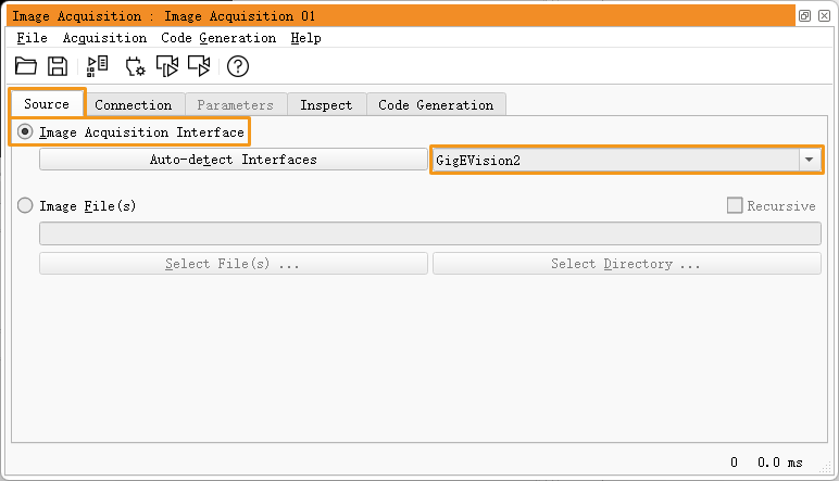
If the GigEVision2 option is unavailable, the GigEVision2 image acquisition interface is not installed. Please refer to HALCON’s Installation Guide and install the interface through MVTec Software Manager (SOM). -
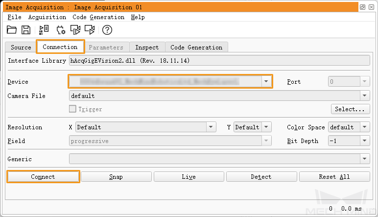
Under the Connection tab, from the drop-down menu of Device, select the device you would like to connect. Then, click Connect in the lower left.
|
Acquire Data
To acquire data once: under the Connection tab, click Snap.
|
If the data acquisition process takes too long, you can increase the MTU size of the camera, and enable jumbo frames on your computer. |
You can also acquire data multiple times or continuously. To do this, you need to adjust the AcquisitionMode parameter first.
-
To acquire data multiple times:
-
Switch to the Parameters tab, set the value of the AcquisitionMode parameter to MultiFrame.
-
Click Refresh in the upper right, and then set the number of times for data acquisition in the AcquisitionFrameCount parameter.
-
Switch to the Connection tab and click Live to acquire data.
-
After the set times of data acquisition are completed, the Live button becomes Stop. Click Stop to stop data acquisition.
-
-
To acquire data continuously:
-
Switch to the Parameters tab, set the value of the AcquisitionMode parameter to Continuous.
-
Switch to the Connection tab and click Live to acquire data.
-
The Live button becomes Stop. Click Stop to stop data acquisition.
-
|
Select Data Type
After the camera is connected, the 2D image is obtained by default. You can select whether to obtain 2D image or depth map by adjusting the DeviceScanType parameter.
-
Click the Parameters tab and find the DeviceScanType parameter. Set its value according to your needs. The parameter values are explained below:
Value Data type Areascan
2D image
Areascan3D
Depth map (an image containing depth information)
-
Perform data acquisition to obtain the data type that you selected.
If Update Image in the upper right of the Parameters tab is checked, the image in the Graphics Window is automatically updated as you adjust the parameters.
Set Capture Region
After the camera is connected, if you need to trim the obtained image, you can set a capture region by adjusting the Height, Width, OffsetX and OffsetY parameters.
To set a capture region, follow these steps:
-
Select the data type for setting a capture region.
-
Acquire data once with Snap to check the current image.
-
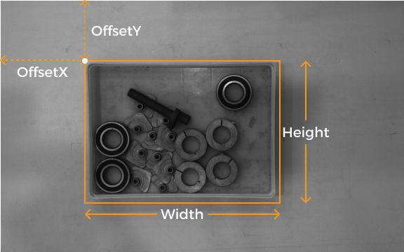
Switch to the Parameters tab and adjust the Height, Width, OffsetX and OffsetY parameters. The following figure shows the four parameters and the capture region defined (orange box) relative to the original image.
-
Width: the width of the capture region
-
Height: the height of the capture region
-
OffsetX: the x-coordinate of the upper-left corner of the capture region (the upper-left corner of the original image being (0, 0))
-
OffsetY: the y-coordinate of the upper-left corner of the capture region
The above four parameters must satisfy the following requirements:
-
(Width + OffsetX) not greater than the width of the original image
-
(Height + OffsetY) not greater than the height of the original image
The width and height of the original image are displayed in the WidthMax and HeightMax parameters under Read-only parameters (Visibility level must be set to Expert or higher).
-
-
-
Acquire data again to see the trimming result.
| If Update Image in the upper right of the Parameters tab is checked, the image in the Graphics Window is automatically updated as you adjust the parameters. |
-
Switch to the Code Generation tab, click Insert Code to generate the corresponding code.
-
If you need to set a capture region for the other data type:
-
Disconnect from the camera in the current image acquisition assistant.
-
Open a new image acquisition assistant, and connect to the camera.
-
Select the other data type and repeat the above steps.
-
|
Comparison of Capture Region and Scan3DROI
Mech-Eye Industrial 3D Camera provides another set of parameters for setting an ROI: Scan3DROILeft, Scan3DROITop, Scan3DROIHeight, and Scan3DROIWidth (collectively referred to as “Scan3DROI”).
The differences between the capture region parameters and Scan3DROI parameters are summarized below. Please select the set of parameters that suit your needs.
| Capture region | Scan3DROI |
|---|---|
Not saved to parameter groups, reset if camera powered off |
Can be saved to parameter groups |
Applicable to 2D image and depth map |
Not applicable to 2D image |
Image is trimmed |
Image not trimmed |
Can only be set in HDevelop |
Can be set with visualized tool in Mech-Eye Viewer |
Adjust Parameters
If the quality of the obtained data is unsatisfactory, you can adjust the camera parameters under the Parameters tab.
|
To adjust the camera parameters, follow these steps:
-
After the camera is connected, click the Parameters tab, set the UserSetSelector parameter to the parameter group that you want to modify.
The parameter group name displayed in HDevelop corresponds to the order of parameter groups in Mech-Eye Viewer. For example, UserSet0 in HDevelop is the first parameter group in Mech-Eye Viewer. For details, please refer to Select Parameter Group in HALCON.
-
Find the UserSetLoad parameter, and click Apply to the right to read in the configuration.
If parameter values are not updated after you click Apply, please click it again.
-
Find the parameter that you want to adjust and change its value.
-
Find the UserSetSave parameter, and click Apply to the right to save the configuration.
-
Switch to the Code Generation tab, click Insert Code to generate the corresponding code.
References
-
The parameters available in GenICam clients generally correspond with those available in Mech-Eye Viewer. For the detailed correspondence, please refer to Camera Parameters Available in GenICam Client.
-
Adjusting camera parameters such as Auto-Exposure ROI, Depth Range and ROI usually requires the assistance of visualized tools for several rounds of fine tuning. Since GenICam clients do not provide visualized tools, you can set these parameters using the visualized tools provided by Mech-Eye Viewer. For details, please refer to Adjust Camera Parameters Using Mech-Eye Viewer.
You must disconnect from the camera in HDevelop before you can connect to it in Mech-Eye Viewer and adjust parameters. If you fail to connect the camera in Mech-Eye Viewer, close HDevelop and try again.