Camera Accuracy
This topic introduces the indicators used to evaluate camera accuracy and factors that may affect camera accuracy.
Evaluate Camera Accuracy
Camera accuracy can be divided into absolute accuracy and repeatability. The following sections introduce these two accuracy indicators.
Absolute Accuracy
The absolute accuracy of a camera evaluates the correctness of the data acquired by the camera. This indicator is tested with reference to the method described in the VDI/VDE 2634 Part 2 standard. The test result is provided as measurement accuracy (VDI/VDE) in the camera technical specifications.
The test method is as follows:
-
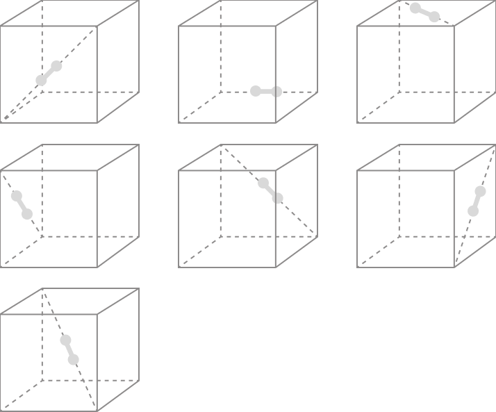
Use a ceramic standard gauge as the target object. The gauge is shaped like a dumbbell, composed of two spheres connected by a short rod.
-
Place the gauge at 7 predetermined positions in a 3D space of predetermined size (as shown below) and acquire the point cloud data of the gauge using the camera at each position.
-
Find the surfaces of the spheres best fit to the point cloud data and calculate the coordinates of the spheres' centers. Then, calculate the distance between the two centers (This is the measured value of the distance between centers).
-
Calculate the difference between the measure value and true value of the distance between centers. Then, divide this difference by the true value of the distance between centers. Use the result as the error of the distance between centers. Take the maximum value in the 7 errors of the distance between centers as the absolute accuracy.

Repeatability
The repeatability of a camera includes the point Z-value repeatability and regional Z-value repeatability. The values are provided in the camera technical specifications.
-
Point Z-value repeatability (1σ): evaluates the repeatability of the depth data (Z-value) of a single pixel acquired by the camera.
The test method is as follows:
-
Use a white ceramic plate with a rough surface that mainly reflects light diffusively as the target object.
-
Acquire the data of the ceramic plate 100 times at different working distances, respectively.
-
For each working distance, calculate the standard deviation of the 100 measured depth values of each pixel in the tested region on the ceramic plate. Take the median of all the standard deviations as the point Z-value repeatability at this working distance.
-
-
Regional Z-value repeatability (1σ): evaluates the repeatability of the depth data of a planar region acquired by the camera. Only UHP-140-GL provides this indicator.
The test method is as follows:
-
Use a white ceramic plate with a rough surface that mainly reflects light diffusively as the target object.
-
Acquire the data of the ceramic plate 100 times at different working distances, respectively.
-
Determine two regions with a size of 200 × 200 pixels on the depth map of the ceramic plate. For the depth map obtained from each acquisition, calculate the average of the depth data within each region, and then calculate the difference between the two averages.
-
For each working distance, calculate the standard deviation of the 100 differences as the regional Z-value repeatability at this working distance.
-
Factors Affecting Camera Accuracy
Camera accuracy may be affected by the following factors:
-
Hardware issues of the camera: The camera as a whole or its components (such as the projector and image sensor) are malfunctioning or damaged. Collisions with other devices can cause camera malfunction or damage.
-
Ambient factors: Factors such as lighting conditions, temperature, humidity, and vibration can affect the performance of the camera. Among these, temperature may lead to thermal drift.
-
Mechanical deformation: If the structure to which the camera is mounted is deformed or wobbles, the camera’s position becomes unstable, which then affects accuracy.
Repeatability also decreases as the working distance increases. Refer to the Point Z-Value Repeatability curves in thecamera technical specifications.
Thermal Drift
Thermal Drift refers to the phenomenon where the change of the camera’s temperature results in change of the coordinate data output by the camera. Under different temperatures, the optical components inside the camera (such as the projector and lenses) change in structure and position due to thermal expansion and contraction. The coordinate data generated based on the principle of triangulation then changes as well.
Temperature changes that lead to thermal drift come from two sources:
-
Interior of the camera: After the camera is connected to power, the components inside will generate heat, which raises the camera’s temperature.
When the ambient temperature remains unchanged, the heat generated inside the camera and the heat dissipated to the surrounding environment will eventually make the camera’s temperature become stable (reaching thermal equilibrium).
-
Surrounding environment: The camera’s temperature changes as the ambient temperature changes.
After the camera reaches thermal equilibrium, if the ambient temperature changes, the camera’s temperature will change again.
Thermal drift affects the absolute accuracy and repeatability of the camera, and as a result, the coordinate data output by the camera may not satisfy the project’s requirements. Please implement the following measures to reduce the influence of thermal drift.
-
Warm up: Before performing hand-eye calibration, checking and correcting the intrinsic parameters, and using the camera to acquire data, use the Warm-Up Tool to warm up the camera first so that it reaches thermal equilibrium.
-
Control ambient temperature: Maintain a stable ambient temperature to avoid the camera’s temperature changing as the ambient temperature changes, which then leads to thermal drift.
-
Deploy the Auto-correct accuracy drift in vision system feature: For 3D vision-guided robotic applications, this feature helps improve the stability and reliability, including addressing thermal drift.