Getting Started
This topic will guide you through the entire process from checking package contents to using Mech-Eye Viewer to capture images.
1. Check Package Contents
-
Make sure that the package is intact when you receive it.
-
Check contents according to the “packing list” in the package to ensure that no devices or accessories are missing or damaged.
| The table below is for reference only. Please take the “packing list” in the package as the final. |
Camera |
|
|---|---|
Accessory box |
|
User manual |
|
DIN rail power supply |
|
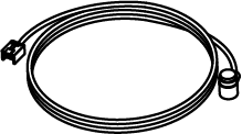
Ethernet cable |
|
DC power cable |
|


2. Check Ports and Indicator Lights
Please refer to the following figures and tables and check the functions of the ports and indicator lights on the camera.

| The figure above is for reference only. The actual product may differ. |
No. |
Name |
Function |
|
|---|---|---|---|
① |
DC 24V port |
1: GND |
2: GND |
3: 24 VDC |
4: 24 VDC |
||
② |
ETH port |
1: MD3_P |
2: MD2_N |
3: MD2_P |
4: MD0_P |
||
5: MD1_P |
6: MD0_N |
||
7: MD3_N |
8: MD1_N |
||
③ |
PWR indicator light |
Off: not connected to power |
|
Green: normal voltage |
|||
Yellow: abnormal voltage, but system is still functioning |
|||
Red: voltage too high or too low, system power is disconnected |
|||
④ |
LINK indicator light |
Off: not connected to network |
|
Blinking green: data being transmitted |
|||
Solid green: no ongoing data transmission |
|||
⑤ |
SYS indicator light |
Off: system not started |
|
Solid green: system starting up |
|||
Blinking green: system operating properly |
|||
Blinking yellow: system operating with error but still functioning |
|||
Blinking red: system not operating |
|||
⑥ |
SCAN indicator light |
Solid: capturing and processing in progress |
|
Off: not capturing or processing |
|||
3. Mount the Camera
| When mounting the camera, please prepare bolts, nuts and wrench of appropriate specifications according to the Dimensions section of the technical specifications for each model. |
Mech-Eye Industrial 3D Camera can be mounted in two ways. Please select the mounting method appropriate for your actual situation.


4. Connect Cables
Please follow these steps to connect the Ethernet and power cables of the camera.
|
4.1. Ethernet Cable
As shown below, insert the M12-A connector of the Ethernet cable to the ETH port on the camera, and insert the RJ45 connector to the Ethernet port on the computer.
4.2. DC Power Cable
As shown below, insert the M12-A connector of the DC power cable to the DC 24V port on the camera.

Connect the M12-A connectors of the cables to the corresponding ports:
-
When inserting, align the bump in the connector with the notch in the port.
-
Tighten the nut. A gap of about 2 mm remains after the nut is fully tightened.

4.3. DIN Rail Power Supply

When wiring the DIN rail power supply, wires of the power cable must be inserted to the corresponding input/output terminals, as shown above.
-
The AC power cable has three wires: L, N, and PE (
 ).
). -
The DC power cable (24V) has three wires: V+, V- and PE (
).
![]() Warning
Warning
-
Please install the DIN rail power supply inside a control cabinet.
-
The DIN rail power supply or the DIN rail should be reliably grounded. If mounting multiple DIN rail power supplies on the same DIN rail, ensure enough distance in between.
-
The stripped part of the PE wire should be as short as possible.
The mounting and connection of the camera hardware is completed. The following sections will introduce how to use Mech-Eye Viewer to connect to the camera and control the camera to capture images.
5. Set IP Addresses
You can download the Mech-Eye SDK installation package from Mech-Mind Download Center.
Decompress the installation package, and then double-click the installer to install Mech-Eye SDK. For more information, please refer to Mech-Eye SDK Installation Guide.
Before connecting to the camera, please make sure that the following IP address are in the same subnet and are unique.
-
Camera IP address
-
The IP address of the IPC Ethernet port connected to the camera
Follow these steps to set the camera IP address:
-
Double-click to open Mech-Eye Viewer.
-
Select the camera to be connected, click
 , and set the camera IP address.
6. Connect to Camera and Upgrade Firmware
-
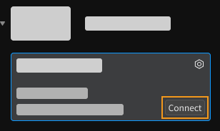
Find the camera to be connected in Mech-Eye Viewer, and click Connect.
-
If the version of the camera firmware is lower than the version of Mech-Eye Viewer, a firmware upgrade message will pop up. Follow these steps to upgrade the camera firmware.
-
Click Yes in the pop-up window, and click Upgrade Firmware in the new pop-up window.
-
Wait for the firmware upgrade to complete and restart the camera according to the instructions.
-
In the upper left of Mech-Eye Viewer, click
 next to Camera List to refresh the list. Repeat until the camera to be connected is displayed again.
 -
Find the camera to be connected and click Connect.
-
7. Capture images
Click ![]() to perform image capturing once.
to perform image capturing once.
|
Clicking |
Click the data types below the image capturing buttons to check the 2D image, depth map and point cloud obtained from the camera.
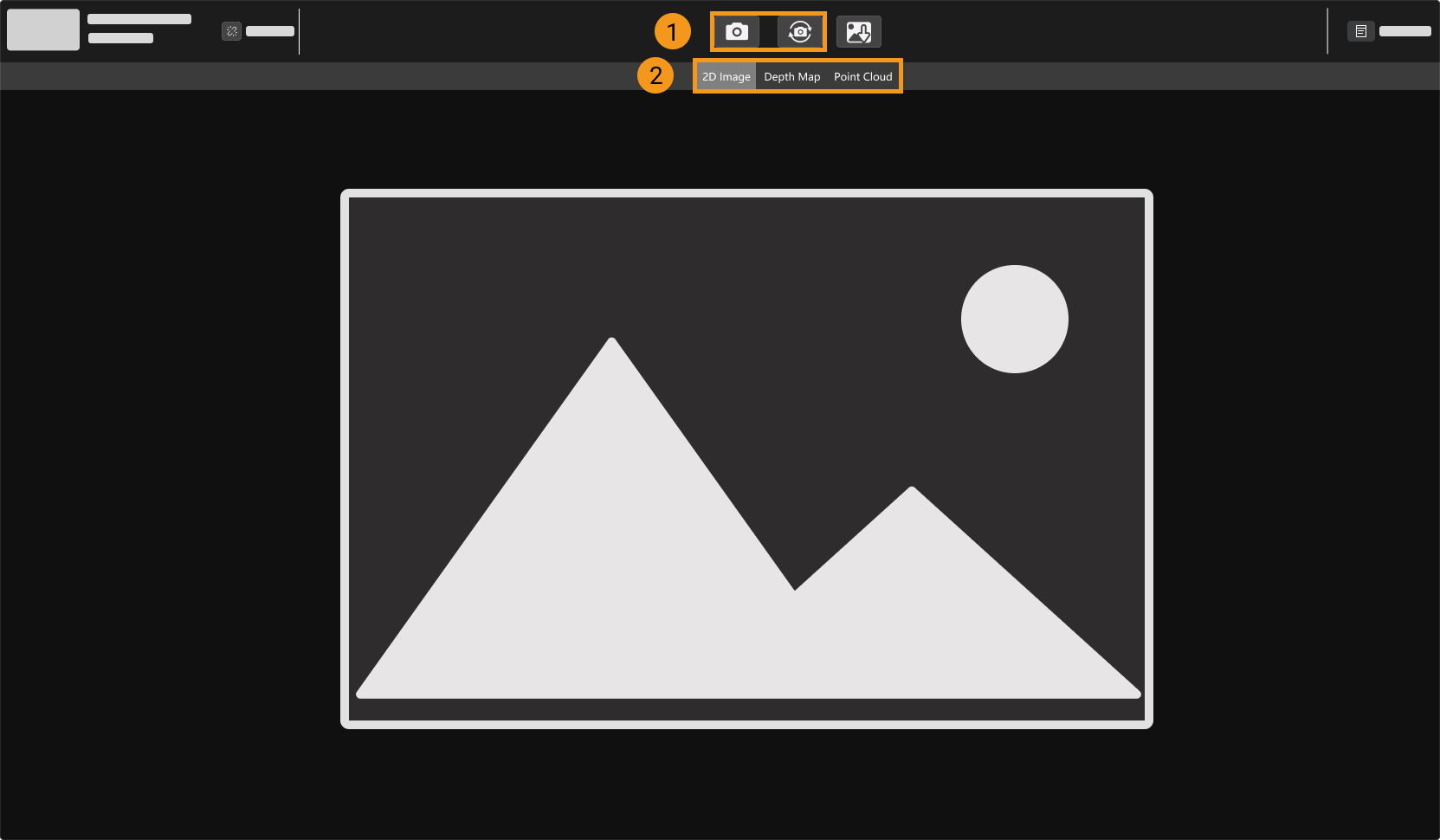
| For more information on image capturing and data types, please refer to Acquire Data and Switch Data Type. |
8. Adjust Parameters
If the quality of the obtained 2D image, depth map and point cloud is not satisfactory, you can adjust the relevant parameters in the parameter panel on the right of the software to improve data quality.
8.1. Determine Data Quality
Based on the following criteria, roughly determine the quality of the obtained data.
-
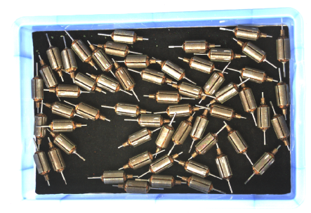
2D image: the 2D image is not too bright or too dark; the surface features of the target object are clearly visible.
Too dark Appropriate Too bright 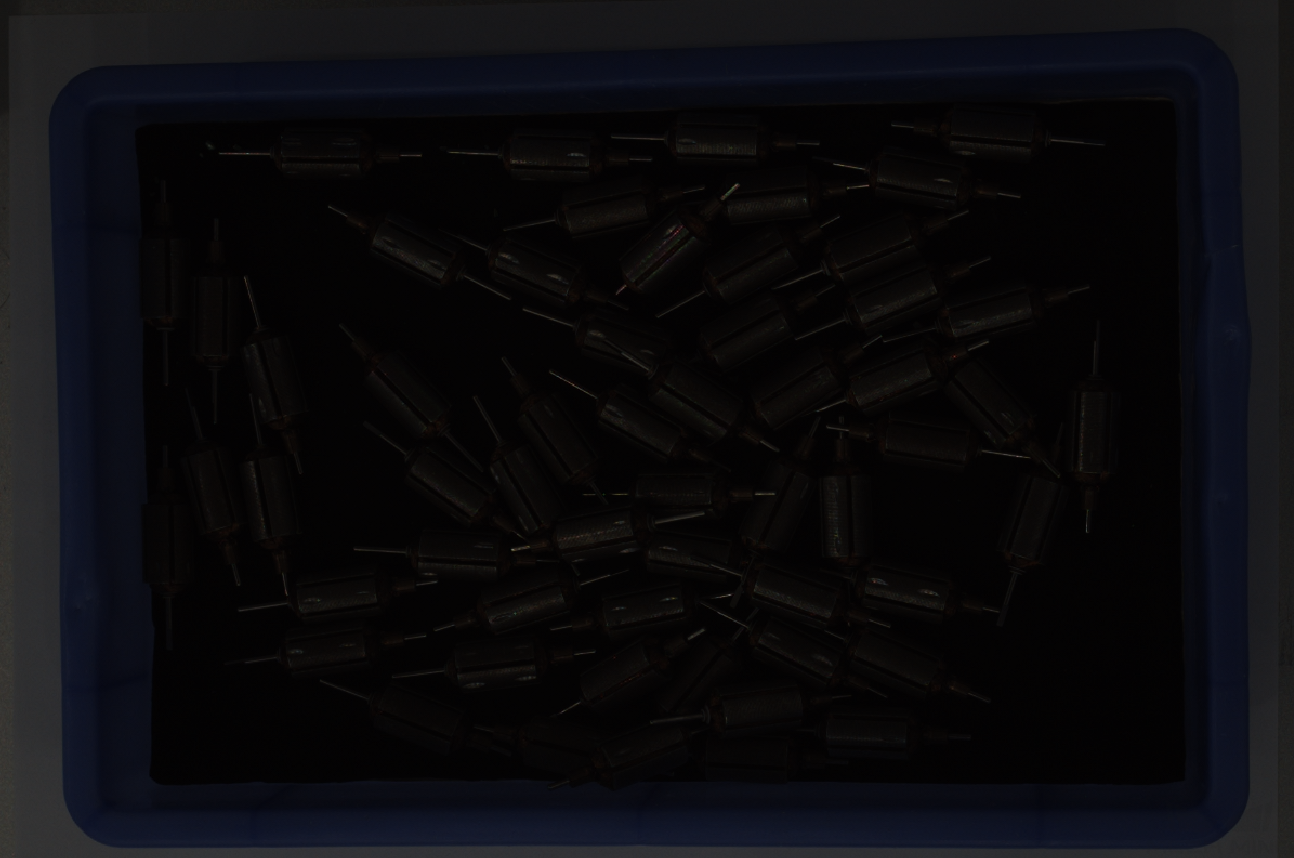
-
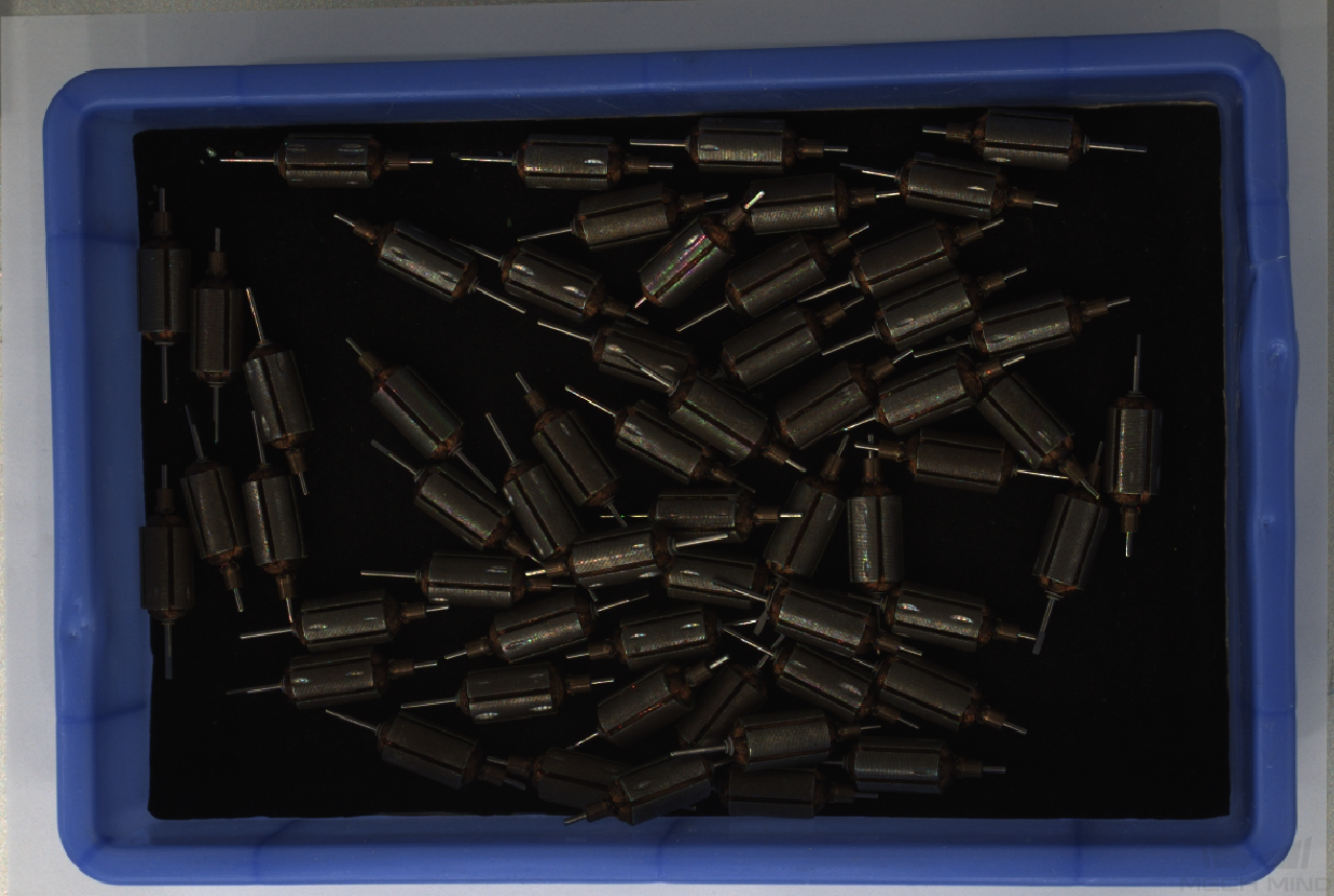
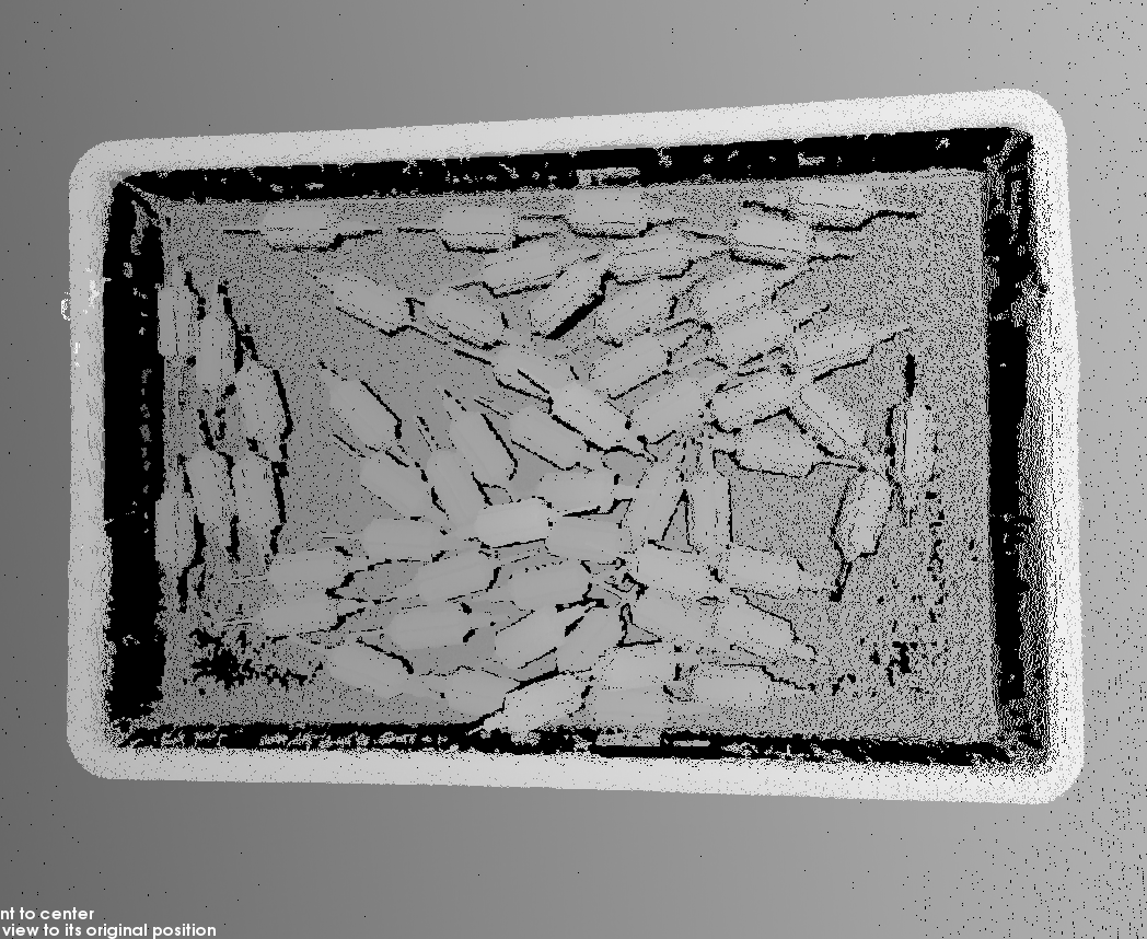
Depth map and point cloud: in the depth map and point cloud, the data corresponding to the target object should be complete. In the following example, the target object is the rotors.
Point cloud of target object incomplete Point cloud of target object complete 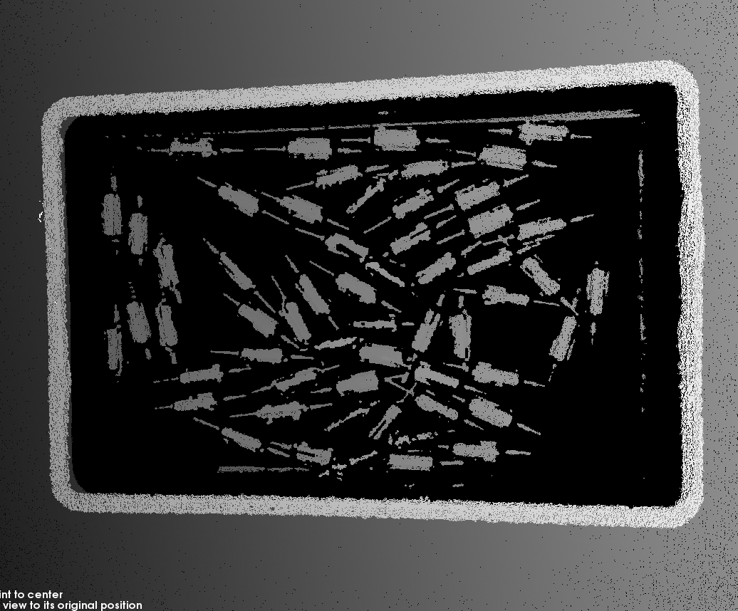
8.2. Improve 2D Image Quality
-
Set the Exposure Mode parameter in the 2D Parameters category to Timed, and then adjust the Exposure Time parameter.
-
If the 2D image is too dark, increase Exposure Time.
-
If the 2D image is too bright, decrease Exposure Time.
DEEP and LSR series provide two types of 2D images corresponding to different parameters. For detailed information, please refer to Parameters of DEEP and LSR Series.
-
-
Capture images again and check the quality of the 2D image.
8.3. Improve Quality of Depth Map and Point Cloud
-
Adjust the Exposure Time parameter in the 3D Parameters category.
-
If the object is dark-colored or not reflective, increase Exposure Time.
-
If the object is light-colored or reflective, decrease Exposure Time.
-
-
Capture images again and check the quality of the depth map and point cloud.
| For more explanations of the parameters, please refer to Parameter Reference Guide. |
9. Use Data
The 2D image, depth map and point cloud obtained through Mech-Eye Viewer can be saved locally or can be output to Mech-Vision or third-party machine vision software for subsequent processing and calculation.
-
Save the data: Click
 in the data acquisition area, set the destination path, check the data types to be saved, and then click Save.
 -
Use the data in Mech-Vision: Please refer to Vision System Tutorial and learn how to build the entire vision system that includes Mech-Vision.
-
Use the data in third-party machine vision software: The data obtained by the camera can be transmitted to third-party software through Mech-Eye API or the GenICam interface.