FAQs and Troubleshooting
FAQs
How to perform calibration on a 7-Axis robot?
|
The 7-axis robots mentioned here do not include 6-axis robots equipped with a sliding rail. |
For ABB, FANUC, KUKA, and YASKAWA 7-axis robots, automatic calibration can be performed through Standard Interface communication after the seventh axis is decoupled.
For other 7-axis robots, you can use the manual calibration method. TCP touch is recommended for calibration.
If no suitable sharp tip is available on-site or the sharp tip cannot be mounted, the multiple random calibration board poses method can be employed. During the calibration process, you need to restrict the movement of one of the axes and idealize the 7-axis robot as a 6-axis robot. The rest of the operations are roughly the same as the calibration on the 6-axis robot.
|
Before hand-eye calibration for 7-axis robots, please check the robot absolute accuracy. |
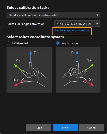
How to calibrate when the Euler angle convention of the robot is uncertain?
When the Euler angle convention of the robot is unknown, use the "Get Euler angle convention" tool on the calibration interface during the pre-calibration configuration. The detailed instructions are as follows:
-
Open Mech-Vision, and click the Camera Calibration button in the toolbar. The Configuration before Calibration window will be prompted.
-
In the Select how to calibrate window, select the New calibration radio button, and then click the Next button.
-
In the Select calibration task window, select Hand-eye calibration for custom robot from the drop-down list box, and click the Get Euler angle convention.
-
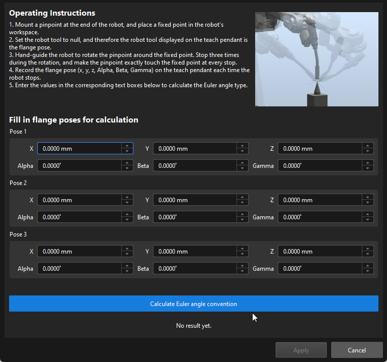
Follow the operating instructions of this tool to record and enter three robot flange poses, and then click Calculate Euler angle convention to get the Euler angle convention of the robot.
What precautions should be taken when checking the intrinsic parameters and correcting them?
For UHP series cameras, the camera1 mode is used to check the intrinsic parameters and perform hand-eye calibration, but the intrinsic parameter correction function cannot be used. If you need to correct the intrinsic parameters, please contact Mech-Mind Technical Support.
When correcting intrinsic parameters:
-
If a LSR series camera is used, the external 2D camera cannot be used in the 1200W mode.
-
If a DEEP-GL camera is used, the depth map cannot be downsampled.
What are the precautions for manual calibration of UR robots?
When perform manual calibration for a UR robot, please note that the Mech-Vision software only supports quaternions or Euler angles when entering poses, while the UR robot’s teach pendant displays rotation vectors. Direct input will lead to abnormal calibration results.
How to perform hand-eye calibration when the robot (hand) and camera (eye) are not in the same field of view for conveyor belt scenarios?
There may be multiple robot arms on the sorting line. For example, the camera is at the infeed end of the conveyor belt, and the robot arm is farther away from the camera (such as six meters later).
In this scenario, please refer to Operation Guide of the TCP Touch Method for hand-eye calibration:
-
The calibration board is placed within the camera’s field of view to acquire images.
-
The calibration board moves along the conveyor line, and the translation distance is recorded.
-
The robot arm uses the TCP tip to touch the calibration board, and the measured value is subtracted by the translation distance mentioned above.
How should hand-eye calibration be performed for column-type robots?
For column-type robots (with four degrees of freedom) where the camera is installed in the ETH mode, if the robot controller can correctly read the TCP tip coordinates, the calibration can be performed by referring to the Process of Calibration for Gantry Robots.
How to read the intrinsic parameter and extrinsic parameter files in the Mech-Vision software?
For more information about how to read the intrinsic parameter check results in the Mech-Eye SDK, as well as the intrinsic parameter and extrinsic parameter files in the Mech-Vision software, please refer to this community post.
Can the robot support automatic calibration if its robot model is not in the robot model library?
Check if the robot brand has adapted to Master-Control communication or Standard Interface communication according to Master-Control Adaptation and Standard Interface Adaptation.
-
If yes, this robot model can support automatic calibration after you created and import the robot model.
-
If not, you can finish configuration to achieve automate calibration through Standard Interface communication according to the FAQ "Whether a robot not adapted to Standard Interface communication can support automatic calibration Standard Interface communication? ".
Why doesn’t the “Automatic” option appear in the Configuration before Calibration window after selecting a robot model?
For robots that have not adapted to Master-Control communication or Standard Interface communication, Mech-Vision supports only manual calibration. Therefore, only the “Manual” option is displayed in the Configuration before Calibration window, while the “Automatic” option is not available.
Please refer to the following information to confirm whether the selected robot brand is adapted to Master-Control communication or Standard Interface communication:
Why doesn’t the “Automatic” option include “Standard Interface communication” for the robot?
If the message “No Standard Interface example program of calibration is available for this robot brand” appears after selecting “Automatic” and “Master-control,” it indicates that the selected robot brand has not adapted to Standard Interface communication. You can also refer to the Standard Interface Adaptation section for confirmation.
If you confirm that the robot brand has adapted to Standard Interface communication, it indicates that there is an issue with the software installation or runtime environment. Follow the steps below to resolve the issue:
-
Check whether you have already used the administrator privilege when installing Mech-Vision & Mech-Viz.
Check method: In the resource tree of Mech-Viz, right-click the robot and select Open Robot File Directory, and return to the root directory of the robot model library “Robot Library 2.x” in Explorer. Check whether the “default_robot_communication_settings.json” file exists.
-
If so, it indicates that the administrator privilege has been used when the software was installed.
-
If not, please reinstall the software with administrator privileges.
-
-
If a firewall has been enabled on the IPC, please confirm whether the software has been added to the firewall whitelist.
-
Check whether the IPC has been added to the domain. Joining a domain may affect the communication function. Please contact your IT administrator for troubleshooting or configuration modification.
Whether a robot not adapted to Standard Interface communication can support automatic calibration Standard Interface communication?
Robots that have not adapted to Standard Interface communication do not support automatic calibration by default. However, you can enable automatic calibration using the following method:
-
Complete the development of the automatic calibration function according to the Standard Interface Development Manual.
-
Modify the communication configuration parameters, so that the “Automatic - Standard Interface” option is available in the Configuration before Calibration window. For detailed instructions, please refer to this community post.
Troubleshooting
Calibration Board Not Detected During Hand-Eye Calibration
Symptom:
During hand-eye calibration with Mech-Vision, the calibration board could not be detected or calibration circles on the calibration board could not be detected.
Affected Software Versions:
All Mech-Vision versions
Solution:
The issue can be solved by performing the following steps:
-
Check whether the calibration board is placed at the center of the camera’s field of view.
-
If yes, proceed to the next step.
-
If no, place the calibration board at the center of the camera’s field of view.
-
-
Check whether the calibration board selection is proper according to Calibration Board Selection.
-
If yes, proceed to the next step.
-
If no, please re-select the appropriate calibration board model.
-
-
Use Mech-Eye Viewer to check whether the camera exposure settings are proper. The 2D and 3D exposure times should be set properly to avoid overexposure and underexposure.
-
If yes, proceed to the next step.
-
If no, readjust the 2D and 3D exposure parameters of the camera. If the scene is too dark, Flash mode (Responsive or Timed) can be selected under Camera 2D Exposure Parameters.
-
-
Check whether the issue is solved by drawing aid circles.
-
If so, the troubleshooting is completed.
-
If no, please contact Mech-Mind Technical Support and inform them that the above items have been checked.
-
Intrinsic Parameter Check Failed During Hand-Eye Calibration
Symptom:
During hand-eye calibration with Mech-Vision, the intrinsic parameter check failed in the “Mount Calibration Board and Check Intrinsic Parameters” step.
Affected Software Versions:
All Mech-Vision versions
Solution:
The issue can be solved by performing the following steps:
-
Please check whether the standard calibration board model selected in this step is consistent with the real model.
-
If yes, proceed to the next step.
-
If no, set the standard calibration board model parameter and check the intrinsic parameters again.
-
-
Please check whether the intrinsic parameter check results meet the intrinsic parameter standards.
-
Please contact Mech-Mind Technical Support for further assistance.
-
If no, go to the next step.
-
-
Check whether the actual working distance of the camera meets the working distance standard.
-
If yes, proceed to the next step.
-
If no, adjust the working distance to a standard range and check the intrinsic parameters again.
-
-
Use Mech-Eye Viewer’s Intrinsic Parameter Tool to check and correct the intrinsic parameters, check the intrinsic parameters again, and then check whether the issue has been resolved.
-
If so, the troubleshooting is completed.
-
If no, please contact Mech-Mind Technical Support.
-
Abnormal Auto-Generated Path Parameters During Automatic Hand-Eye Calibration
Symptom:
During automatic hand-eye calibration with Mech-Vision, the software generated a motion path automatically, but the path parameters were abnormal.
Affected Software Versions:
All Mech-Vision versions
Solution:
The issue can be solved by performing the following steps:
-
Check whether the robot model is correct.
-
If yes, proceed to step 2.
-
If no, proceed to step 4.
-
-
Check whether the calibration board is beyond the camera’s field of view during calibration.
-
If yes, proceed to step 3.
-
If no, continue to the subsequent calibration steps.
-
-
Check whether the calibration board has been moved or rotated manually before calibration.
-
If so, re-execute the entire calibration process.
-
If no, please contact Mech-Mind Technical Support and inform them that the above items have been checked.
-
-
Select the correct robot model in the Robot Communication Configuration window and perform calibration again to check whether the issue has been resolved.
-
If so, the troubleshooting is completed.
-
If no, proceed to step 5.
-
-
Check whether the robot reference frame (base reference frame or flange reference frame) on the robot side is selected correctly.
-
If yes, please contact Mech-Mind Technical Support and inform them that the above items have been checked.
-
If no, select the correct reference frame on the robot side and perform re-calibration.
-
Robot Movement Timeout During Automatic Hand-Eye Calibration
Symptom:
During automatic hand-eye calibration using Mech-Vision, the robot movement timed out.
Affected Software Versions:
All Mech-Vision versions
Solution:
The issue can be solved by performing the following steps:
-
Check whether the robot is moving slowly.
-
If so, improve the robot’s movement speed and re-calibrate the robot.
-
If no, proceed to step 2.
-
-
Check whether non-vision-related errors occur on the robot side.
-
If yes, proceed to step 3.
-
If no, check the robot status and ensure that the robot is in continuous operation mode (either manual continuous run or automatic continuous run).
-
-
Check whether waypoints are unreachable or singularity issues occur on the robot side.
-
If yes, proceed to step 4.
-
If no, please contact Mech-Mind Technical Support, provide a photo of the robot error, and inform them that the above items have been checked.
-
-
Check whether waypoints are unreachable on the robot side.
-
If yes, proceed to step 5.
-
If no, proceed to step 6.
-
-
Check whether the soft limits of the robot model match those of the real robot.
-
If yes, please contact Mech-Mind Technical Support and inform them that the above items have been checked.
-
If no, adjust the soft limits for the robot model and perform re-calibration.
-
-
Check whether singularity issues occur on the robot side.
-
If so, please execute step 7.
-
If no, please contact Mech-Mind Technical Support, provide a photo of the robot error, and inform them that the above items have been checked.
-
-
Change the motion type to joint motion (please pay attention to the collision with scene objects), and re-calibrate to check if the issue has been resolved.
-
If so, the troubleshooting is completed.
-
If no, change the calibration position and perform calibration again.
-
Movement Distance Mismatch Error During Manual Hand-Eye Calibration
Symptom:
During manual hand-eye calibration with Mech-Vision, an error of movement distance mismatch appeared in the “Capture Images and Poses” step.
Affected Software Versions:
All Mech-Vision versions
Solution:
Check whether the robot flange pose input manually is correct.
-
Please contact Mech-Mind Technical Support for further assistance.
-
If no, re-enter the robot flange pose.
Movement Distance Mismatch Error During Automatic Hand-Eye Calibration
Symptom:
During automatic hand-eye calibration with Mech-Vision, an error of movement distance mismatch appeared in the “Capture Images and Poses” step.
Affected Software Versions:
All Mech-Vision versions
Solution:
The issue can be solved by performing the following steps:
-
Check robot accuracy for potential problems (focus on the Z-axis).
-
If yes, please improve the robot accuracy. It mainly involves adjusting the zero position of the robot, setting the robot payload properly, and contacting the robot manufacturer to calibrate the robot accuracy.
-
If no, proceed to step 2.
-
-
Check whether the camera is a V4 camera. A V4 camera refers to a camera whose 10th digit of the serial number is 4.
-
If yes, proceed to step 3.
-
If no, proceed to step 4.
-
-
Check the intrinsic parameters of the camera at different heights, save the raw images of the calibration board, restore the factory intrinsic parameters of the V4 camera ( abnormal accuracy may be caused by incorrect intrinsic parameter correction operations), and then check whether the issue has been resolved.
-
If so, the troubleshooting is completed.
-
If no, use Mech-Eye Viewer’s Intrinsic Parameter Tool to check and correct the intrinsic parameters.
-
-
If it is a camera before the V4 series, check whether the intrinsic parameters of the camera are extremely abnormal.
-
If so, use the Mech-Eye Viewer’s Intrinsic Parameter Tool to check and correct the intrinsic parameters. If the issue still exists, please go to step 5.
-
If no, proceed to step 5.
-
-
Check whether the camera mounting mode is ETH or EIH.
-
In the case of ETH, ensure that the calibration range covers the robot’s working area, and select Calculate Hand-Eye System Compensation (Developer mode must be enabled) when calculating extrinsic parameters. If the issue still exists, please contact Mech-Mind Technical Support.
-
In the case of EIH, please contact Mech-Mind Technical Support.
-
Poor Calibration Results after Hand-Eye Calibration
Symptom:
After the hand-eye calibration was completed successfully, the calibration results were poor, but the calibration board did not deform.
Poor calibration results indicate that the error of 100% of the data points in the point cloud view is greater than the empirical values below.
-
UHP-140-GL: ±0.5 mm
-
PRO S-GL: ± 1 mm
-
NANO ULTRA-GL: ±1.5 mm
-
PRO M-GL: ±2 mm
-
LSR L-GL:±4 mm
-
DEEP-GL: ±5 mm
Affected Software Versions:
All Mech-Vision versions
Solution:
If the calibration result exceeds the empirical value a little, you can resolve the issue as follows:
-
Check whether the calibration board is shaking.
-
If so, secure the calibration board and perform calibration again.
-
If no, go to the next step.
-
-
Check robot accuracy for potential problems.
-
If yes, please improve the robot accuracy. It mainly involves adjusting the zero position of the robot, setting the robot payload properly, and contacting the robot manufacturer to calibrate the robot accuracy.
-
If no, go to the next step.
-
-
Check whether the camera exposure parameters are proper. Adjust the exposure parameters as follows.
-
Disable gain, use a single exposure, and set 3D exposure appropriately to address overexposure and overexposure issues. Overexposure and overexposure not only lead to point cloud loss, but also cause point cloud fluctuation to increase, which affects the calibration accuracy.
-
For scenarios that are too dark: Flash mode (Responsive, Timed) can be selected for 2D exposure.
-
Select point cloud smoothing mode: If the point cloud of the calibration board fluctuates greatly in the DEEP-GL or LSR camera, the calibration result is poor. Change the point cloud smoothing mode to “strong”.
-
-
Check whether the issue has been resolved.
-
If so, the troubleshooting is completed.
-
If no, perform re-calibration. Note that the calibration range should be narrower to avoid excessive influence of robot accuracy errors on extrinsic parameter results.
-
If manual calibration is performed and the calibration result exceeds the empirical value a lot, for example, only 15% of the data points have errors that meet the requirements, and the rotation points are red, you can resolve the issue as follows:
-
Check whether the camera mounting method selected is correct (eye to hand or eye in hand). If incorrect, please modify it.
-
Check whether the Euler angle convention is selected correctly. If incorrect, please modify it.
-
Check whether the Rx and Rz values in the input robot flange pose are incorrect. If incorrect, please modify it.
-
Check whether the left-handed and right-handed coordinate systems are selected wrong. If incorrect, please modify it.
-
Check whether the input robot flange pose is correct. If incorrect, please modify it.
-
If the issue still exists after completing the above checks, please save the calibration data and contact Mech-Mind Technical Support.
If individual calibration points in the point cloud viewer are red, you can resolve the issue as follows:
-
Check whether the calibration point marked red is at the edge of the camera’s field of view.
-
If so, the calibration range is inappropriate. Delete the red data and add proper calibration point data manually.
-
If no, go to the next step.
-
-
Check whether the camera exposure parameters are proper. Adjust the exposure parameters as follows.
-
Disable gain, use a single exposure, and set 3D exposure appropriately to address overexposure and overexposure issues. Overexposure and overexposure not only lead to point cloud loss, but also cause point cloud fluctuation to increase, which affects the calibration accuracy.
-
For scenarios that are too dark: Flash mode (Responsive, Timed) can be selected for 2D exposure.
-
Select point cloud smoothing mode: If the point cloud of the calibration board fluctuates greatly in the DEEP-GL or LSR camera, the calibration result is poor. Change the point cloud smoothing mode to “strong”.
-
-
Check whether the issue has been resolved.
-
If so, the troubleshooting is completed.
-
If no, please contact Mech-Mind Technical Support.
-
Calibration Results Verified as Unqualified after Hand-Eye Calibration
Symptom:
After the hand-eye calibration is completed, the calibration results are verified. However, the calibration results are not up to standard. The symptoms are as follows:
-
In Scene Viewer, when checking the alignment between the robot’s point cloud and its model, a large deviation was observed.
-
For the EIH calibration, a significant offset of the calibration board’s point cloud relative to the fixed point was observed in Scene Viewer.
Affected Software Versions:
All Mech-Vision versions
Solution:
If, after EIH calibration, the verification shows that the calibration board’s point cloud has no significant offset relative to the fixed point, please refer to Poor Calibration Results after Hand-Eye Calibration. If the calibration board’s point cloud shows a significant offset relative to the fixed point, you can solve the issue as follows:
-
Check whether the camera has an offset.
-
If yes, reset the offset.
-
If no, go to the next step.
-
-
Check whether the robot is on a sliding rail.
-
If yes, proceed to step 3.
-
If no, proceed to step 4.
-
-
Confirm whether the robot flange pose is coupled with the external axis value.
-
If yes, verify the position from multiple angles to see whether the sliding rail is in the same position.
-
If yes, proceed to step 4.
-
If no, move the sliding rail to the calibration position and perform re-calibration. If the issue still exists, proceed to step 4.
-
-
If no, narrow down the calibration range and perform re-calibration.
-
-
Check whether the robot is a four-axis robot.
-
If yes, proceed to step 5.
-
If no, proceed to step 6.
-
-
Check whether there is any error between the displayed position of the calibration board’s point cloud and the actual position in the Z direction.
-
If no, confirm that the compatibility mode status of the Mech-Vision and Mech-Viz is inconsistent (for example, Mech-Vision is in compatibility mode, while Mech-Viz is not compatibility mode). If not, please make sure that the compatibility mode of the two software is consistent.
-
Check if the calibration and image capturing use the same TCP.
-
If so, check whether the extrinsic parameter file is reloaded.
-
If no, go to the next step.
-
-
Check whether the robot program triggers the image capturing using the flange pose.
-
If yes, check whether the flange pose is used in the calibration configuration. If not, please use the flange pose for re-calibration.
-
If no, modify the image capturing configuration in the robot program to use flange pose.
-
If, after ETH calibration, the verification shows that the robot point cloud does not deviate significantly from the robot model, please refer to Poor Calibration Results after Hand-Eye Calibration. If there is a significant deviation between the robot model and the robot’s point cloud, you can solve the issue as follows:
-
Check whether the camera has an offset.
-
If yes, reset the offset.
-
If no, go to the next step.
-
-
Check whether the robot is on a sliding rail.
-
If yes, proceed to step 3.
-
If no, proceed to step 5.
-
-
Confirm whether the robot flange pose is coupled with the external axis value.
-
If yes, decouple the external axis values and then use the robot frame for hand-eye calibration.
-
If no, verify the position from multiple angles to see if the sliding rails are in the same position. If yes, proceed to step 4. If no, move the sliding rail to the calibration position and perform re-calibration. If the issue still exists, please contact Mech-Mind Technical Support and inform them with the checked items.
-
-
Check whether the robot is a four-axis robot.
-
If yes, proceed to step 5.
-
If no, proceed to step 6.
-
-
Check whether there is any error between the displayed position of the calibration board’s point cloud and the actual position in the Z direction.
-
If no, confirm that the compatibility mode status of the Mech-Vision and Mech-Viz is inconsistent (for example, Mech-Vision is in compatibility mode, while Mech-Viz is not compatibility mode). If not, please make sure that the compatibility mode of the two software is consistent.
-
Check whether the calibration start point and image-capturing point use the same TCP.
-
If so, check whether the extrinsic parameter file is reloaded.
-
If no, go to the next step.
-
-
Check whether the robot program triggers the image capturing using the flange pose.
-
If yes, check whether the flange pose is used in the calibration configuration. If not, please use the flange pose for re-calibration.
-
If no, modify the image capturing configuration in the robot program to use flange pose.
-