Detect and Measure Oblong Hole
Function
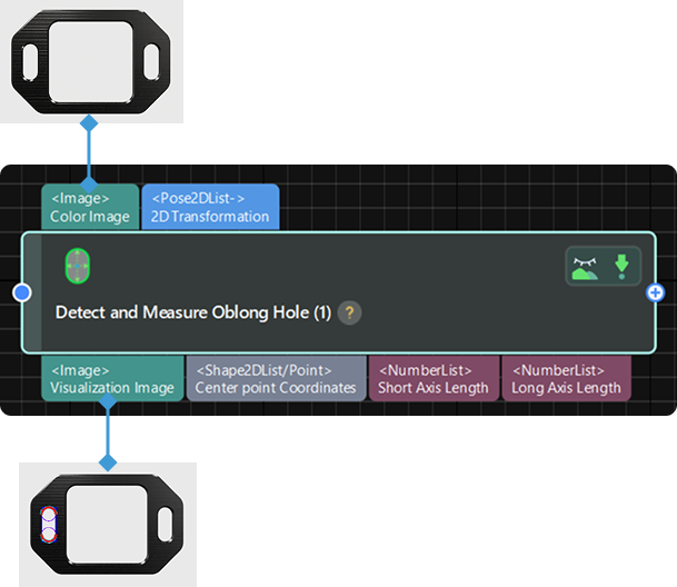
This Step is used to detect and measure oblong holes in the input image.
|
Before using this Step, enable the step_measure2d option under in the menu bar. Only then can the operation be performed. |
Usage Scenario
This Step is used to detect the pixel-wise positions and sizes of oblong holes in images to facilitate subsequent calculation of physical dimensions in measurement scenarios.
Parameter Description
- ROI
-
Description: This parameter is used to specify the region of interest (ROI), which limits the detection and measurement range of an oblong hole.
Instruction: The procedure for using this Step is as follows.
-
Open Measurement Canvas (2D) View: Navigate to in the menu bar, and select the Measurement Canvas (2D) option. Then, switch to the Measurement Canvas (2D) pane within the right Project Configuration Pane.
-
Select the current Step: Click to select the current Step in the Graphical Programming Workspace.
-
Select the region to be detected: In the Measurement Canvas (2D) pane on the right, the selection box is displayed by default in the upper-left corner of the image. It is recommended to zoom the image to an appropriate scale first. Hover the mouse cursor over the selection box. When it changes to a hand icon, press and hold the left mouse button to drag and resize the box.
-
Confirm the ROI parameters: Once the selection is complete, the values of the selected region (Center X, Center Y, Width, Height, and Angle) will be displayed in the ROI parameters.
-
- Position and Orientation Correction
-
Description: This parameter is used to adjust the position and orientation of the ROI according to the input 2D transformation.
Default setting: Unselected
Instruction: If it is selected, the ROl set in the earlier execution will be converted to the position and orientation that fits the object in the image input in the current execution according to the input 2D transformation.
- Canny Edge Detection Low Threshold
-
Description: This parameter is used to set a low threshold for the Canny edge detection algorithm.
Default value: 40
Instruction: Edges with gradients above the high threshold are considered actual edges. Edges with gradients between high and low thresholds are considered actual edges only if they are connected to actual edges with gradients greater than the high threshold. Edges with gradients below the low threshold are ignored. The Sobel operator is used to calculate the gradients, and the maximum of gradients is 255.
- Canny Edge Detection High Threshold
-
Description: This parameter is used to set a high threshold for the Canny edge detection algorithm.
Default value: 100
Instruction: Edges with gradients above the high threshold are considered actual edges. Edges with gradients between high and low thresholds are considered actual edges only if they are connected to actual edges with gradients greater than the high threshold. Edges with gradients below the low threshold are ignored. The Sobel operator is used to calculate the gradients, and the maximum of gradients is 255.
- Sigma of Gaussian Filter
-
Description: This parameter is used to filter the image vertically within the edge detection frames.
Default value: 1.0
Tuning recommendation: It is recommended to use the default value.
- Edge Transition Type
-
Description: This parameter is used to specify which type of grayscale change will be considered as object edge points. The grayscale change is defined as the grayscale change vertically from top to bottom in an edge detection frame.
Value list: White To Black, Black To White, Both
-
White to Black: The grayscale changes from white to black in the frames will be considered points on object edges.
-
Black to White: The grayscale changes from black to white in the frames will be considered points on object edges.
-
Both: The grayscale changes both from black to white and from white to black in the frames will be considered points on object edges.
Default value: Both
-
- Edge Selection
-
Description: This parameter is used to select edge points detected within the edge detection frame for fitting the complete edge.
Value list: First, Second, Last, All
-
First: The first point from top to bottom in the frame will be selected for fitting.
-
Second: The second point from top to bottom in the frame will be selected for fitting.
-
Last: The last point from top to bottom in the frame will be selected for fitting.
-
All: All the points in the frame will be selected for fitting.
Default value: First
-