Select Calibration Spheres
In this topic, we will explain how to determine the number and diameter of calibration spheres based on the camera in use before deploying the vision system accuracy drift correction solution.
After determining the diameter of the calibration sphere, you can refer to Calibration Sphere User Guide for usage guidance and maintenance information.
|
In general, the vision system accuracy drift auto-correction solution can be deployed regardless of the camera model used in the vision system. If the camera working distance is between 500 mm and 3000 mm, a 60 mm-diameter calibration sphere can be used directly. If the camera working distance is outside the 500–3000 mm range, please contact Technical Support to evaluate the use of calibration spheres with other specifications. |
Auto-Correct Accuracy Drift in EIH Vision System
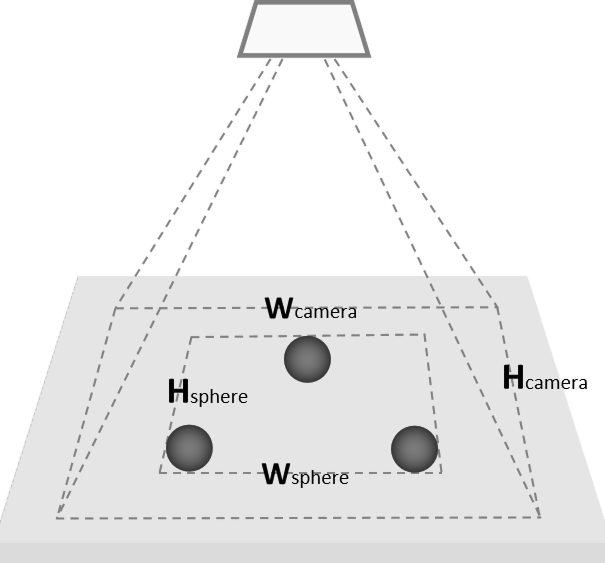
Before deploying the solution, prepare 3 calibration spheres. The table below shows how to determine the corresponding calibration sphere diameter and the sphere’s bounding rectangle dimensions based on the camera model and field of view.
| Camera model | Camera FOV (mm) | Calibration sphere diameter (mm) | Calibration sphere bounding rectangle dimension Wsphere × Hsphere (mm) |
|---|---|---|---|
UHP-140-GL |
Near FOV 135 × 90 @ 0.28 m |
25.4 |
94 × 62 @ 0.28m |
Far FOV 150 × 100 @ 0.32 m |
25.4 |
105 × 70 @ 0.32 m |
|
NANO-GL |
Near FOV 220 × 150 @ 0.3 m |
25.4 |
154 × 105 @ 0.3 m |
Far FOV 440 × 300 @ 0.6 m |
60 |
308 × 210 @ 0.6 m |
|
NANO ULTRA-GL |
Near FOV 220 × 165 @ 0.25 m |
25.4 |
154 × 115 @ 0.25 m |
Far FOV 500 × 340 @ 0.5 m |
60 |
300 × 204 @ 0.5 m |
|
PRO S-GL |
Near FOV 370 × 240 @ 0.5 m |
60 |
222 × 144 @ 0.5 m |
Far FOV 800 × 450 @ 1.0 m |
60 |
480 × 270 @ 1.0 m |
|
PRO M-GL |
Near FOV 800 × 450 @ 1.0 m |
60 |
480 × 270 @ 1.0 m |
Far FOV 1500 × 890 @ 2.0 m |
60 |
900 × 534 @ 2.0 m |
|
LSR S-GL |
Near FOV 480 × 360 @ 0.5 m |
60 |
288 × 216 @ 0.5 m |
Far FOV 1500 × 1200 @ 1.5 m |
60 |
900 × 720 @ 1.5 m |
|
For the ratio between the calibration sphere’s bounding rectangle side length and the camera’s field-of-view side length, you can refer to the following information:
|
Auto-Correct Accuracy Drift in ETH Vision System
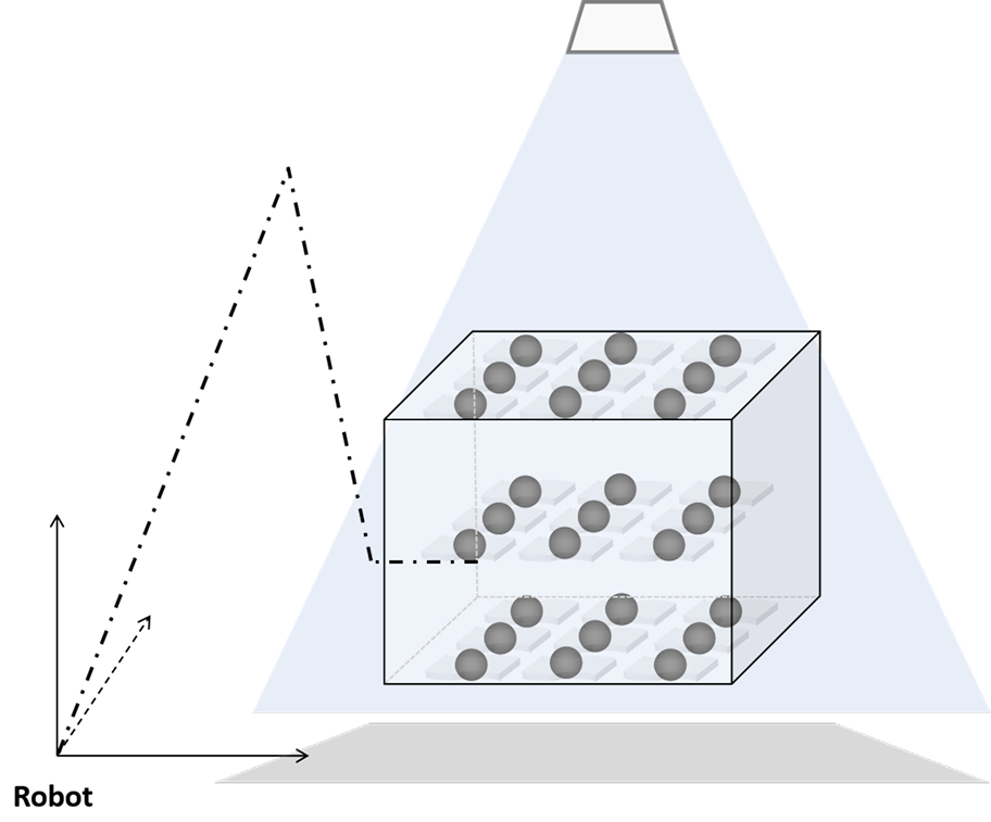
Before deploying the solution, prepare 1 calibration spheres. The table below shows how to determine the corresponding calibration sphere diameter and its motion range based on the camera model and field of view.
| Camera model | Camera FOV (mm) | Calibration sphere diameter (mm) | Motion range when carried by robot |
|---|---|---|---|
LSR S-GL |
Near FOV 480 × 360 @ 0.5 m |
60 |
Entire bin space |
Far FOV 1500 × 1200 @ 1.5 m |
60 |
Entire bin space |
|
LSR L-GL |
Near FOV 1200 × 1000 @ 1.2 m |
60 |
Entire bin space |
Far FOV 3000 × 2400 @ 3.0 m |
100 |
Entire bin space |
|
LSR XL-GL |
Near FOV 1280 × 1280 @ 1.6 m |
60 |
Entire bin space |
Far FOV 3000 × 2800 @ 3.5 m |
100 |
Entire bin space |
|
DEEP-GL |
Near FOV 1200 × 1000 @ 1.2 m |
60 |
Entire bin space |
Far FOV 3500 × 2800 @ 3.5 m |
100 |
Entire bin space |