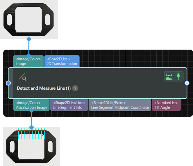
Detect and Measure Line
Function
This Step is used to detect and measure line segments in the input image.
|
Before using this Step, enable the step_measure2d option under in the menu bar. Only then can the operation be performed. |
Usage Scenario
This Step is used to detect the pixel-wise positions of object edge line segments in images to prepare for subsequent calculation of physical dimensions in measurement scenarios.
Parameter Description
- ROI
-
Description: This parameter is used to specify the region of interest (ROI), which limits the detection and measurement range of a line segment.
Instruction: The procedure for using this Step is as follows.
-
Open Measurement Canvas (2D) View: Navigate to in the menu bar, and select the Measurement Canvas (2D) option. Then, switch to the Measurement Canvas (2D) pane within the right Project Configuration Pane.
-
Select the current Step: Click to select the current Step in the Graphical Programming Workspace.
-
Select the region to be detected: In the Measurement Canvas (2D) pane on the right, the selection box is displayed by default in the upper-left corner of the image. It is recommended to zoom the image to an appropriate scale first. Hover the mouse cursor over the selection box. When it changes to a hand icon, press and hold the left mouse button to drag and resize the box.
-
Confirm the ROI parameters: Once the selection is complete, the values of the selected region (Center X, Center Y, Width, Height, and Angle) will be displayed in the ROI parameters.
-
- Position and Orientation Correction
-
Description: This parameter is used to adjust the position and orientation of the ROI according to the input 2D transformation.
Default setting: Unselected
Instruction: If it is selected, the ROl set in the earlier execution will be converted to the position and orientation that fits the object in the image input in the current execution according to the input 2D transformation.
- Number of Edge Detection Frames
-
Parameter description: This parameter is used to set the number of edge detection frames generated within the set ROI. Object edge points used for fitting will be generated within each edge detection frame. The larger the value, the denser the edge point sampling and the higher the fitting accuracy; however, this also increases the computational load. If the value is too small, edge details may be lost.
Default value: 10
Instruction: Set the parameter according to the actual requirement.
- Grayscale Change Lower Threshold
-
Description: This Step is used to set the lower threshold of the grayscale change of the point in the edge detection frames.
Default value: 20
Instruction: Points within edge detection frames are considered object edge points when their grayscale gradient changes exceed the set lower threshold; when the gradient changes fall below the threshold, they are ignored.
- Edge Detection Frame Half Width
-
Description: This parameter is used to set the half width of the edge detection frame.
Default value: 1
Instruction: Increase the value when the edge is unclear; decrease it appropriately when the edge is clear.
- Sigma of Gaussian Filter
-
Description: This parameter is used to filter the image vertically within the edge detection frames.
Default value: 1.0
Tuning recommendation: It is recommended to use the default value.
- Edge Polarity Type
-
Description: This parameter is used to specify which type of grayscale change will be considered as object edge points. The grayscale change is defined as the grayscale change vertically from top to bottom in an edge detection frame.
Value list: White To Black, Black To White, Both
-
White to Black: The grayscale changes from white to black in the frames will be considered points on object edges.
-
Black to White: The grayscale changes from black to white in the frames will be considered points on object edges.
-
Both: The grayscale changes both from black to white and from white to black in the frames will be considered points on object edges.
Default value: Both
-
- Edge Selection
-
Description: This parameter is used to select edge points detected within the edge detection frame for fitting the complete edge.
Value list: First, Second, Last, All
-
First: The first point from top to bottom in the frame will be selected for fitting.
-
Second: The second point from top to bottom in the frame will be selected for fitting.
-
Last: The last point from top to bottom in the frame will be selected for fitting.
-
All: All the points in the frame will be selected for fitting.
Default value: First
-
- Fitting Method
-
Description: This parameter is used to specify the type of algorithm for line fitting.
Value list: Least Squares, Huber
-
Least Squares: This method fits the line by minimizing the sum of squared deviations of all points from the line. It offers high computational efficiency and is suitable for scenarios where edge points are evenly distributed with few outliers, but it is sensitive to anomalies. It is recommended to select this option when the edge points are evenly distributed and there is less noise.
-
Huber: A robust fitting method that behaves similarly to the least squares method when the deviation is small, but can effectively suppress the influence of outliers when the deviation is large. It is recommended to select this method when edge point quality is low or outliers are present in the image.
Default setting: Huber
-
Visualization Settings
- Draw ROI
-
Description: This parameter is used to determine whether to display the centerline of the manually selected ROI on the image, which indicates the generation path and direction of the edge detection frames.
Default setting: Selected
Instruction: When enabled, the centerline is displayed as a dark blue arrowed line segment. Display can be toggled as needed.
- Draw Edge Detection Frames
-
Description: This parameter is used to determine whether to display the edge detection frames used for extracting edge points on the image. Edge detection frames are generated along the centerline within the manually selected ROI and arranged perpendicular to the centerline to extract grayscale changes within these frames.
Default setting: Selected
Instruction: When enabled, the edge detection frames are displayed as light blue vertical line segments. Display can be toggled as needed.
- Draw Edge Points
-
Description: This parameter is used to determine whether to display the object edge points used for fitting on the image. Object edge points are detected through grayscale changes in the edge detection frames.
Default setting: Selected
Instruction: When enabled, edge points are displayed in red. Display can be toggled as needed.
- Draw Detected Line Segment
-
Description: This parameter is used to determine whether to display the detected line segment in the ROI on the image.
Default setting: Selected
Instruction: When enabled, the line segment is displayed in green. Display can be toggled as needed.