Set up Standard Interface Communication with TOPSTAR
This guide shows how to load the Standard Interface program files to an TOPSTAR robot, and set up the Standard Interface communication between Mech-Mind Vision System and the robot.
| In this section, you will load the robot Standard Interface program and the configuration files to the robot system to establish the Standard Interface communication between the vision system and the robot. |
Preparation
Check Controller and Software Compatibility
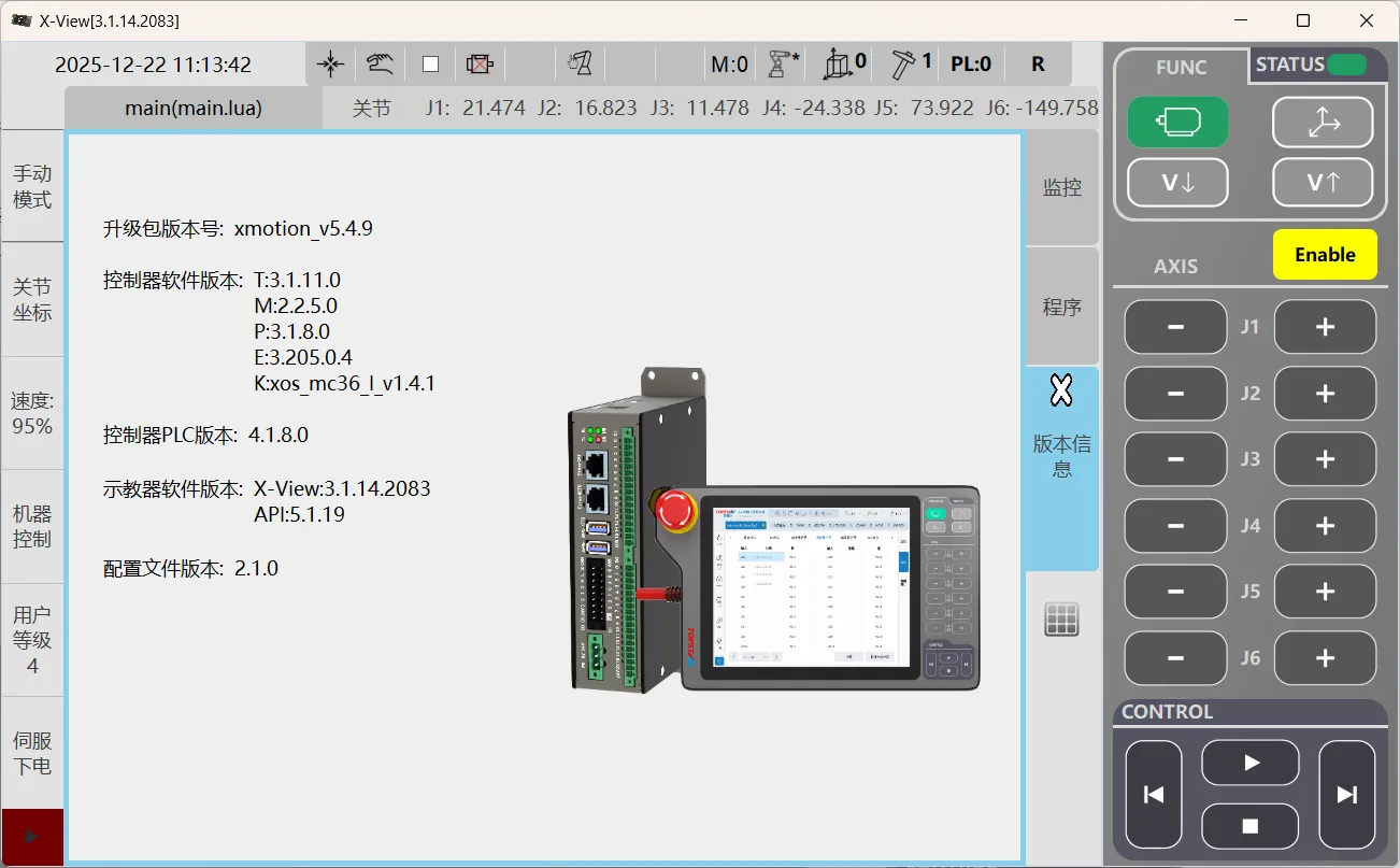
Controller Version:
-
T: 3.1.11.0
-
M: 2.2.5.0
-
P: 3.205.0.4
-
K:xos_ms36_l_v1.4.1
Teach Pendant Version: X-View: 3.1.14.2083
Procedure for checking version information:
-
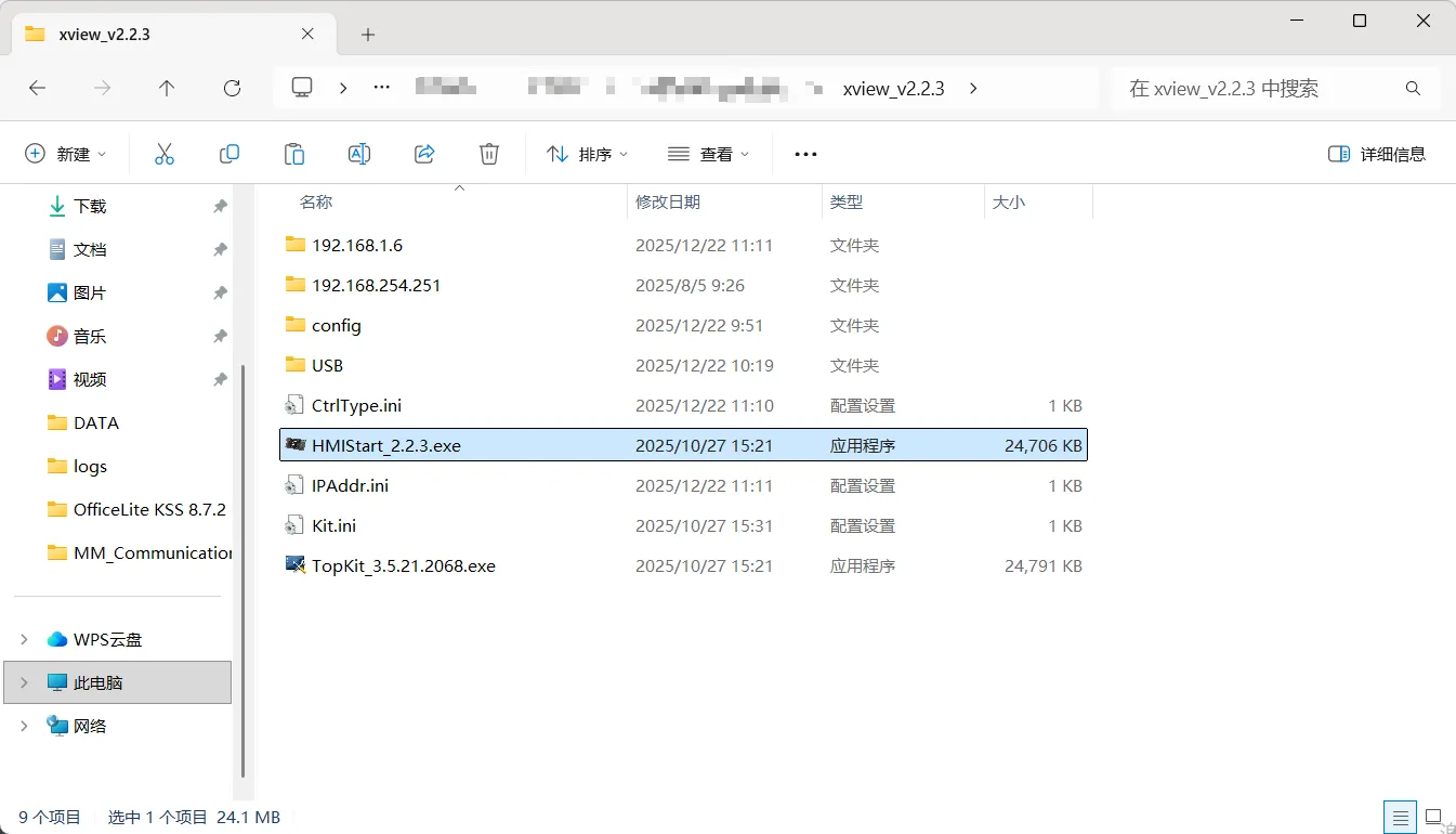
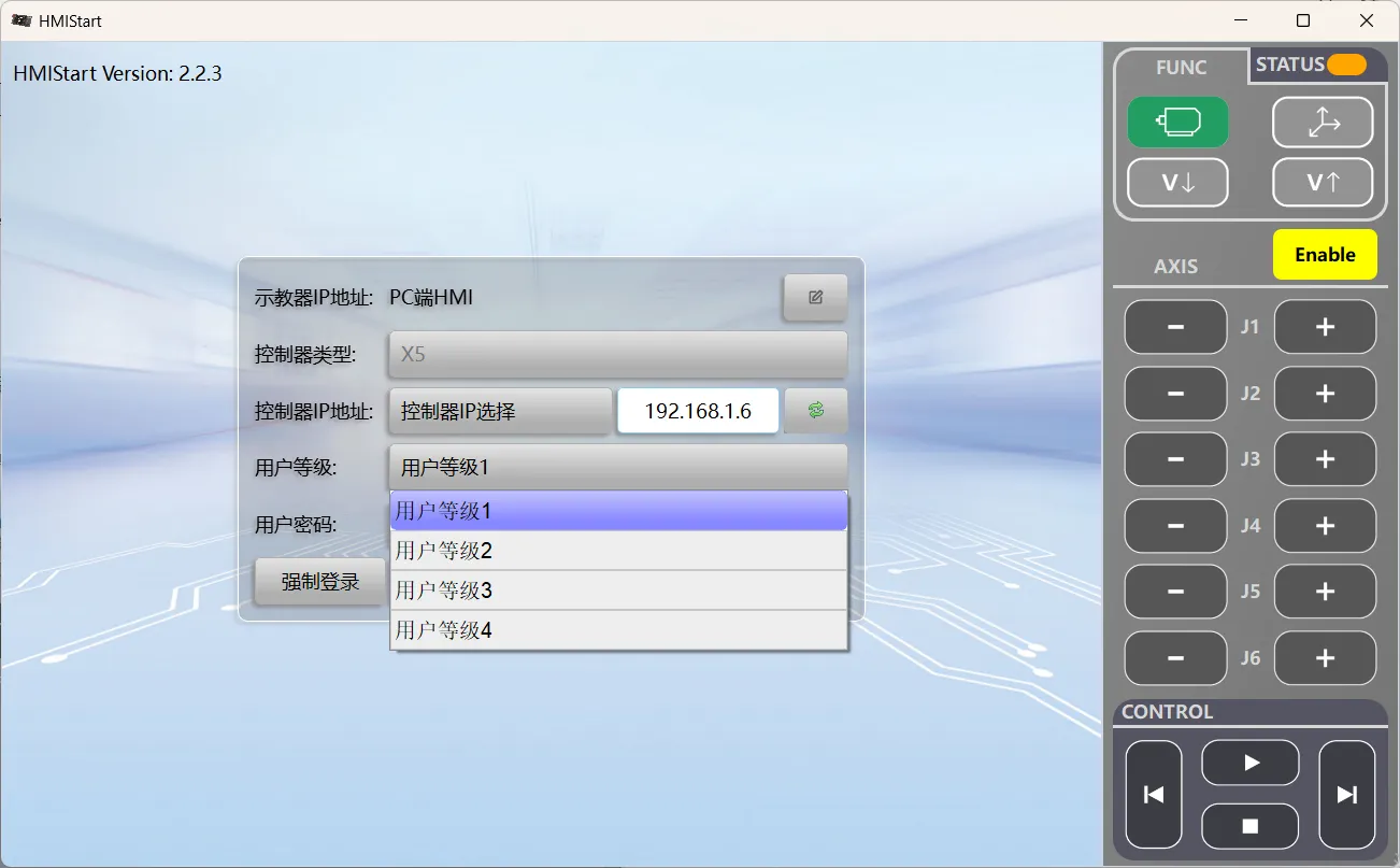
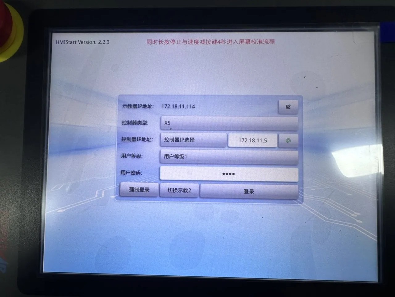
Launch the X-View robot interface software (using version v2.2.3 as an example).
-
From the User Level drop-down list, select User Level 4.
-
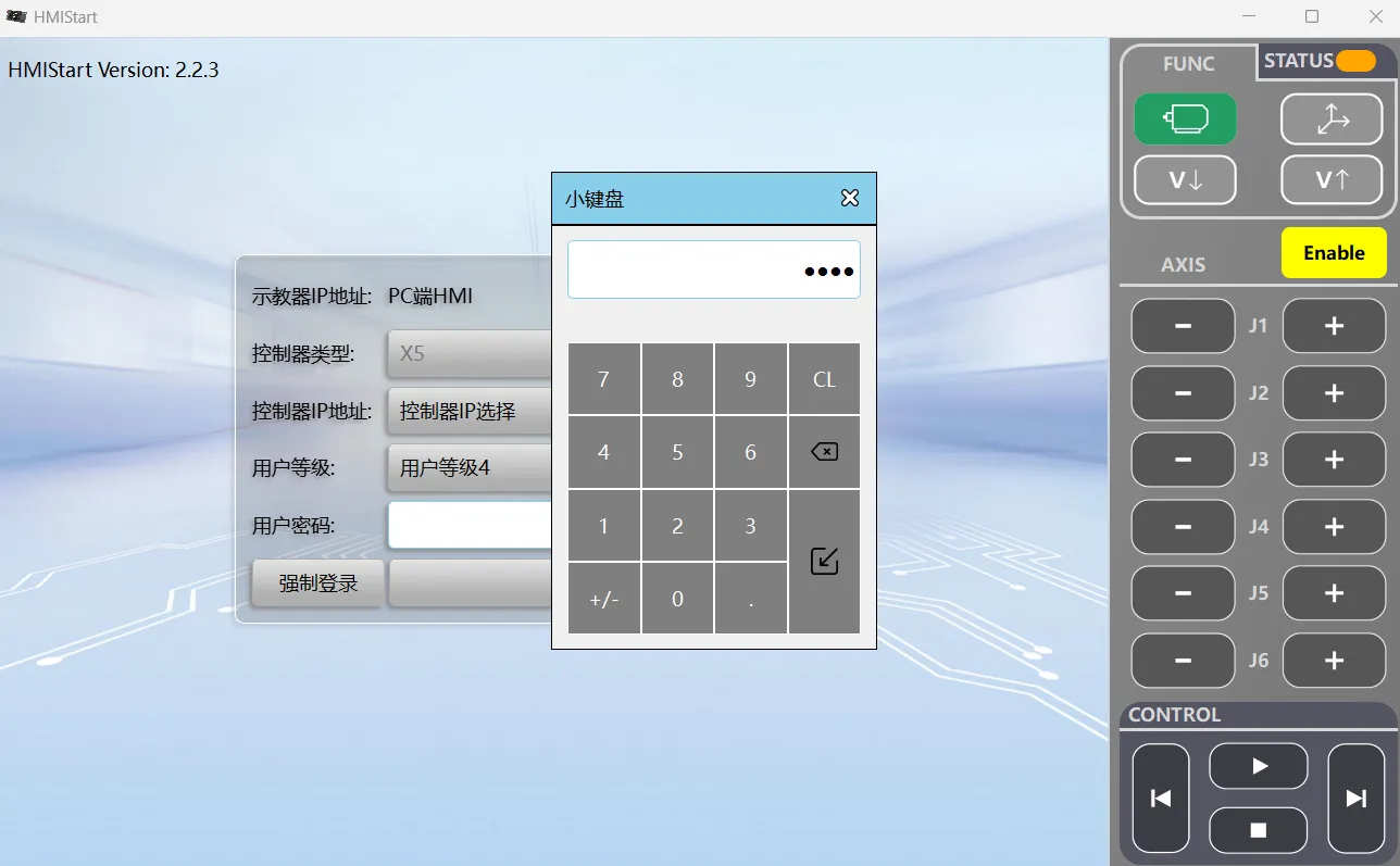
Enter the password 0920.
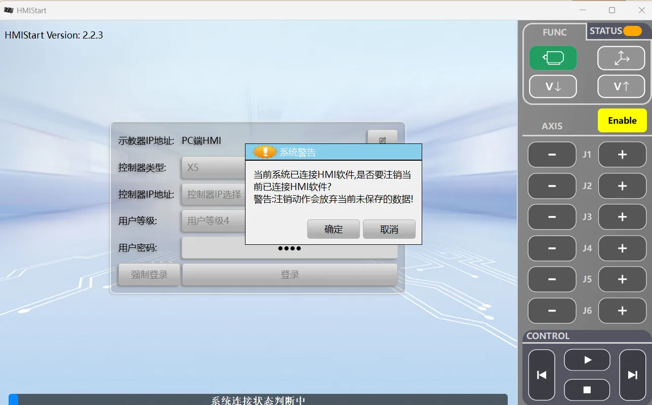
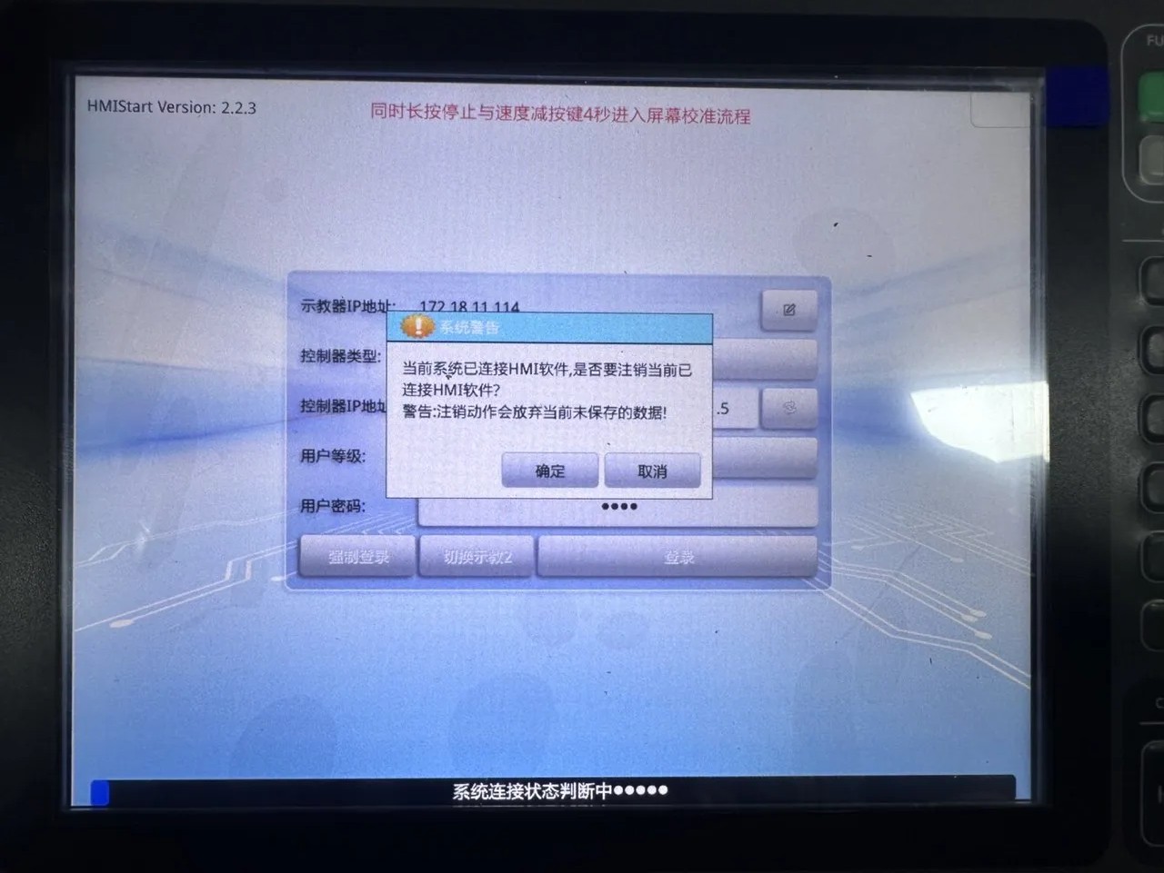
If a System Warning dialog box appears, click OK.
-
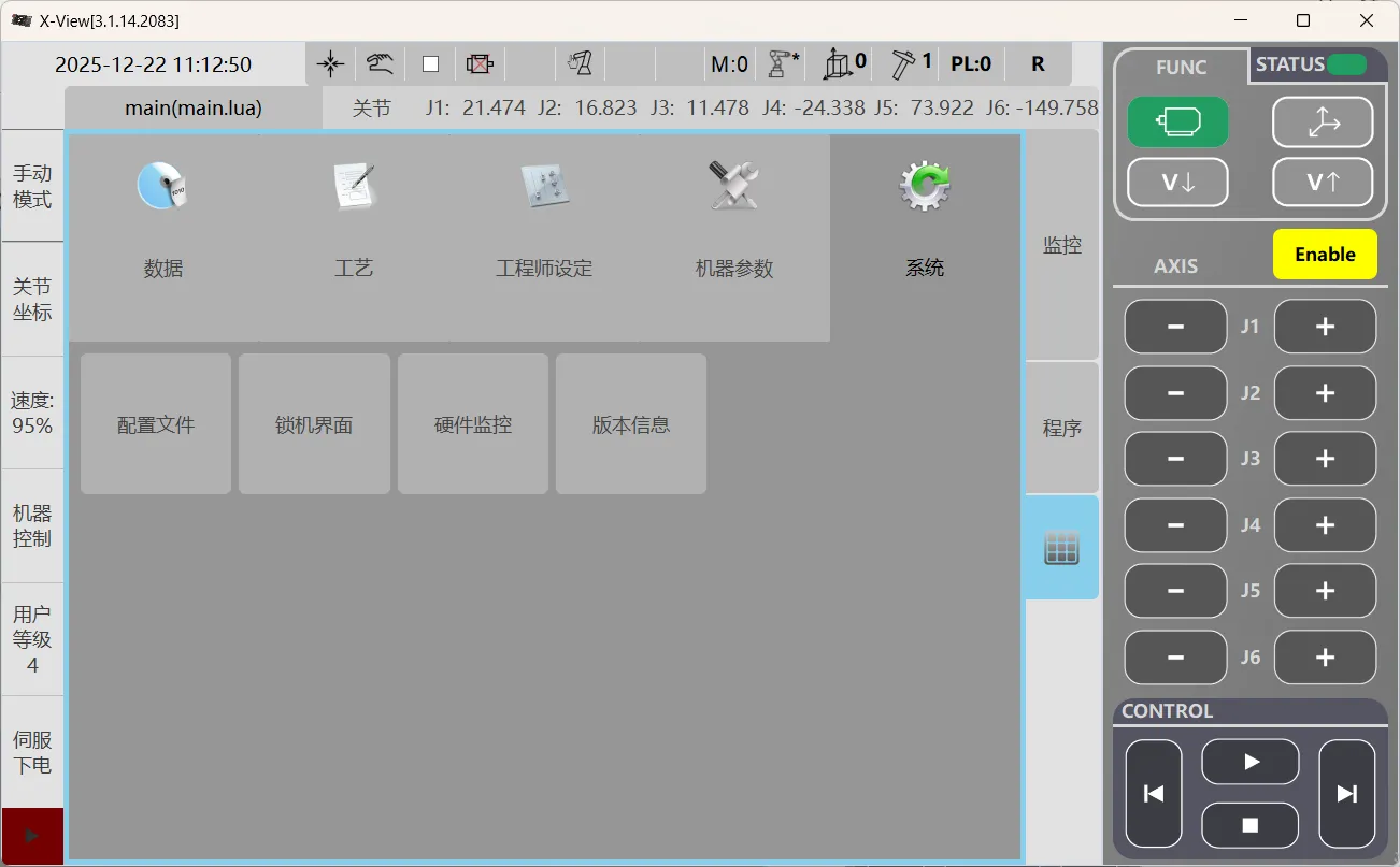
Click Square Grid to enter the main interface, select the System module, and then click Version.
-
Open the page to view the software and hardware version information.
Set up the Network Connection
Connect the Hardware
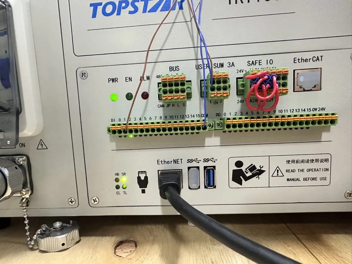
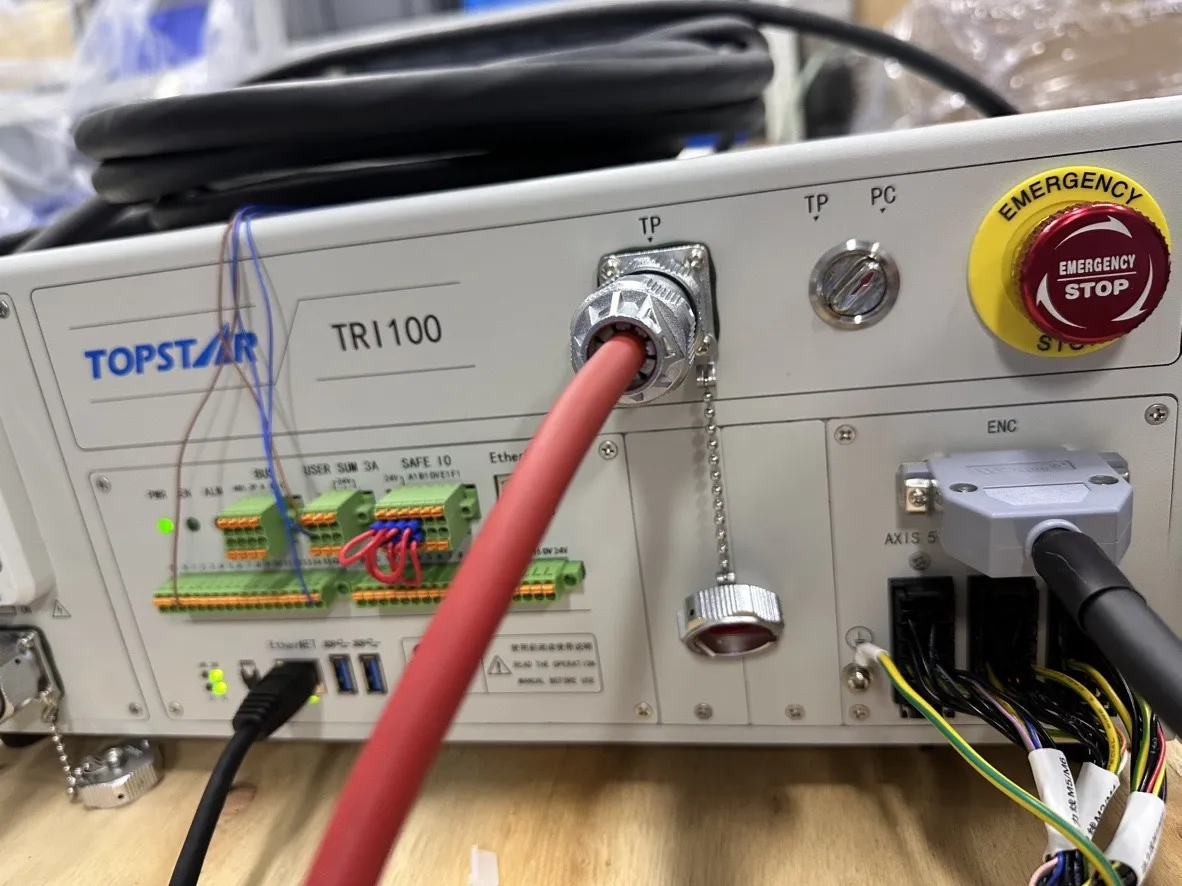
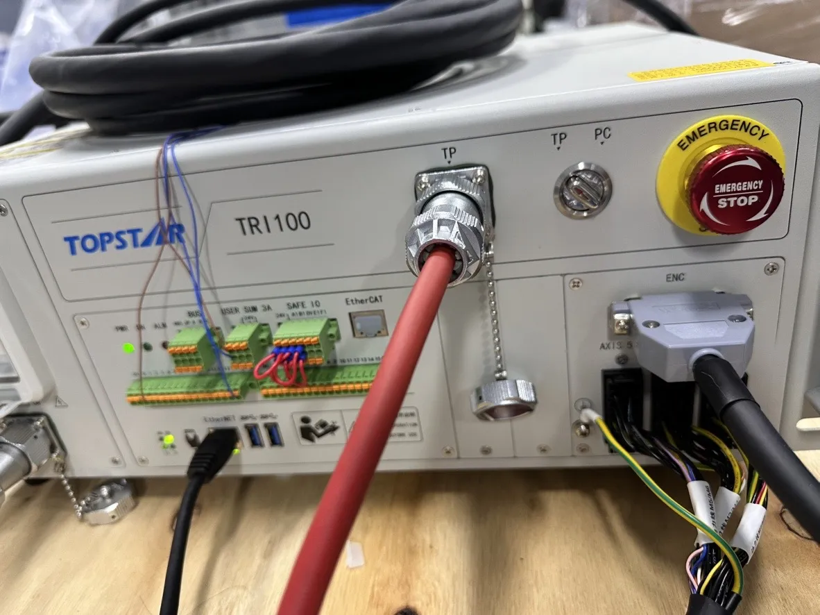
Insert one end of the network cable into the industrial PC’s network port and the other end into the robot controller cabinet motherboard’s Ethernet port, as shown in the figure below:
|
When connecting the industrial PC, you must use the Ethernet port; do not connect the network cable to the EtherCAT port! |
Set the IP Address
Establish a network connection via the X-View as follows:
-
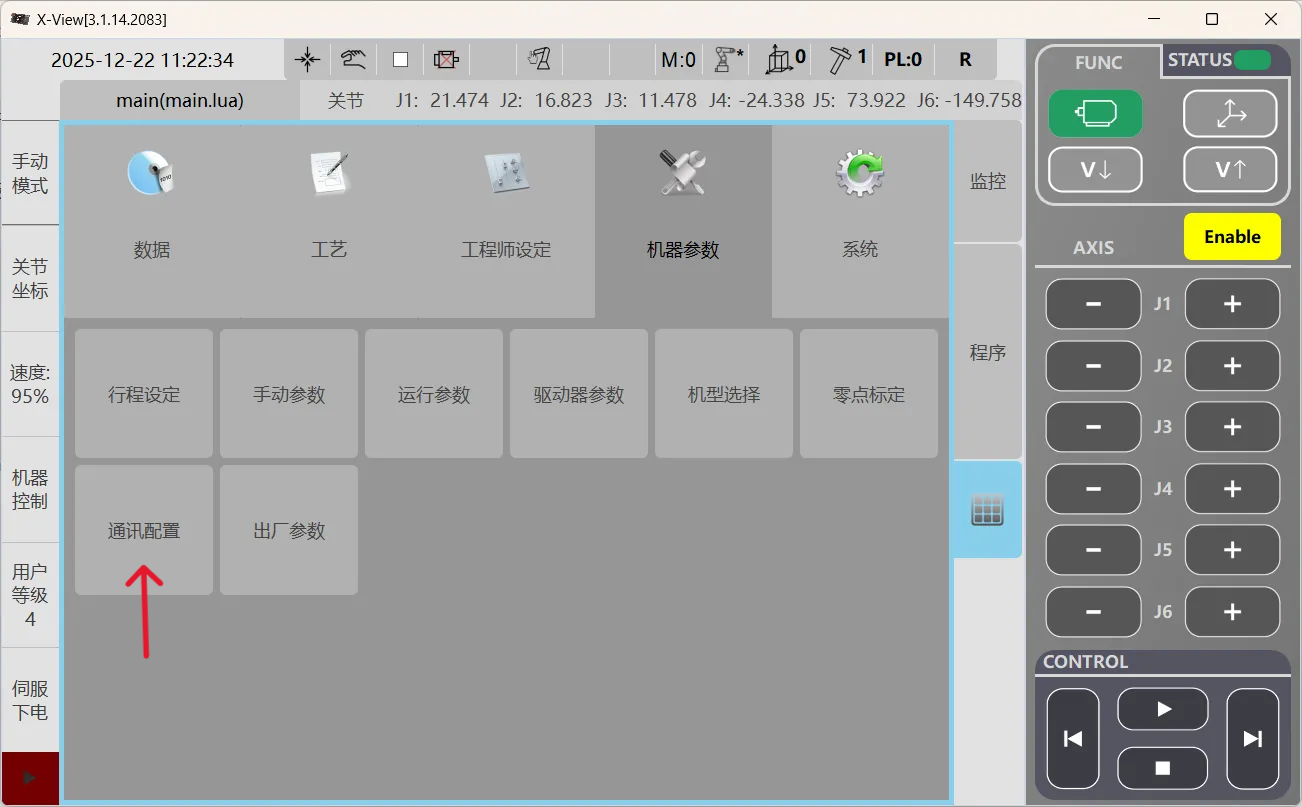
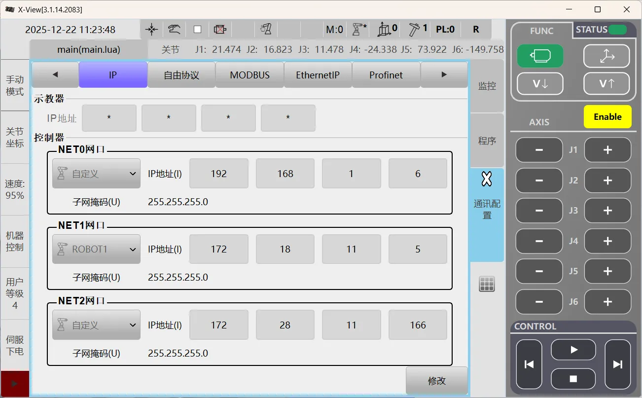
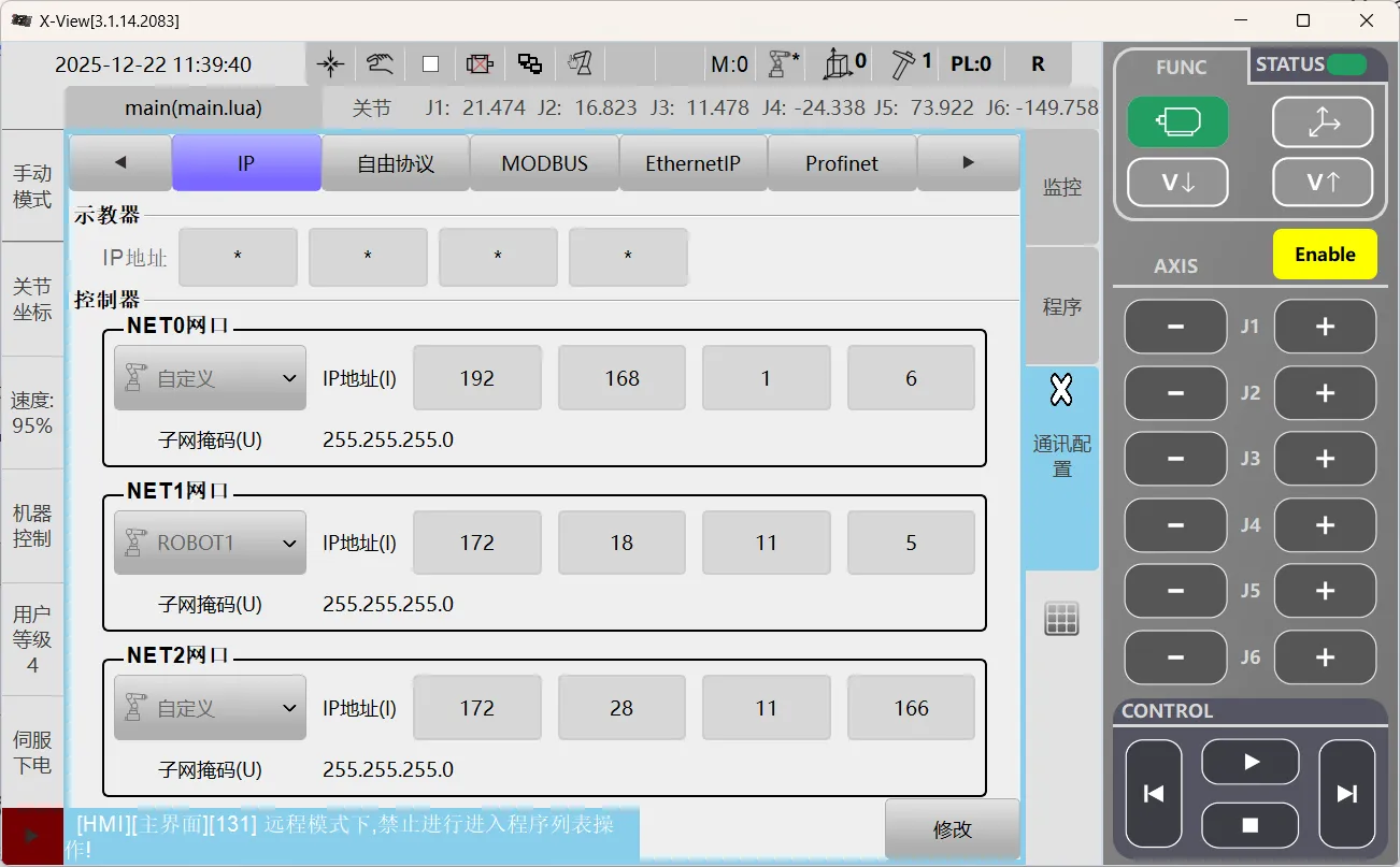
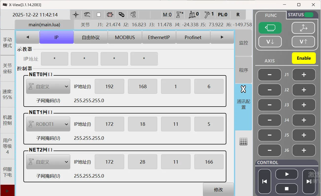
Launch the X-View, click Square Grid to enter the main interface, select the Robot Params module, then click Comm..
-
Go to the Comm. page. Under IP options, in the Control section, set the robot’s IP address to be on the same subnet as the industrial PC.
Back up Robot Program Files
PC Mode Backup
-
Turn the control cabinet selector switch to PC Mode.
-
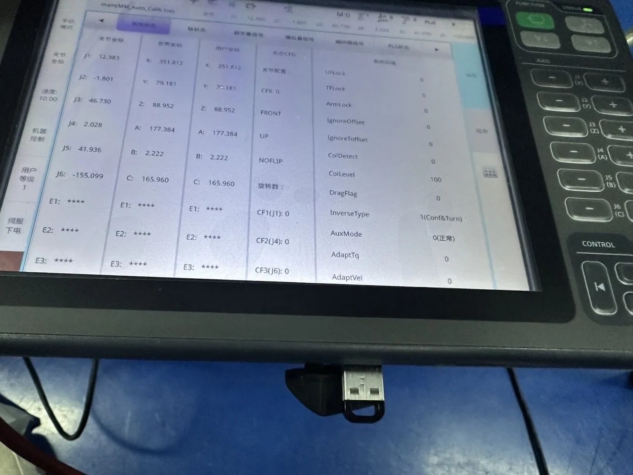
Launch the X-View software, then select and switch to Manual Mode from the left sidebar menu.
-
Select the programs to be backed up, then click the Export button at the bottom.
-
In the pop-up dialog box, modify the exported program name (if necessary), then click OK to export the program as a backup.
TP Mode Backup
-
Turn the control cabinet selector switch to TP Mode.
-
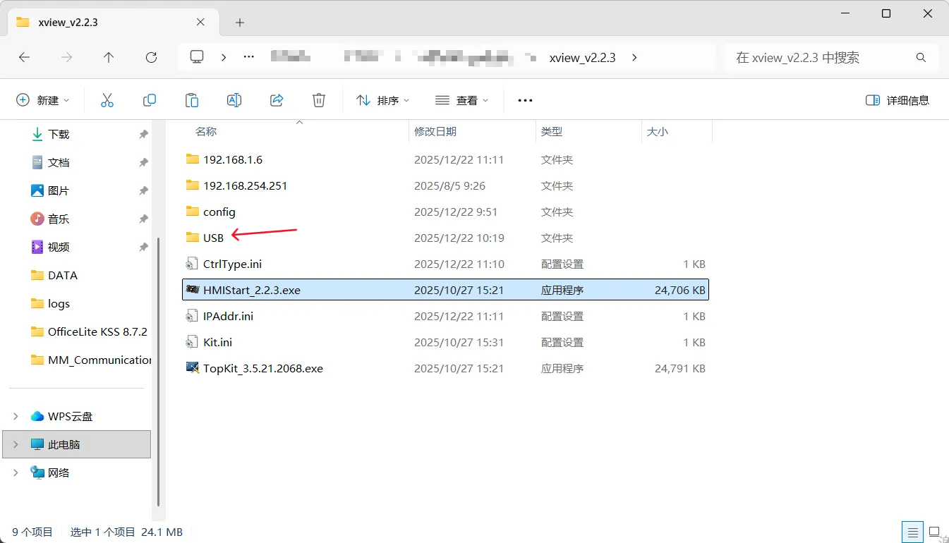
Prepare a blank USB flash drive, create a new folder named USB in the root directory, and then insert it into the USB port on the control cabinet.
Only a folder named USB can be recognized; do not use any other naming convention.
-
Select and switch to Manual Mode on the left menu of the teach pendant.
-
Select the programs to be backed up, then click the Export button at the bottom.
-
A window will pop up allowing you to edit the name of the exported program; click OK to export the program as a backup.
Set up Robot Communication Configuration
-
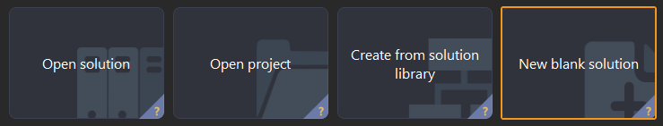
Open Mech-Vision. You may enter different interfaces. Create a new solution according to the instructions below.
-
If you have entered the Welcome interface, click New blank solution.
-
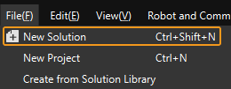
If you have entered the main interface, click on the menu bar.
-
-
Click Robot Communication Configuration on the toolbar of Mech-Vision.
-
In the Robot Communication Configuration window, complete the following configurations.
-
Click the Select robot drop-down menu, and select Listed robot. Click Select robot model, and select the robot model that you use. Then, click Next.
-
It is recommended to set the port number to 50000 or above. Ensure that the port number is not occupied by another program.
-
(Optional) Select Auto enable interface service when opening the solution.
-
Click Apply.
-
-
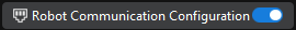
On the main interface of Mech-Vision, make sure that the Robot Communication Configuration switch on the toolbar is flipped and has turned blue.
Prepare Program Files
Software Flashing (PC mode) File Preparation
-
You can also find the program folder in the
Communication Component/Robot_Interface/TOPSTARpath in the installation directory of Mech-Vision and Mech-Viz. -
Copy the following files into the USB folder located in the root directory of the X-View.
-
MM_Auto_Calib.lua
-
MM_COMTEST.lua
-
MM_Module.lua
-
MM_S1_Vis_Basic.lua
-
MM_S2_Viz_Basic.lua
-
MM_S3_Vis_Path.lua
-
Teach Pendant (TP mode) Import File Preparation
-
Prepare a blank USB flash drive (formatting is recommended).
-
You can also find the program folder in the
Communication Component/Robot_Interface/TOPSTARpath in the installation directory of Mech-Vision and Mech-Viz. -
Insert the USB flash drive into the industrial PC and copy the following files to the root directory of the USB drive.
-
MM_Auto_Calib.lua
-
MM_COMTEST.lua
-
MM_Module.lua
-
MM_S1_Vis_Basic.lua
-
MM_S2_Viz_Basic.lua
-
MM_S3_Vis_Path.lua
-
-
Then, unplug the flash drive.
Load the Program Files to the Robot
Flashing can be performed in two ways: software flashing and import via the teach pendant, corresponding to the controller cabinet’s supported PC mode and TP mode.

|
Software Flashing (PC) Steps
-
Turn the control cabinet selector switch to PC Mode.
-
Confirm that the flashing program already exists in the USB folder under the software root directory.
-
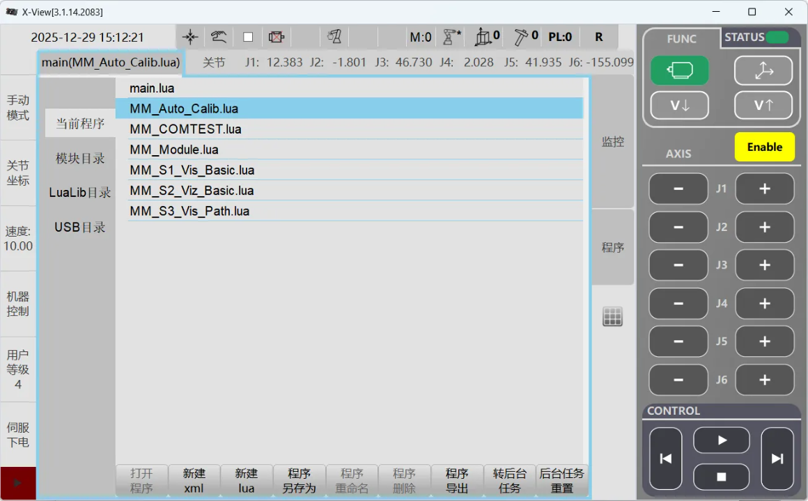
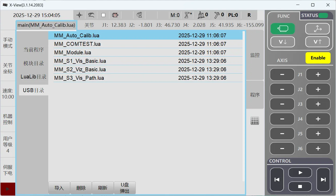
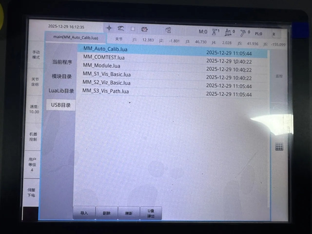
Launch the X-View and go to the USB directory page, where you can browse all programs in the USB folder.
-
Click the main tab to open the Comm. edit page. If a prompt appears in the lower-left corner of the page: “In Remote mode, program list operations are disabled!” Please turn off Remote mode before proceeding with the steps.
-
To switch Remote mode, click the Hand icon in the top menu bar of the software interface. In the pop-up window, click Remote Mode to complete the switch.
-
Click main again to enter the interface, then click USB directory.
-
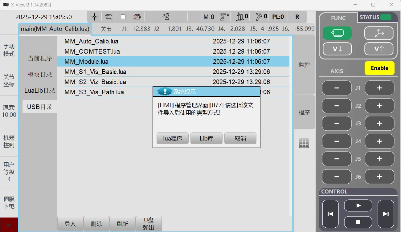
Select each flashing program in turn, click Import, then in the pop-up window click Lua Program to import.
Note: When importing the MM_Module.lua program, select the Library.
Teach Pendant Import (TP) Steps
-
Turn the control cabinet selector switch to TP Mode.
-
Log in to the teach pendant; the user password is 0920.
If a System Warning pop-up appears, click OK.
-
Insert the USB flash drive into the teach pendant.
-
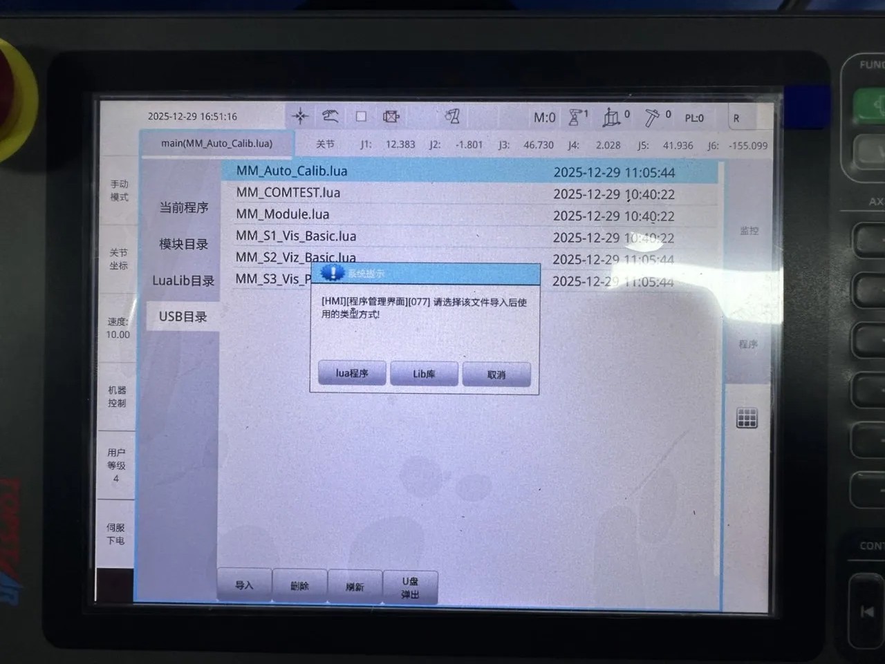
Enter the main interface and click USB directory.
-
Select each flashing program in turn, click Import, then in the pop-up window click Lua Program to import.
Note: When importing the MM_Module.lua program, select the Library.
Test Standard Interface Communication
-
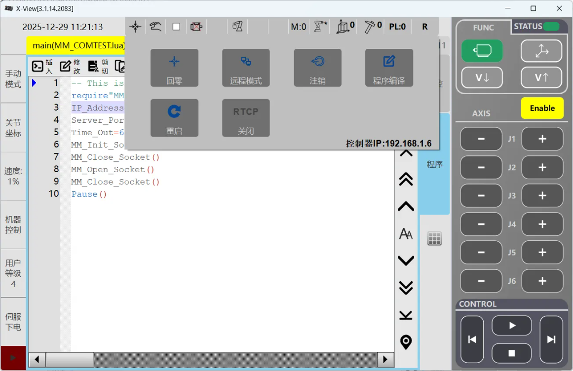
In the X-View software interface, click main and select MM_COMTEST.lua from the program list.
-
Enter the MM_COMTEST.lua program page and modify the IP address and port number. Then, in the software interface, click the robot icon in the upper-right corner and, from the Trigger menu, click Compile.
-
Switch to Debug Mode, then click MM_COMTEST.lua again to open the edit page.
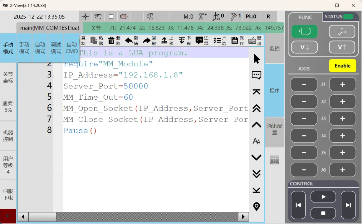
-
Place the cursor on the first line of the program page, then click the Run button in the CONTROL area at the bottom-right
 of the software interface; the robot will start executing the program.
 -
When the connection is successful, Mech-Visionthe returned status information is as shown in the figure below:
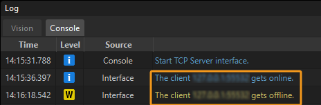
|
The connection test is for testing purposes only; once successfully established, the connection will automatically disconnect. You can view the Client connected and Client disconnected logs on the Console tab of the Mech-Vision Log window. |