Set up Standard Interface Communication with MELFA
This guide shows how to load the Standard Interface program files to a FANUC robot, and set up the Standard Interface communication between Mech-Mind Vision System and the robot.
| In this section, you will load the robot Standard Interface program and the configuration files to the robot system to establish the Standard Interface communication between the vision system and the robot. |
Preparation
Check Controller and Software Compatibility
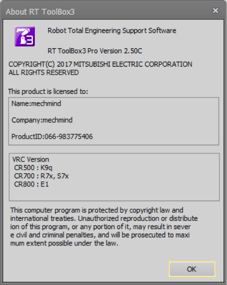
Software Version: RT ToolBox3 Pro Version 2.50C
Controller Version:
-
CR500:K9q
-
CR700:R7x,S7x
-
CR800:E1
Procedure for checking version information:
-
Launch the RT ToolBox3 software (abbreviated “ToolBox3”).
-
Click the Help menu and select Version Information.
Set up the Network Connection
Set the IP Address
The workflow for establishing a network connection via ToolBox3 is as follows:
-
Check robot IP address
-
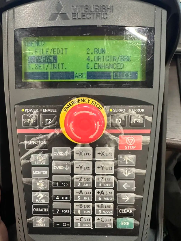
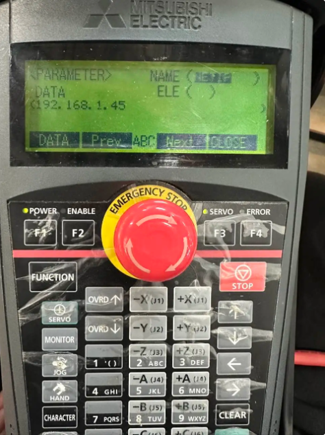
On the teach pendant’s main menu, find PARAM and press EXE.
-
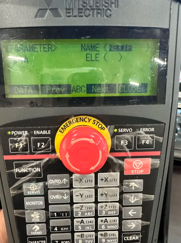
Go to the PARAM page on the teach pendant, enter NETIP in the NAME field, then press EXE to confirm.
-
As shown in the figure, the DATA area displays the robot’s IP address.
-
|
-
Create a robot project in ToolBox3:
-
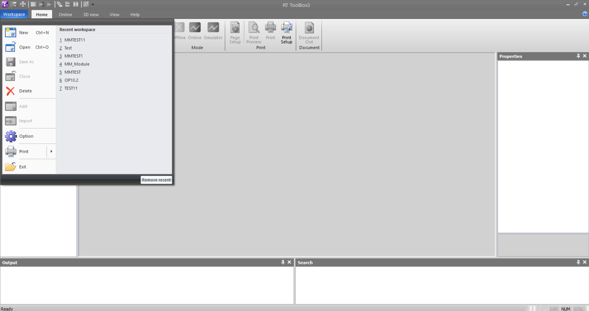
Start ToolBox3, click Workspace to open the main menu, then click New.
-
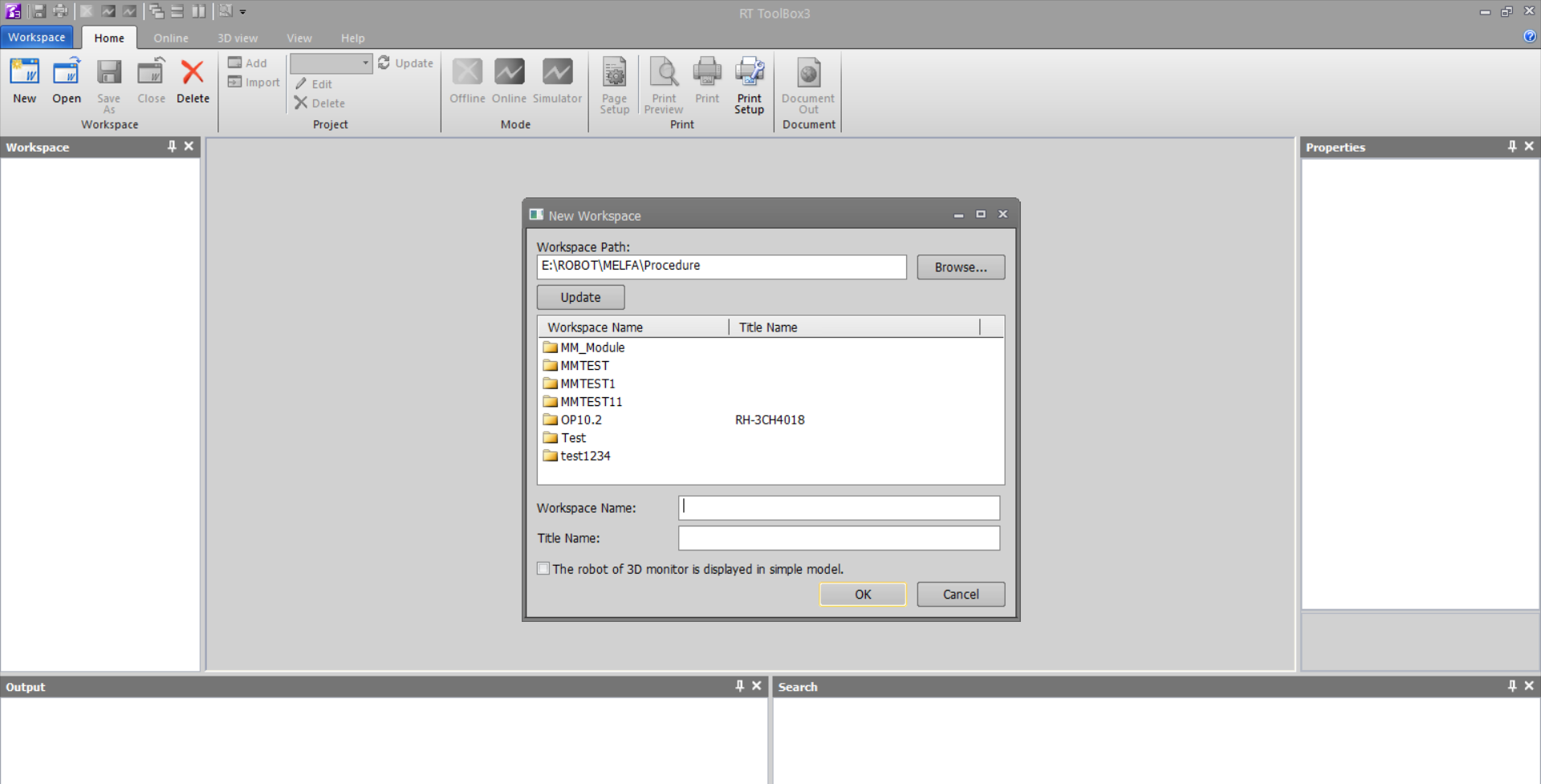
In the pop-up window, select the path for the new workspace, edit the workspace name, then click OK to confirm and complete creation.
-
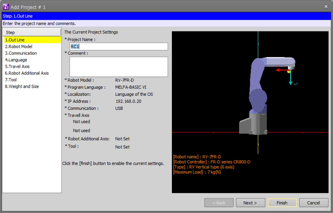
After creating the workspace, the Add Project window opens to the Overview step. Enter the project name and click Next.
-
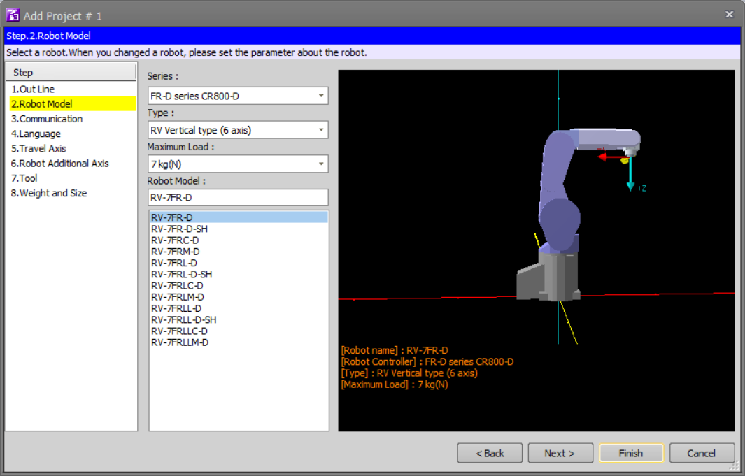
In the Robot Model step, fill in the options based on the actual robot in use, then click Next.
-
In the Communication step, modify the IP address (as viewed on the teach pendant) and the TCP server port number, then click Next.

-
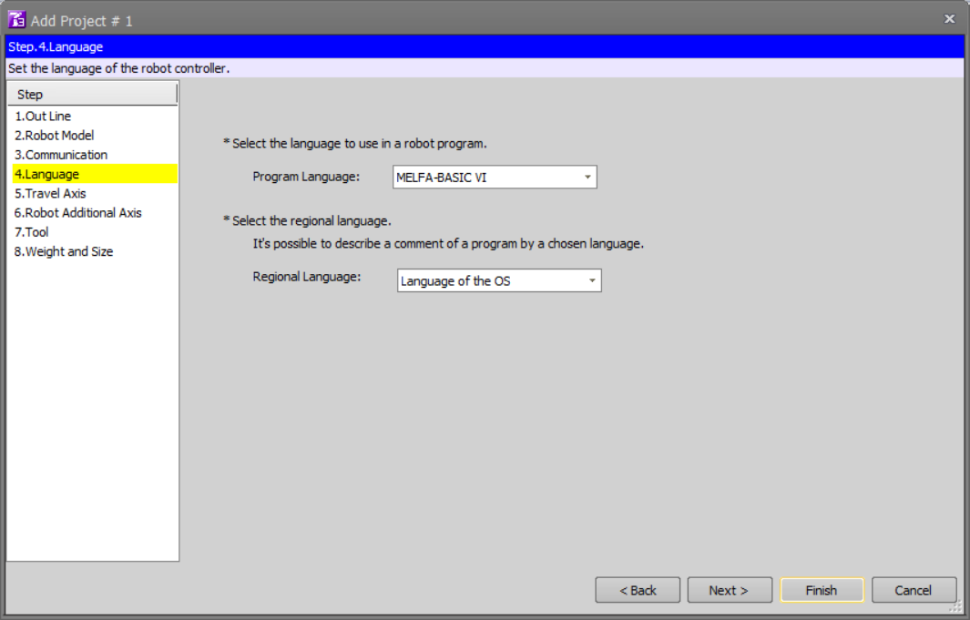
In the Language step, select Robot Language and Regional Language 2 according to the project requirements, then click Finish to create the project.
-
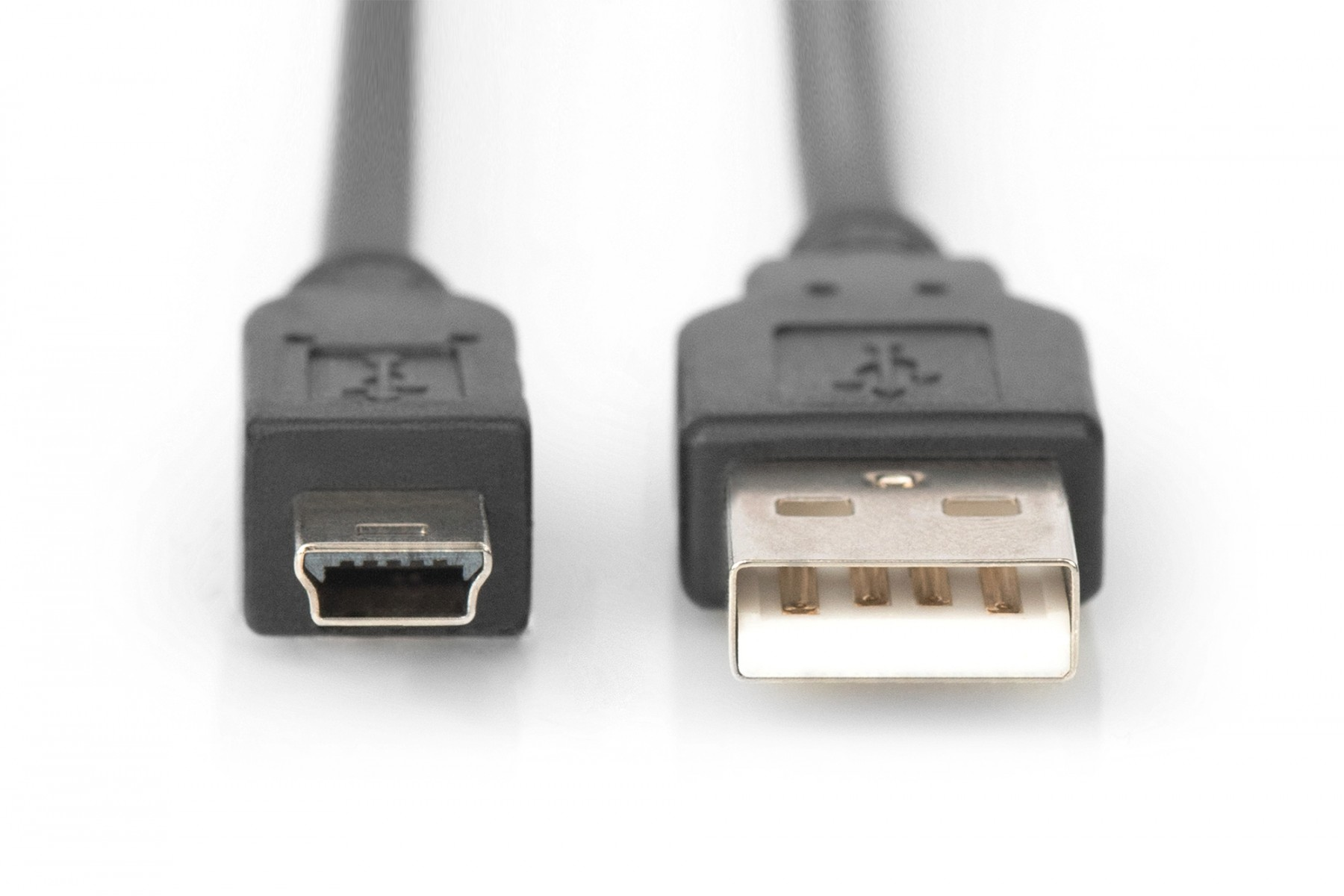
Connect the Hardware
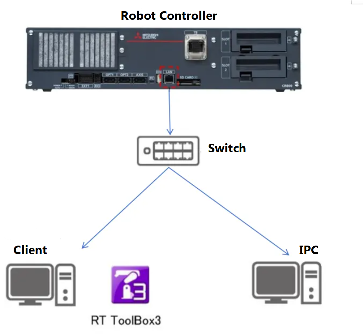
Use an Ethernet cable to connect the robot controller’s LAN port to a switch port. The operating system running the robot software and the operating system running the vision software must both be connected via Ethernet to the same switch, as shown in the figure below.
Controller Communication Connection
-
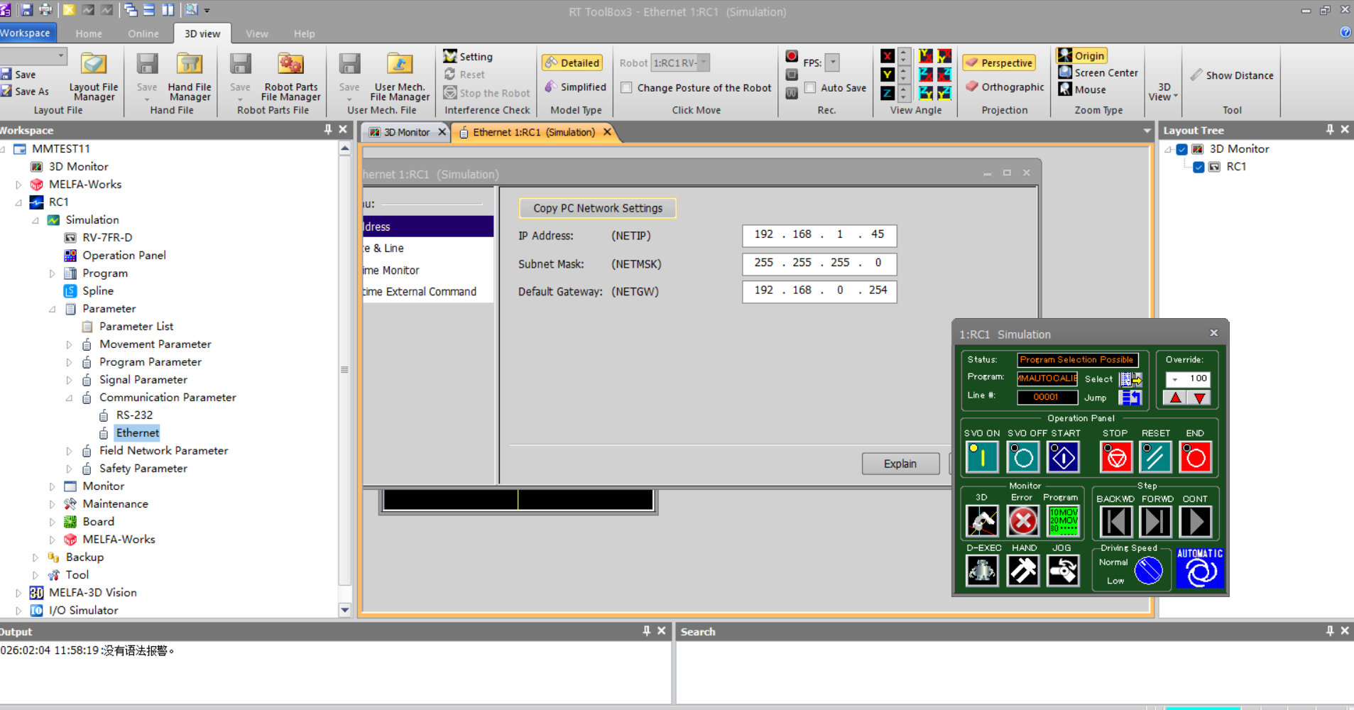
In Workspace/Online/Parameters/Communication Parameters, find and click Ethernet to open it; in the settings page menu, select Device–Port to enter the Device list.
-
Select the OPT device to be used as the communication device, then click the Settings button to open the Device Parameter Settings window. Configure the current device parameters according to the following rules:
-
Mode: Client
-
IP Address: IP address of the IPC
-
Port #: Must match the vision-side port number
-
Protocol: Data Connection
-
Packet Type: 0: CR
-
Allocation: COM7
Within the Allocation options, only COM7 supports controller-to-robot connections. 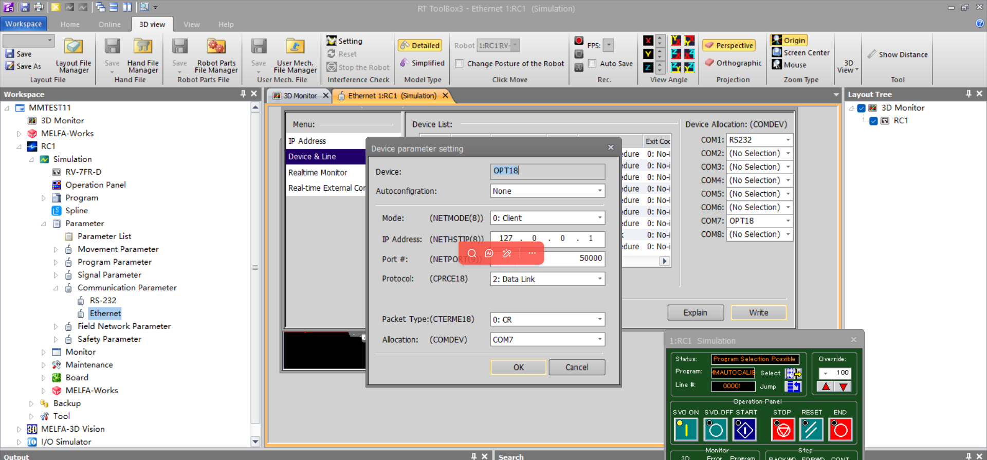
-
Back up Robot Program Files
-
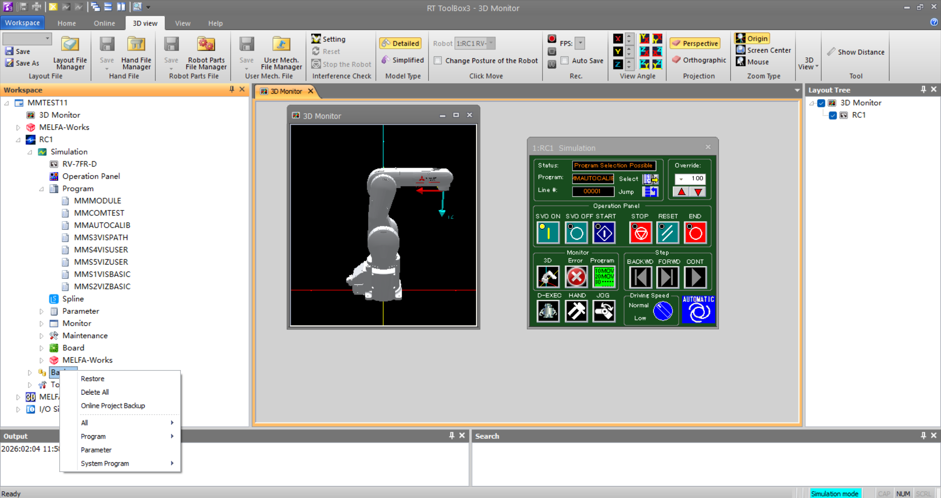
In the ToolBox3 interface, on the left, navigate to Workspace/Project Name/Robot Name/Backup, right-click the Backup folder and click Online Project Backup.
-
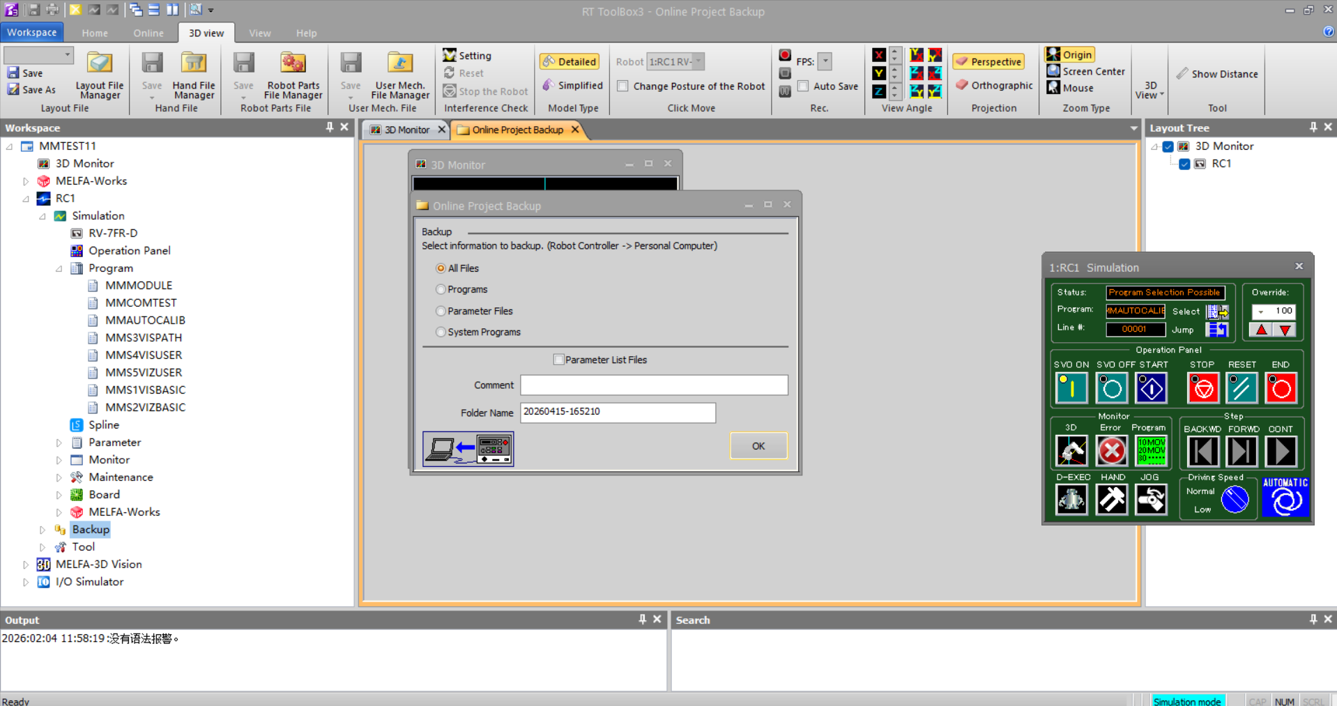
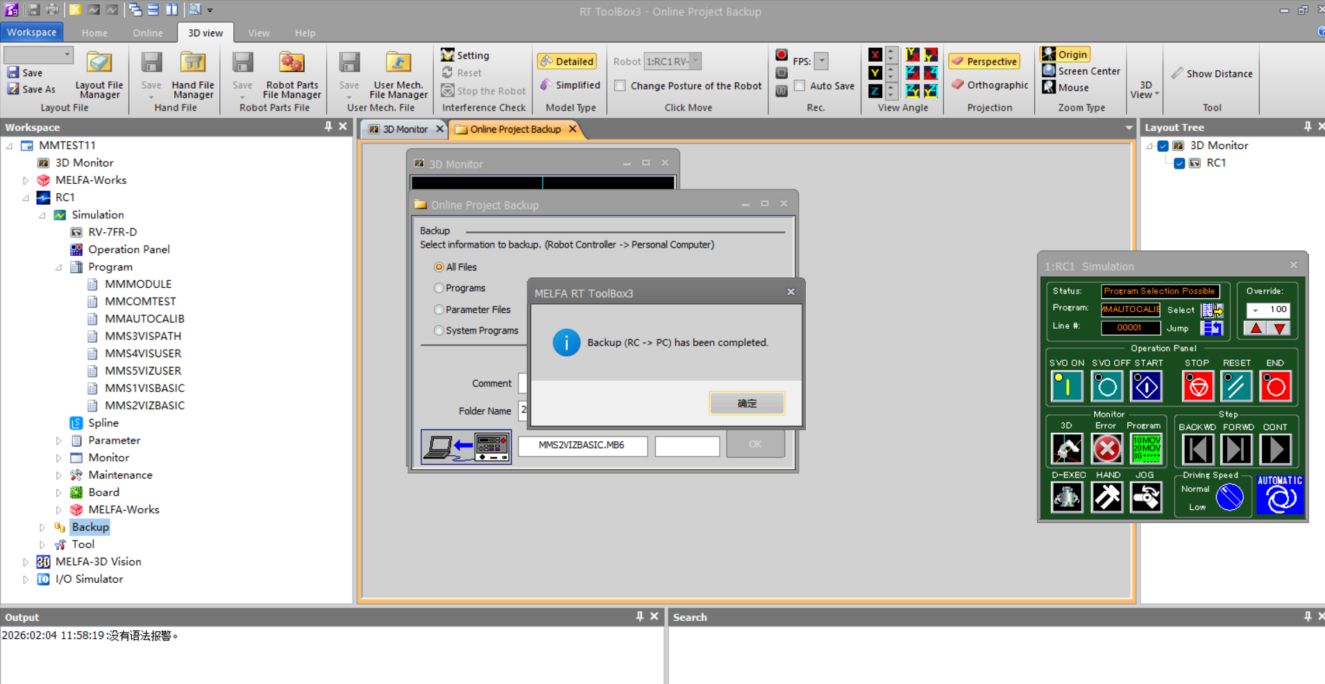
On the Online Project Backup page, confirm Backup is set to All Files, add a Comment and modify the Folder Name (if needed), then click OK.
-
A backup completion message pops up in ToolBox3, indicating the backup was successful.
-
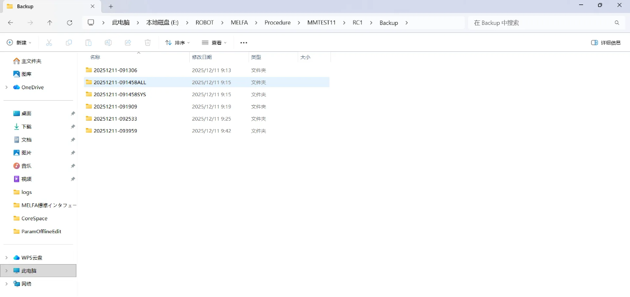
Saved backup files can be found in the project’s Backup folder. If you do not edit the backup Folder Name, the default folder will be named with the operation date and time.
Set up Robot Communication Configuration
-
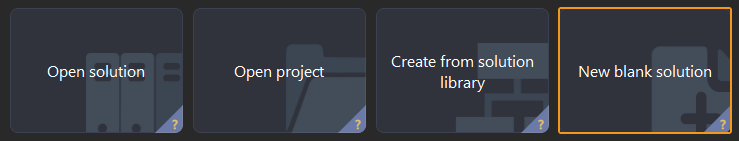
Open Mech-Vision. You may enter different interfaces. Create a new solution according to the instructions below.
-
If you have entered the Welcome interface, click New blank solution.
-
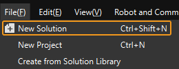
If you have entered the main interface, click on the menu bar.
-
-
Click Robot Communication Configuration on the toolbar of Mech-Vision.
-
In the Robot Communication Configuration window, complete the following configurations.
-
Click the Select robot drop-down menu, and select Listed robot. Click Select robot model, and select the robot model that you use. Then, click Next.
-
It is recommended to set the port number to 50000 or above. Ensure that the port number is not occupied by another program.
-
(Optional) Select Auto enable interface service when opening the solution.
-
Click Apply.
-
-
On the main interface of Mech-Vision, make sure that the Robot Communication Configuration switch on the toolbar is flipped and has turned blue.

Prepare Program Files
-
You can also find the program folder in the
Communication Component/Robot_Interface/MELFApath in the installation directory of Mech-Vision and Mech-Viz. -
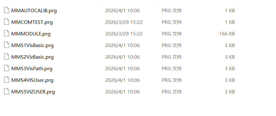
Copy the following files to any folder; the figure below uses Desktop/MELFA as an example.
-
MMAUTOCALIB.prg
-
MMCOMTEST.prg
-
MMMODULE.prg
-
MMS1VisBasic.prg
-
MMS2VizBasic.prg
-
MMS3VisBasic.prg
-
MMS4VISUser.prg
-
MMS5VIZUSER.prg
-
Load the Program Files to the Robot
-
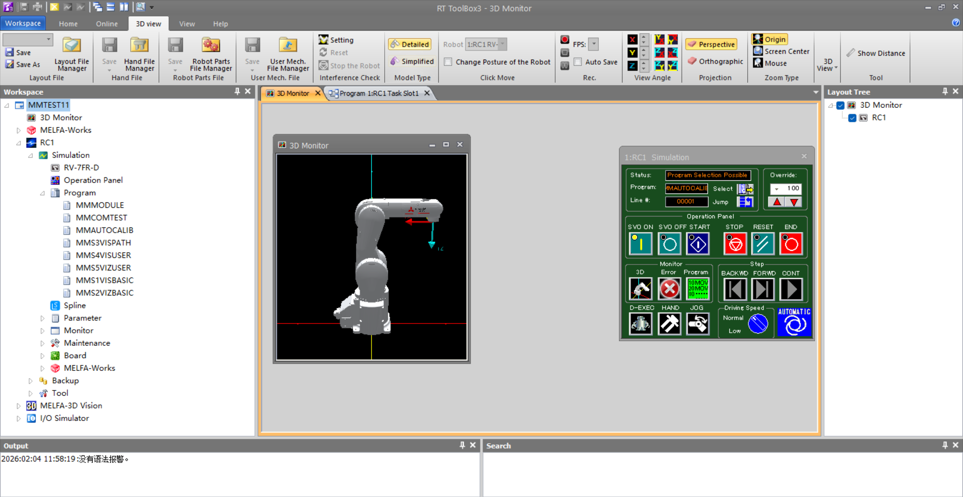
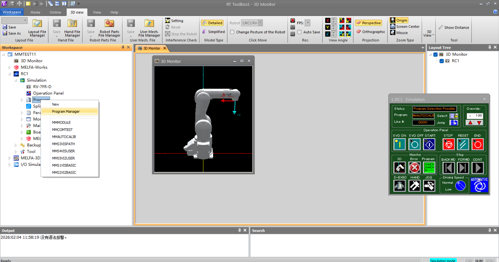
Start ToolBox3, in the left pane navigate to Workspace/Project Name/Robot Name/Simulation, find the Program option, right-click to open the menu, and select Program Manager to open it.
-
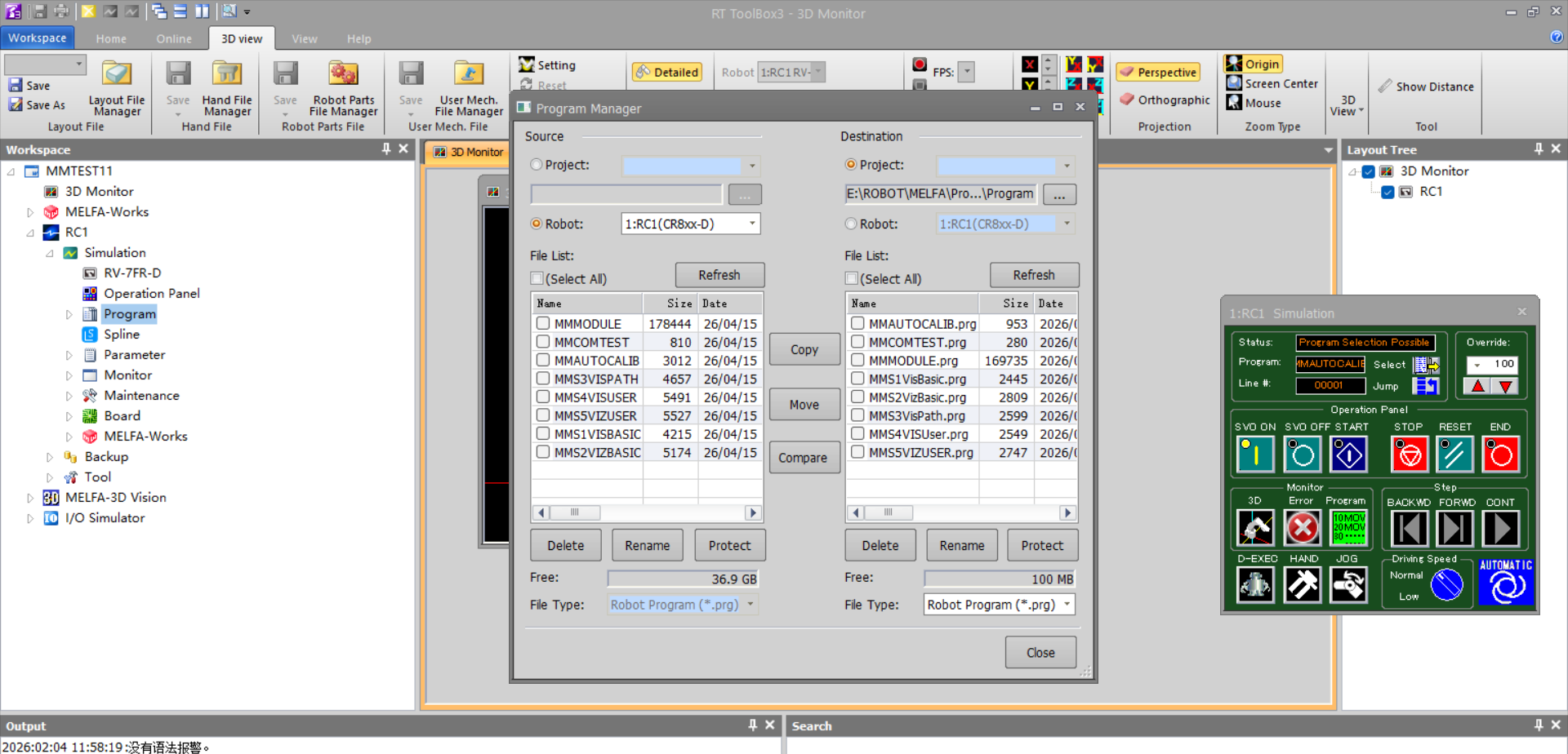
On the Program Manager, in the Source area select Project, click ... to choose the path where the flash files are stored, and confirm the file list in the File List area.
-
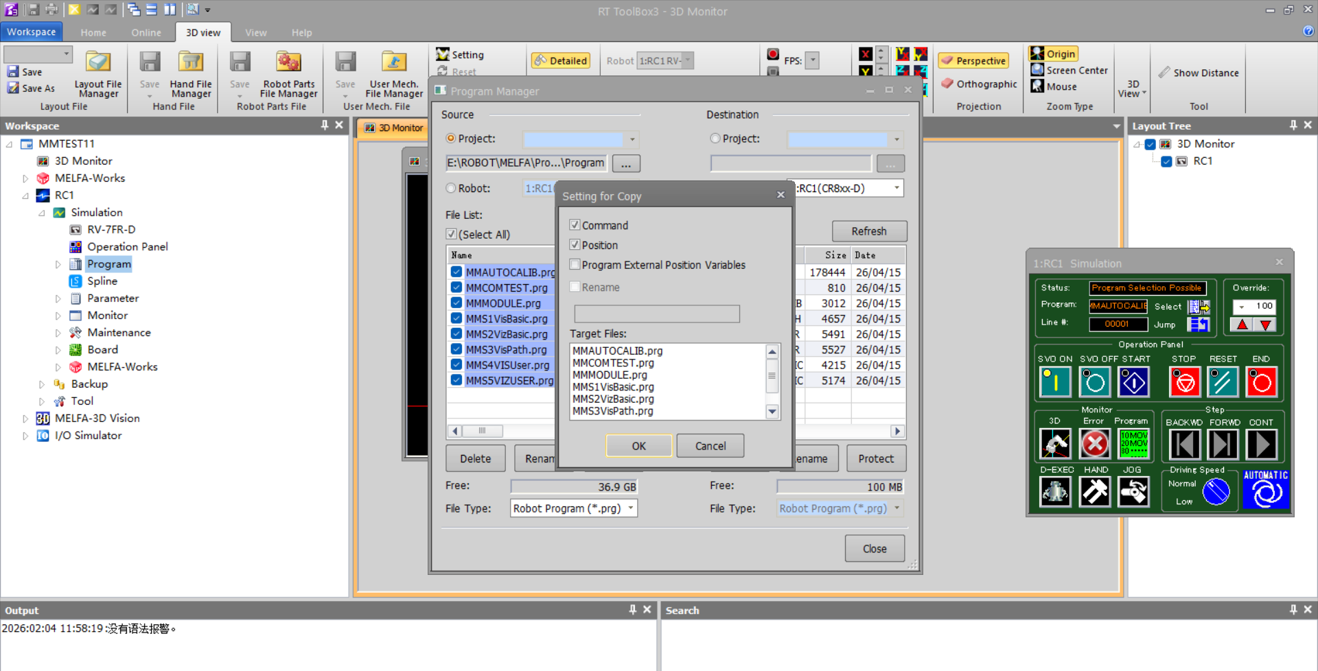
After confirming, check (Select All) to select all flash files in the list, click Copy in the middle of the interface to open the pop-up, verify the copy targets again, then click OK to complete flashing.
-
Confirm that the flash files have been imported into Workspace/Project Name/Robot Name/Simulation/Program.

Test Standard Interface Communication
-
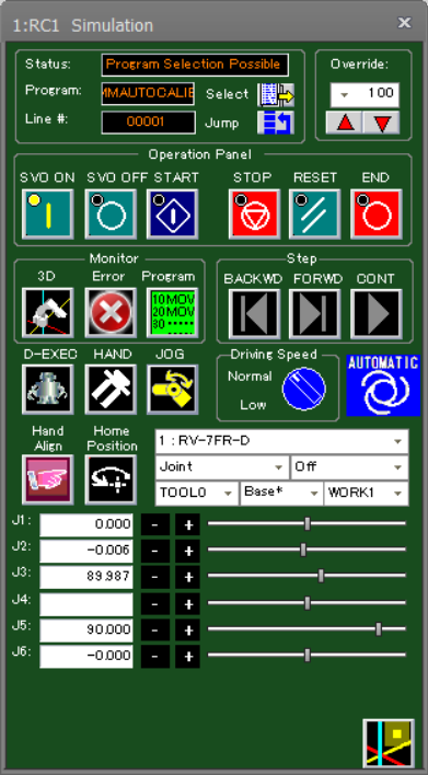
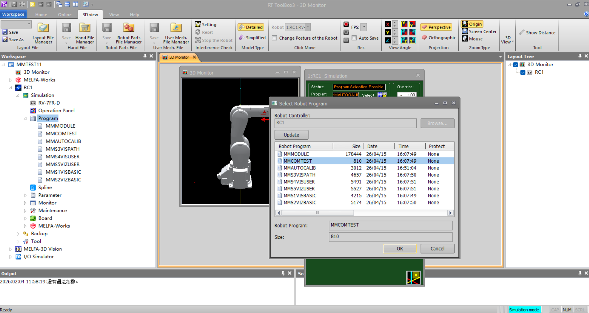
On the robot control panel, click Select to open the ToolBox3 Select Program dialog.
-
In ToolBox3, in the Select Robot Program pop-up, select the MMCOMTEST program and click OK.
-
The test program will run automatically, and Mech-Vision returns the corresponding status information.
-
When the connection is successful, Mech-Visionthe returned status information is as shown in the figure below:
|
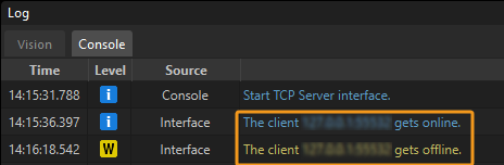
The connection test is for testing purposes only; once successfully established, the connection will automatically disconnect. You can view the Client connected and Client disconnected logs on the Console tab of the Mech-Vision Log window. |