LNX-7500 Series
Sensor Head
Specifications
Model |
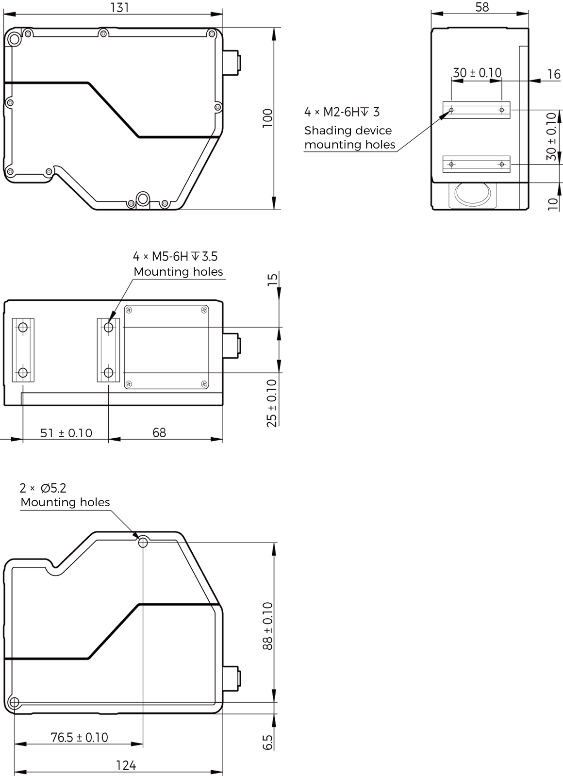
LNX-7515-GL |
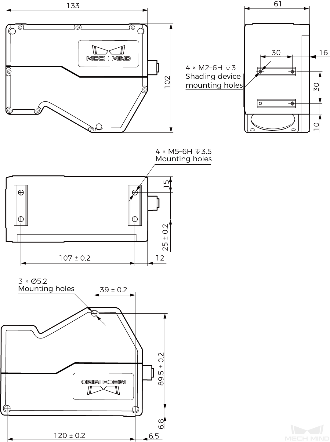
LNX-7530-GL |
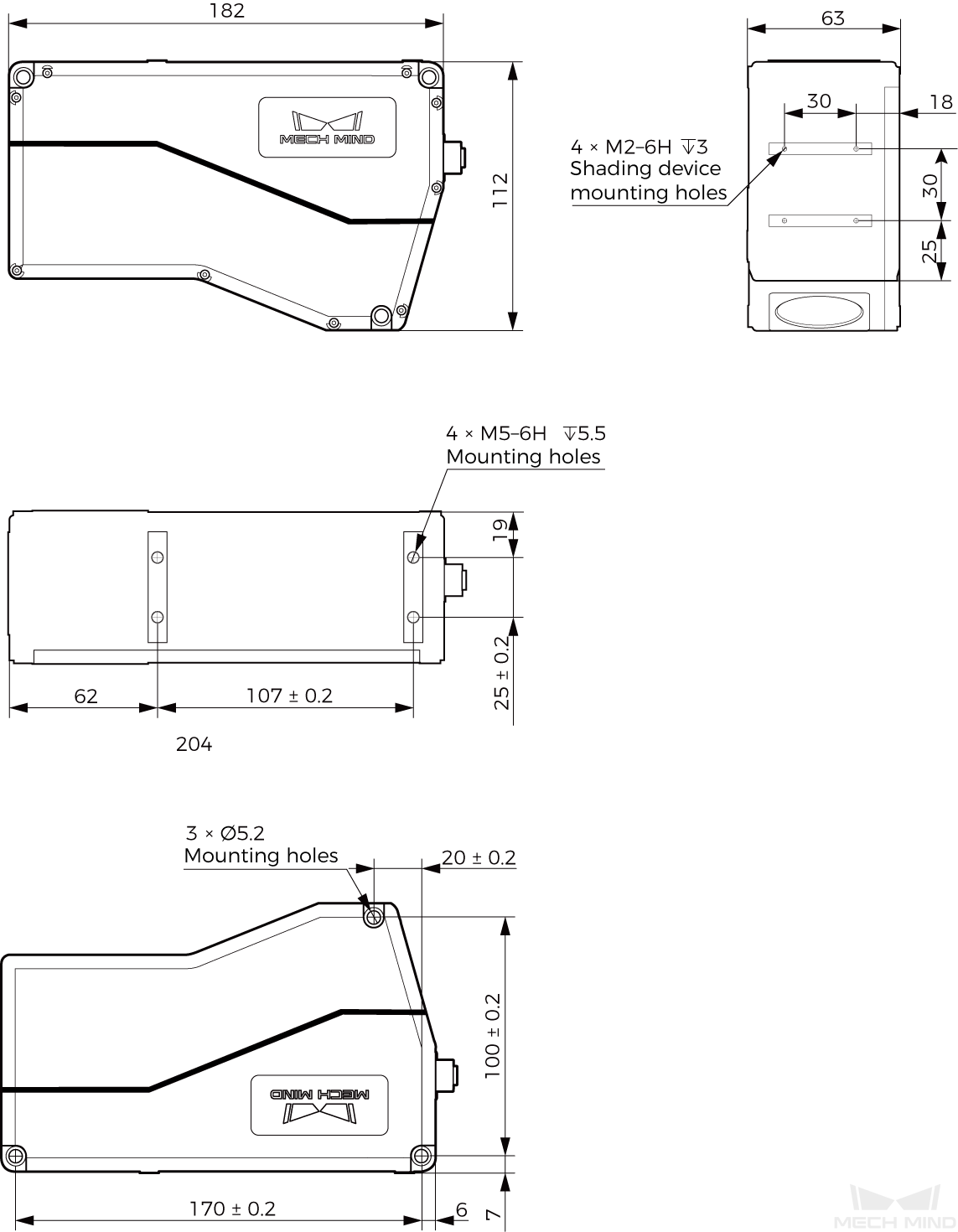
LNX-7580-GL |
||||||||
|---|---|---|---|---|---|---|---|---|---|---|---|
Data points per profile |
3200 |
||||||||||
Scan rate(1) |
4.4–13.8 kHz |
2-10 kHz |
|||||||||
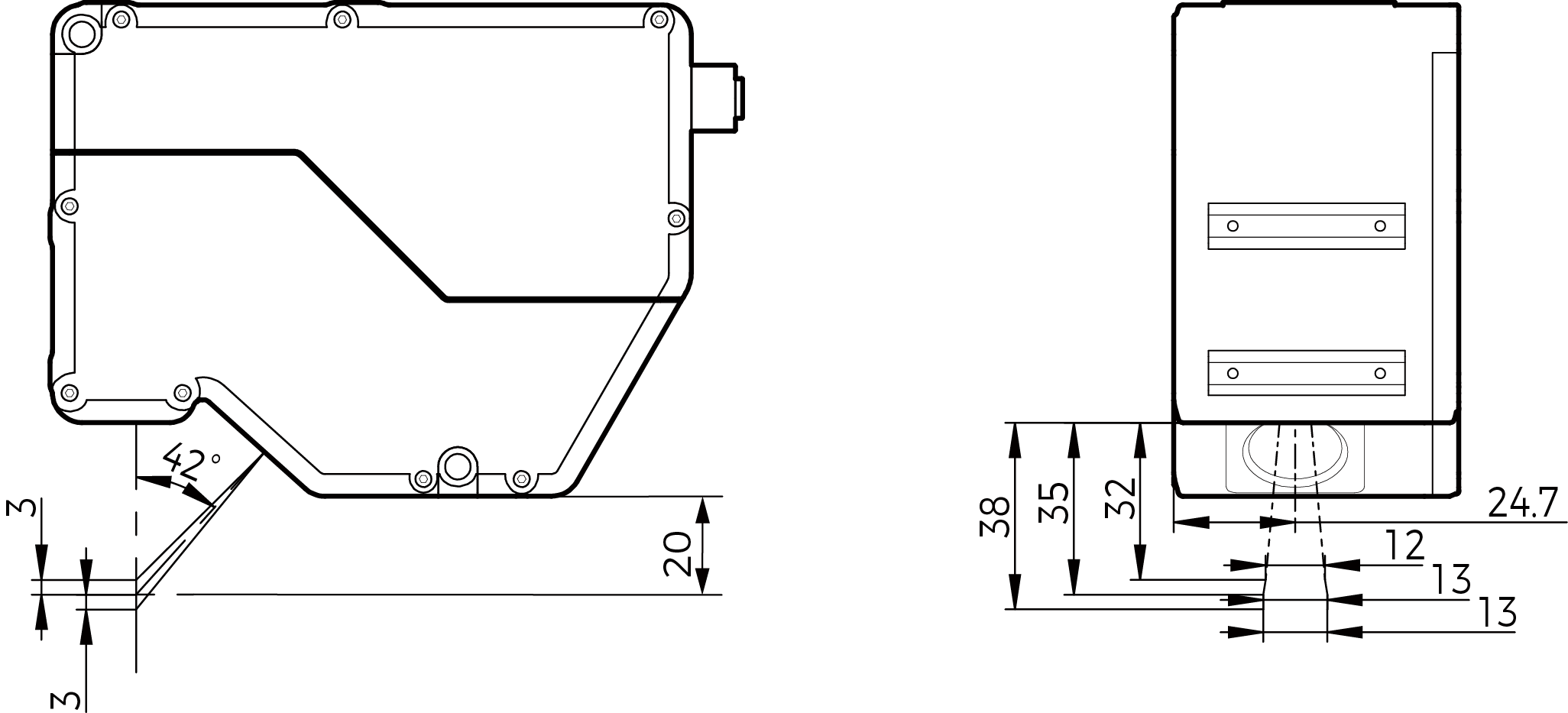
Reference distance (RD) |
35 mm |
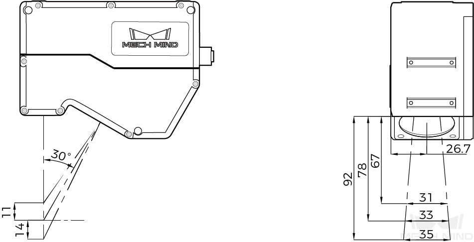
78 mm |
250 mm |
||||||||
Measurement range |
Z-axis |
6 mm |
25 mm |
76 mm |
|||||||
X-axis |
Near |
12 mm |
31 mm |
72 mm |
|||||||
RD |
13 mm |
33 mm |
82 mm |
||||||||
Far |
13 mm |
35 mm |
89 mm |
||||||||
X-axis resolution |
4 μm |
11 μm |
28 μm |
||||||||
Z-axis repeatability |
0.15 μm |
0.2 μm |
0.5 μm |
||||||||
Z-axis linearity |
± 0.02% of F.S. |
||||||||||
Weight |
1.0 kg |
1.0 kg |
1.2 kg |
||||||||
Dimensions |
131 × 58 × 100 mm |
133 × 61 × 102 mm |
182 × 63 × 112 mm |
||||||||
Light source |
Blue laser (405 nm) |
||||||||||
Laser class |
Class 2 |
Class 2M |
|||||||||
Lens inclination(2) |
42° |
30° |
22° |
||||||||
Operating temperature(3) |
0–45 °C |
||||||||||
IP rating(4) |
IP67 |
||||||||||
Cooling |
Passive |
||||||||||
(1) When the Z-Axis Height for the ROI parameter is set to the largest value, the maximum scan rate is 4.4 kHz for LNX-7515-GL and 2 kHz for other models. When the Z-Axis Height is set to the smallest value, the maximum scan rate is 13.8 kHz for LNX-7515-GL and 10 kHz for other models.
(2) Please refer to the diagrams in Field of View.
(3) This is the range when the sensor head is mounted on a metal frame and the heat from the sensor head is well dissipated.
(4) Test implemented based on IEC 60529. 6: dust-tight; 7: protected against the effects of temporary immersion in water.
Model |
LNX-75150-GL |
LNX-75300-GL |
||||||
|---|---|---|---|---|---|---|---|---|
Data points per profile |
3200 |
|||||||
Scan rate(1) |
2-10 kHz |
|||||||
RD |
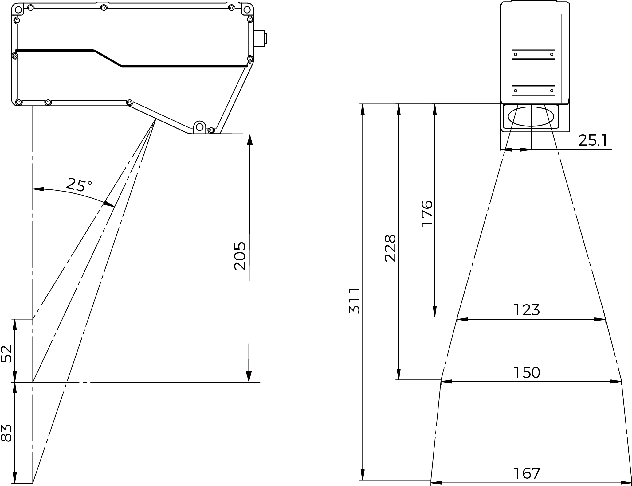
228 mm |
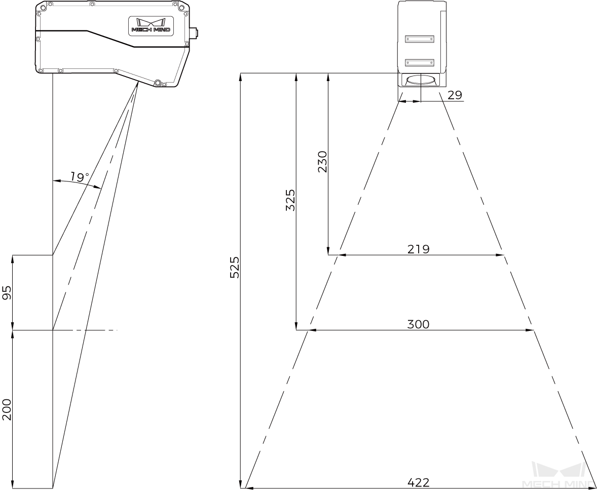
325 mm |
||||||
Measurement range |
Z-axis |
135 mm |
295 mm |
|||||
X-axis |
Near |
123 mm |
219 mm |
|||||
RD |
150 mm |
300 mm |
||||||
Far |
167 mm |
422 mm |
||||||
X-axis resolution |
52 μm |
132 μm |
||||||
Z-axis repeatability |
1.5 μm |
2 μm |
||||||
Z-axis linearity |
± 0.02% of F.S. |
|||||||
Weight |
1.1 kg |
1.4 kg |
||||||
Dimensions |
199 × 57 × 108 mm |
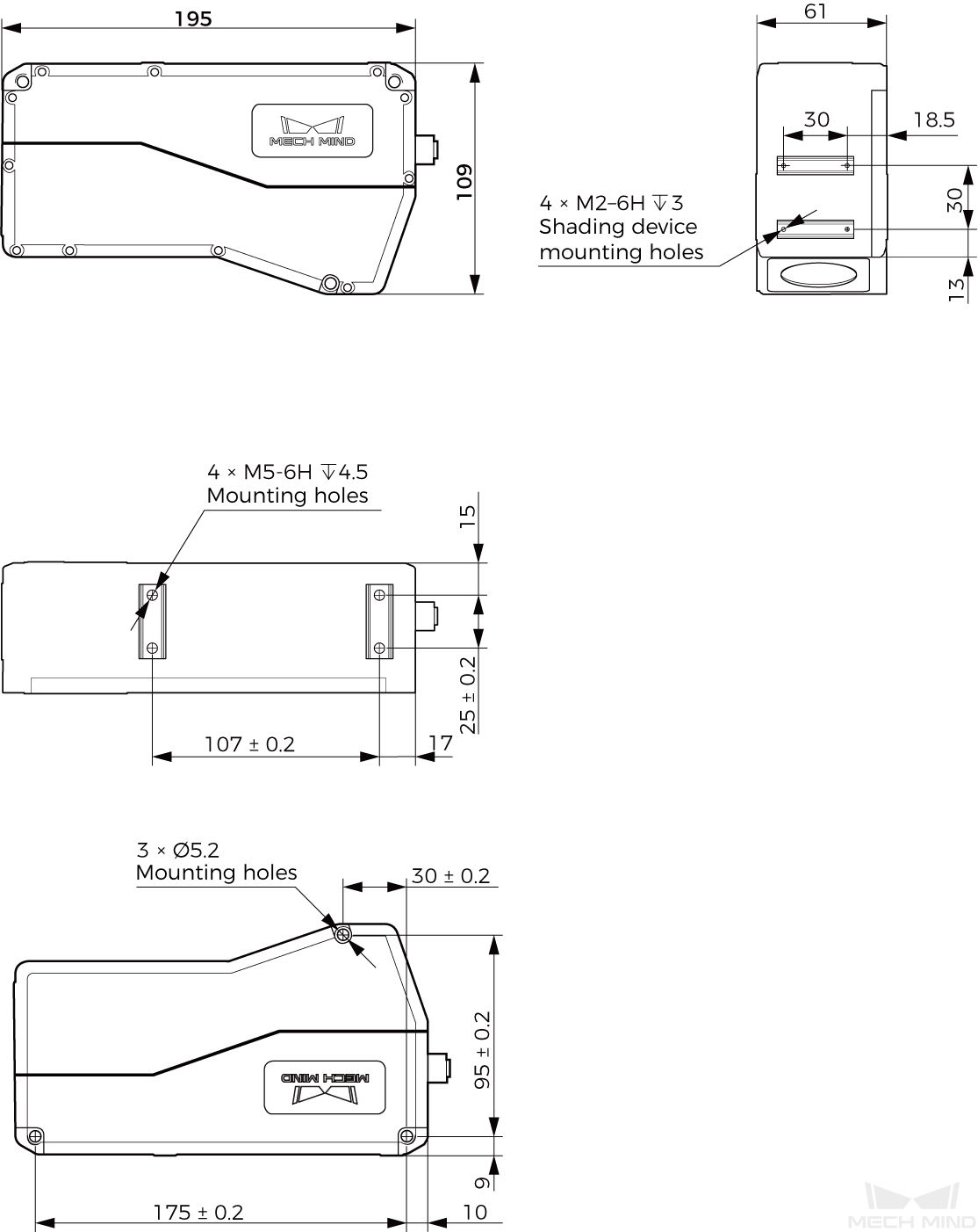
195 × 61 × 109 mm |
||||||
Light source |
Blue laser (405 nm) |
|||||||
Laser class |
Class 2M |
|||||||
Lens inclination(2) |
25° |
19° |
||||||
Operating temperature(3) |
0–45 °C |
|||||||
IP rating(4) |
IP67 |
|||||||
Cooling |
Passive |
|||||||
(1) The maximum scan rate is 2 kHz when the Z-Axis Height for the ROI is set to the largest value and 10 kHz when the Z-Axis Height is set to the smallest value.
(2) Please refer to the diagrams in Field of View.
(3) This is the range when the sensor head is mounted on a metal frame and the heat from the sensor head is well dissipated.
(4) Test implemented based on IEC 60529. 6: dust-tight; 7: protected against the effects of temporary immersion in water.


Controller Port
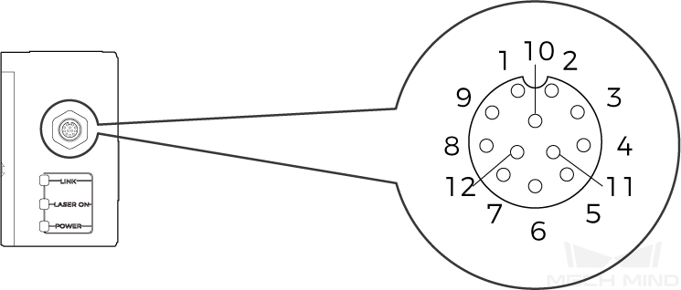
| No. | Name | Function | Description |
|---|---|---|---|
1 |
GigE_MX1+ |
Ethernet signal line |
2.5GigE |
2 |
GigE_MX1- |
Ethernet signal line |
2.5GigE |
3 |
GigE_MX2+ |
Ethernet signal line |
2.5GigE |
4 |
GigE_MX2- |
Ethernet signal line |
2.5GigE |
5 |
GigE_MX3+ |
Ethernet signal line |
2.5GigE |
6 |
GigE_MX3- |
Ethernet signal line |
2.5GigE |
7 |
GigE_MX4+ |
Ethernet signal line |
2.5GigE |
8 |
GigE_MX4- |
Ethernet signal line |
2.5GigE |
9 |
DC_12V |
12 V power supply |
Peak current: 2 A |
10 |
DC_0V |
12 V power supply return line |
Peak current: 2 A |
11 |
Trigger |
Trigger signal input |
Low speed |
12 |
DIR |
Direction signal input |
Low speed |
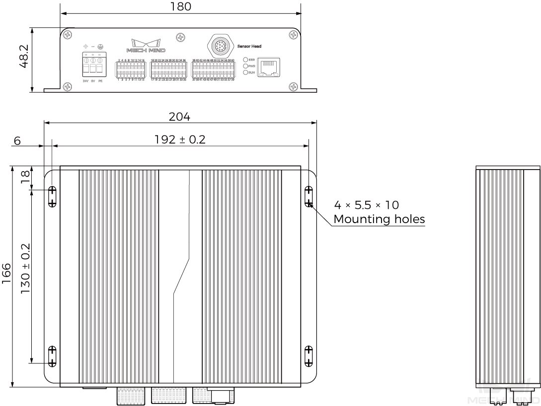
Controller
Specifications
| Model | LNX-7500C-GL |
|---|---|
Weight |
1.2 kg |
Dimensions |
204 × 48.2 × 166 mm |
Input voltage |
24 VDC ± 10% |
Rated current |
2 A |
Peak power |
48 W |
Communication interface |
Gigabit Ethernet |
Encoder Input |
Single-ended and differential encoders supported |
Operating temperature |
0–45°C |
Storage temperature |
-30–70°C |
Safety and EMC |
CE/FCC/VCCI/KC/ISED/NRTL |
Cooling |
Passive |
Sensor Head Port

| No. | Name | Function | Description |
|---|---|---|---|
1 |
GigE_MX1+ |
Ethernet signal line |
2.5GigE |
2 |
GigE_MX1- |
Ethernet signal line |
2.5GigE |
3 |
GigE_MX2+ |
Ethernet signal line |
2.5GigE |
4 |
GigE_MX2- |
Ethernet signal line |
2.5GigE |
5 |
GigE_MX3+ |
Ethernet signal line |
2.5GigE |
6 |
GigE_MX3- |
Ethernet signal line |
2.5GigE |
7 |
GigE_MX4+ |
Ethernet signal line |
2.5GigE |
8 |
GigE_MX4- |
Ethernet signal line |
2.5GigE |
9 |
DC_12V |
12 V power supply |
Peak current: 2 A |
10 |
DC_0V |
12 V power supply return line |
Peak current: 2 A |
11 |
Trigger |
Trigger signal output |
Low speed |
12 |
DIR |
Direction signal output |
Low speed |
Input Signal Terminals

| No. | Name | Description |
|---|---|---|
1 |
IN1 |
Universal digital input 1, optocoupler isolation, bidirectional input optocoupler. |
2 |
IN2 |
Universal digital input 2, optocoupler isolation, bidirectional input optocoupler. |
3 |
IN3 |
Universal digital input 3, optocoupler isolation, bidirectional input optocoupler. |
4 |
IN4 |
Universal digital input 4, optocoupler isolation, bidirectional input optocoupler. |
5 |
IN5 |
Universal digital input 5, optocoupler isolation, bidirectional input optocoupler. |
6 |
IN6 |
Universal digital input 6, optocoupler isolation, bidirectional input optocoupler. |
7–8 |
RESERVED |
Reserved terminals. |
9 |
LEVELCONTROL_ENABLE |
LOW level: Only MEASURE_START controls data acquisition; HIGH level: both MEASURE_START and MEASURE_STOP controls data acquisition. Optocoupler isolation, bidirectional input optocoupler. |
10 |
MEASURE_START |
Input signal to start acquisition, optocoupler isolation, bidirectional input optocoupler. |
11 |
MEASURE_STOP |
Input signal to stop acquisition, optocoupler isolation, bidirectional input optocoupler. |
12 |
RESERVED |
Reserved terminals. |
13–16 |
COM_IN |
Common terminals for input signal. |
|
Output Signal Terminals
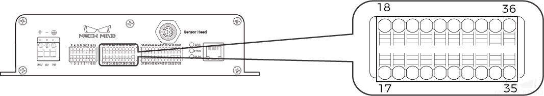
| No. | Name | Description |
|---|---|---|
17–20 |
COM_OUT |
Common terminals for output signal. |
21 |
OUT1 |
Universal digital output 1, optocoupler isolation, NPN output. |
22 |
OUT2 |
Universal digital output 2, optocoupler isolation, NPN output. |
23 |
OUT3 |
Universal digital output 3, optocoupler isolation, NPN output. |
24 |
OUT4 |
Universal digital output 4, optocoupler isolation, NPN output. |
25 |
OUT5 |
Universal digital output 5, optocoupler isolation, NPN output. |
26 |
OUT6 |
Universal digital output 6, optocoupler isolation, NPN output. |
27 |
OUT7 |
Universal digital output 7, optocoupler isolation, NPN output. |
28 |
OUT8 |
Universal digital output 8, optocoupler isolation, NPN output. |
29 |
READY |
Acquisition ready signal, optocoupler isolation, NPN output. |
30 |
ERROR |
Acquisition error signal, optocoupler isolation, NPN output. |
31 |
TRG_ERROR |
Error signal when start signal is received again after acquisition, optocoupler isolation, NPN output. |
32–36 |
RESERVED |
Reserved terminals. |
|
For explanations of the READY, ERROR and TRG_ERROR terminals, please refer to Output Signals to External Device. |
Encoder Signal Terminals
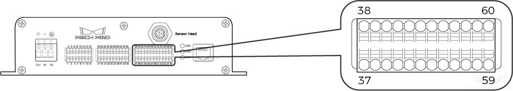
| No. | Name | Description |
|---|---|---|
37 |
A1+ |
Differential encoder A+ input, optocoupler isolation, RS-422 standard differential input. |
38 |
A1- |
Differential encoder A- input, optocoupler isolation, RS-422 standard differential input. |
39 |
B1+ |
Differential encoder B+ input, optocoupler isolation, RS-422 standard differential input. |
40 |
B1- |
Differential encoder B- input, optocoupler isolation, RS-422 standard differential input. |
41 |
Z1+ |
Differential encoder Z+ input, optocoupler isolation, RS-422 standard differential input. |
42 |
Z1- |
Differential encoder Z- input, optocoupler isolation, RS-422 standard differential input. |
43 |
A2+24 |
Single-ended encoder A+ input, 24 V, optocoupler isolation. |
44 |
A2+12 |
Single-ended encoder A+ input, 12 V, optocoupler isolation. |
45 |
A2+5 |
Single-ended encoder A+ input, 5 V, optocoupler isolation. |
46 |
A2- |
Single-ended encoder A- input, common, optocoupler isolation. |
47 |
B2+24 |
Single-ended encoder B+ input, 24 V, optocoupler isolation. |
48 |
B2+12 |
Single-ended encoder B+ input, 12 V, optocoupler isolation. |
49 |
B2+5 |
Single-ended encoder B+ input, 5 V, optocoupler isolation. |
50 |
B2- |
Single-ended encoder B- input, common, optocoupler isolation. |
51 |
Z2+24 |
Single-ended encoder Z+ input, 24 V, optocoupler isolation. |
52 |
Z2+12 |
Single-ended encoder Z+ input, 12 V, optocoupler isolation. |
53 |
Z2+5 |
Single-ended encoder Z+ input, 5 V, optocoupler isolation. |
54 |
Z2- |
Single-ended encoder Z- input, common, optocoupler isolation. |
55 |
R1 |
RS-232 serial interface 1, input, magnetic isolation. |
56 |
T1 |
RS-232 serial interface 1, output, magnetic isolation. |
57 |
G1 |
RS-232 serial interface 1 ground reference. |
58 |
G2 |
RS-232 serial interface 2 ground reference. |
59 |
R2 |
RS-232 serial interface 2, input, magnetic isolation. |
60 |
T2 |
RS-232 serial interface 2, output, magnetic isolation. |

Hereby [Mech-Mind Robotics Technologies Co., Ltd.] declares that [LNX-7530-GL], [LNX-7580-GL], [LNX-75150-GL], [LNX-75300-GL], and [LNX-7500C-GL] are in compliance with the Electromagnetic Compatibility Directive 2014/30/EU.
The full text of the EU Declaration of Conformity is available at https://downloads.mech-mind.com/?tab=tab-eu-dec