Measurement Tool
This tool is used to measure the point-to-point distance, point-to-line distance, and height difference in the profile, in order to check if the target object meets the design accuracy requirements.
Click Tools in the menu bar, and select Measurement Tool to open the Measurement Tool.
Prerequisites
Before you start the measurement, please check the following prerequisites:
-
To ensure the accuracy of the measurement result, please perform tilt correction and height correction before measurement.
-
While conducting the following measurement actions, you should keep the target object still. If you need to measure different locations, click Acquire again after moving the target object to acquire the profile again.
Measurement Mode
This tool provides three measurement modes:
Point-to-point distance |
|
|---|---|
Point-to-line distance |
|
Height difference |
|
In each mode, Measurement Tool detects the measurement target automatically in the selected detection area, and then provides the measurement result.
The following sections provide measurement instructions based on the measurement mode. Please check the corresponding section according to your actual measurement needs.
Measure Point-to-Point Distance
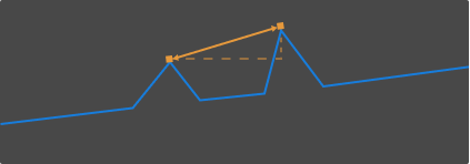
In the point-to-point distance measurement mode, the measurement targets are two automatically detected points, and the measurement result is the distance between the two points.
The detectable types of points include:
Highest point |
|
|---|---|
Lowest point |
|


When measuring, you need to set appropriate positions and widths of the detection areas to ensure that the correct points are detected.
Follow these steps to measure the point-to-point distance:
-
In Measurement Mode, select Point-to-point distance.
-
In the right panel, from the Point type menu under the Measurement target 1 tab, select the type of the first point that needs to be measured.
-
In the image area on the left, select detection area 1 (
 ) and drag to adjust its position, so that it includes the point to be measured.
 -
Select detection area 1 and drag the left or right side to adjust its width, so that its as narrow as possible.
Reducing the width of the detection area can exclude unneeded data and ensure that the automatically detected point is the point that needs to be measured. For example, if the point that needs to be measured should be the highest point in the detection area, the detection area should not include any point higher than that point. -
In the right panel, switch to the Measurement target 2 tab, and from the Point type menu, select the type of the second point that needs to be measured.
-
In the image area on the left, select detection area 2 (
 ) and drag to adjust its position, so that it includes the point to be measured.
The detection areas can overlap. -
Select detection area 2 and drag the left or right side to adjust its width, so that its as narrow as possible.
-
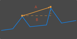
In Measurement method in the right panel, select the method used to measure the point-to-point distance:
-
Straight-line distance: A in the following figure
-
Horizontal distance: B in the following figure
-
-
Check the measurement result of the point-to-point distance in Measurement result at the bottom of the right panel. If the measurement result is inaccurate or not displayed, adjust the positions and widths of the detection areas again.
Measure Point-to-Line Distance
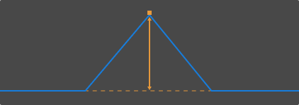
In the point-to-line distance measurement mode, the measurement targets are a automatically detected point and a reference line calculated from the selected data, and the measurement result is the distance between the vertical distance between the point and the reference line.
The detectable types of points include:
Highest point |
|
|---|---|
Lowest point |
|
When measuring, you need to set appropriate positions and widths of the detection areas to ensure that the correct points are detected.
Follow these steps to measure the point-to-line distance:
-
In Measurement Mode, select Point-to-line distance.
-
In the right panel, from the Point type menu under the Measurement target 1 tab, select the type of the point that needs to be measured.
-
In the image area on the left, select detection area 1 (
) and drag to adjust its position, so that it includes the point to be measured. -
Select detection area 1 and drag the left or right side to adjust its width, so that its as narrow as possible.
Reducing the width of the detection area can exclude unneeded data and ensure that the automatically detected point is the point that needs to be measured. For example, if the point that needs to be measured should be the highest point in the detection area, the detection area should not include any point higher than that point. -
In the image area on the left, select detection area 2 (
) and drag to adjust its position, so that it includes the data used for calculating the reference line.The orange line in the image area on the left is the calculated reference line. -
Select detection area 2 and drag the left or right side to adjust its width. Refer to the following criteria while adjusting the width:
-
The profile selected by the detection area should correspond to points on the same plane of the target object.
-
With the above criterion satisfied, the detection area can be as wide as possible to include more data for calculating the reference line.
If the calculating result is not good, you can add detection area 3 to calculate the reference line using the data from both detection areas 2 and 3:
Under the Reference tab in the right panel, check detection area 3, and adjust the position and width of detection area 3 (
 ) in the image area on the left.
-
-
Check the measurement result of the point-to-line distance in Measurement result at the bottom of the right panel. If the measurement result is inaccurate or not displayed, adjust the positions and widths of the detection areas again.
Measure Height Difference
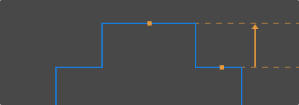
In the height difference measurement mode, the measurement targets are two automatically detected points or lines, and the measurement result is the perpendicular distance between the two measurement targets.
The detectable types of measurement targets include:
Highest point |
|
|---|---|
Lowest point |
|
Average |
|
When measuring, you need to set appropriate positions and widths of the detection areas to ensure that the correct points are detected.
Follow these steps to measure the height difference:
-
In Measurement Mode, select Height difference.
-
In the right panel, from the Measurement target type menu under the Measurement target 1 tab, select the type of the first measurement target.
-
In the image area on the left, select detection area 1 (
) and drag to adjust its position, so that it includes the measurement target. -
Select detection area 1 and drag the left or right side to adjust its width. Refer to the following criteria while adjusting the width:
-
If the measurement target is Highest point or Lowest point:
Reducing the width of the detection area as much as possible to exclude unneeded data and ensure that the automatically detected point is the point that needs to be measured. For example, if the point that needs to be measured should be the highest point in the detection area, the detection area should not include any point higher than that point.
-
If the measurement target is Average:
The detection area should include only the points used to calculate the average. Meanwhile, the detection area should be as wide as possible to include more data for calculating the average.
The orange line in the image area on the left is the line that represents the average.
-
-
In the right panel, from the Measurement target type menu under the Reference tab, select the type of the second measurement target.
-
Refer to steps 3 to 4 and adjust the position and width of detection area 2 (
). -
Check the measurement result of the height difference in Measurement result at the bottom of the right panel. If the measurement result is inaccurate or not displayed, adjust the positions and widths of the detection areas again.