Scan Mode
This topic provides descriptions of the parameters in the scan mode.
1. Trigger Settings
Select the trigger sources and set relevant parameters.
| For the methods of triggering the laser profiler to acquire data in the scan mode, please refer to Methods for Triggering Data Acquisition. |
1.1. Data Acquisition Method
Description |
This parameter, together with the data acquisition buttons, determines how to generate data. |
||
|---|---|---|---|
Visibility |
Beginner, Expert, Guru |
||
Values |
|
||
Instructions |
When each option is selected, the functions of the data acquisition buttons are as follows:
|
1.2. Data Acquisition Trigger Source
Description |
Select the source of the signals that trigger data acquisition. In one round of data acquisition, multiple lines are scanned, multiple profiles are generated, and one intensity image and one depth map are generated using the profile data. |
||
|---|---|---|---|
Visibility |
Beginner, Expert, Guru |
||
Values |
|
||
Instruction |
If you use externally input signals to trigger data acquisition, select External. Otherwise, select Software.
|
1.3. Line Scan Trigger Source
Description |
Select the source of the signals that trigger the scan of a single line. |
||
|---|---|---|---|
Visibility |
Beginner, Expert, Guru |
||
Values |
|
||
Instruction |
After selecting different options, different parameters are displayed in the Trigger Settings category for adjustment:
|
1.4. Encoder: Encoder Settings
When Line Scan Trigger Source is set to Encoder, adjust the parameters in this category.
Click Edit to open the Encoder Settings tool. You can check the encoder value and motion direction, and have the encoder resolution calculated.
If you need the Y-axis resolution of the scan data to be equal to the X-axis resolution, you can also use this tool to get the recommended value of Trigger Interval.
1.4.1. Trigger Direction
Description |
Select the encoder motion direction that triggers scanning. |
||
|---|---|---|---|
Visibility |
Beginner, Expert, Guru |
||
Values |
|
||
Instruction |
Adjust this parameter based on the encoder motion direction and the motion direction of the target object relative to the laser profiler.
|
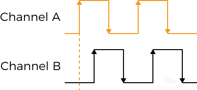
1.4.2. Trigger Signal Counting Mode
Description |
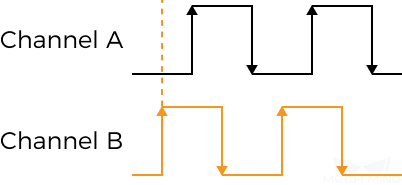
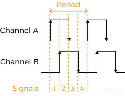
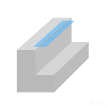
Set the number of quadrature signals to be counted in an encoder period. Counted signals are used to trigger scanning (These signals are trigger signals). Each encoder period contains 4 quadrature signals, as shown below.
|
||
|---|---|---|---|
Visibility |
Beginner, Expert, Guru |
||
Values |
|
||
Instruction |
This parameter and Trigger Interval together determine the rate at which scanning is triggered.
|
1.4.3. Trigger Interval
Description |
Set the number of trigger signals needed for scanning one line. |
||
|---|---|---|---|
Visibility |
Beginner, Expert, Guru |
||
Values |
|
||
Instruction |
This parameter and Trigger Signal Counting Mode together determine the rate at which scanning is triggered.
|
1.5. Fixed-Rate: Trigger Rate
Description |
When Line Scan Trigger Source is set to Fixed rate, set the fixed rate at which the laser profiler is triggered to scan. |
||
|---|---|---|---|
Visibility |
Beginner, Expert, Guru |
||
Values |
|
||
Instruction |
|
1.6. Fixed Rate: Travel Speed
Parameter Description |
When Line Scan Trigger Source is set to Fixed rate, set the travel speed of the target object relative to the laser profiler. |
|---|---|
Visibility |
Beginner, Expert, Guru |
Instruction |
This parameter is used to calculate the Y-axis resolution of the scan data. The calculation method is as follows: Y-Axis Resolution (μm) = Travel Speed (μm/s) ÷ Trigger Rate |
1.7. Trigger Delay
Parameter Description |
Sets the delay time between receiving a line scan trigger signal and emitting laser light. |
|---|---|
Visibility |
Guru |
Values |
|
Instruction |
|
1.7.1. Adjust Trigger Delay
In the following situation, you need to adjust Trigger Delay:
-
Multiple laser profilers are used to scan the same target object.
-
The line scans of all laser profilers are triggered by a single encoder.
-
The FOVs of the laser profilers overlap. The laser profilers will interfere with each other if they emit laser light at the same time.

With an appropriate value of Trigger Delay, laser profilers emit laser light at different times and acquire data without interference.
|
Adjusting the value of Trigger Delay will have the following impacts:
|
Follow the steps below to adjust Trigger Delay:
-
Adjust the parameters of each laser profiler according to Profile Mode and Scan Mode, and ensure that the data acquired with each laser profiler fulfill the requirements.
-
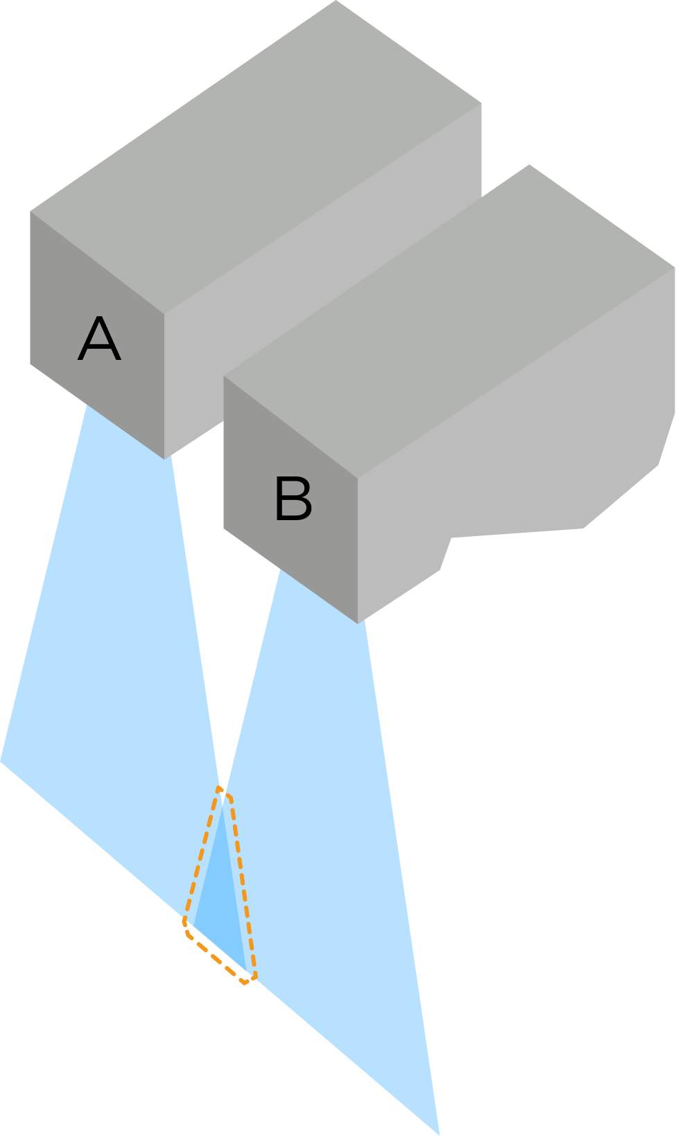
If more than two laser profilers are used, check the overlap of FOVs:
Overlap of FOVs
FOVs of all laser profilers overlap
FOVs of some laser profilers do not overlap (A and C in the image below)
Example of spatial relationship
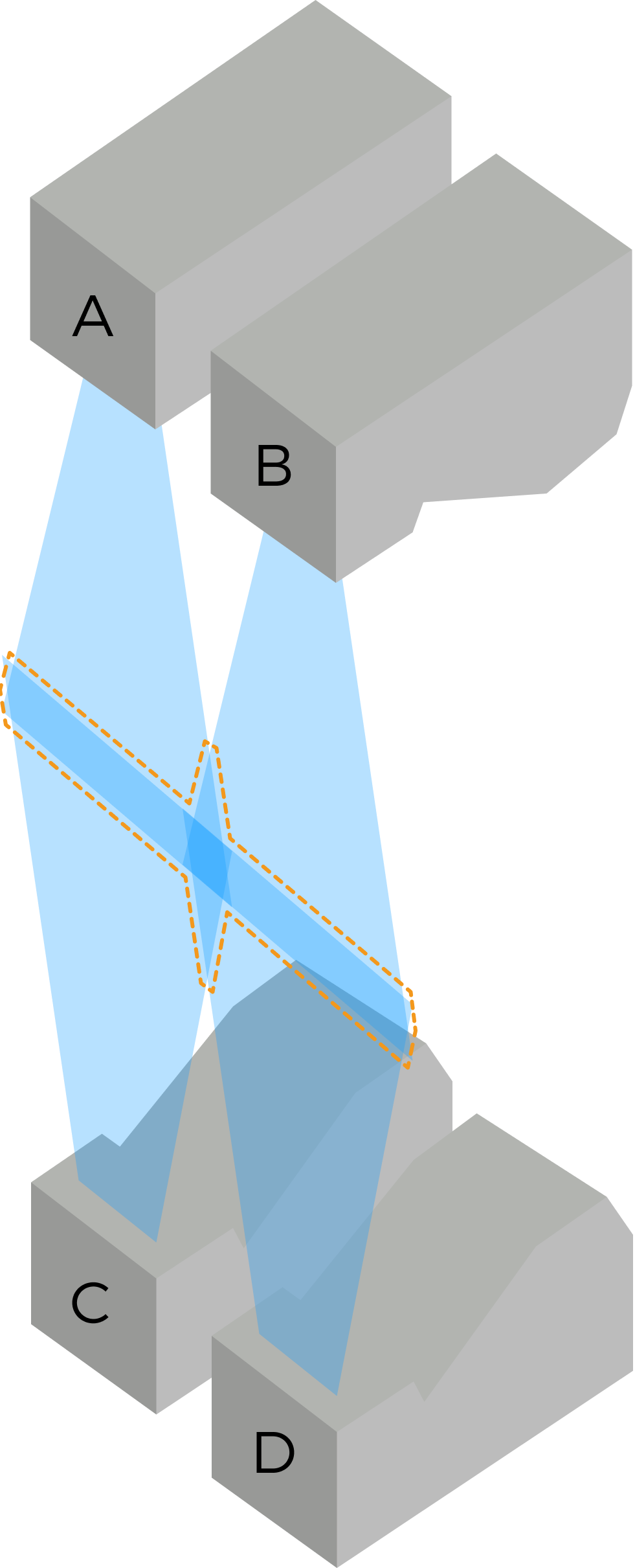
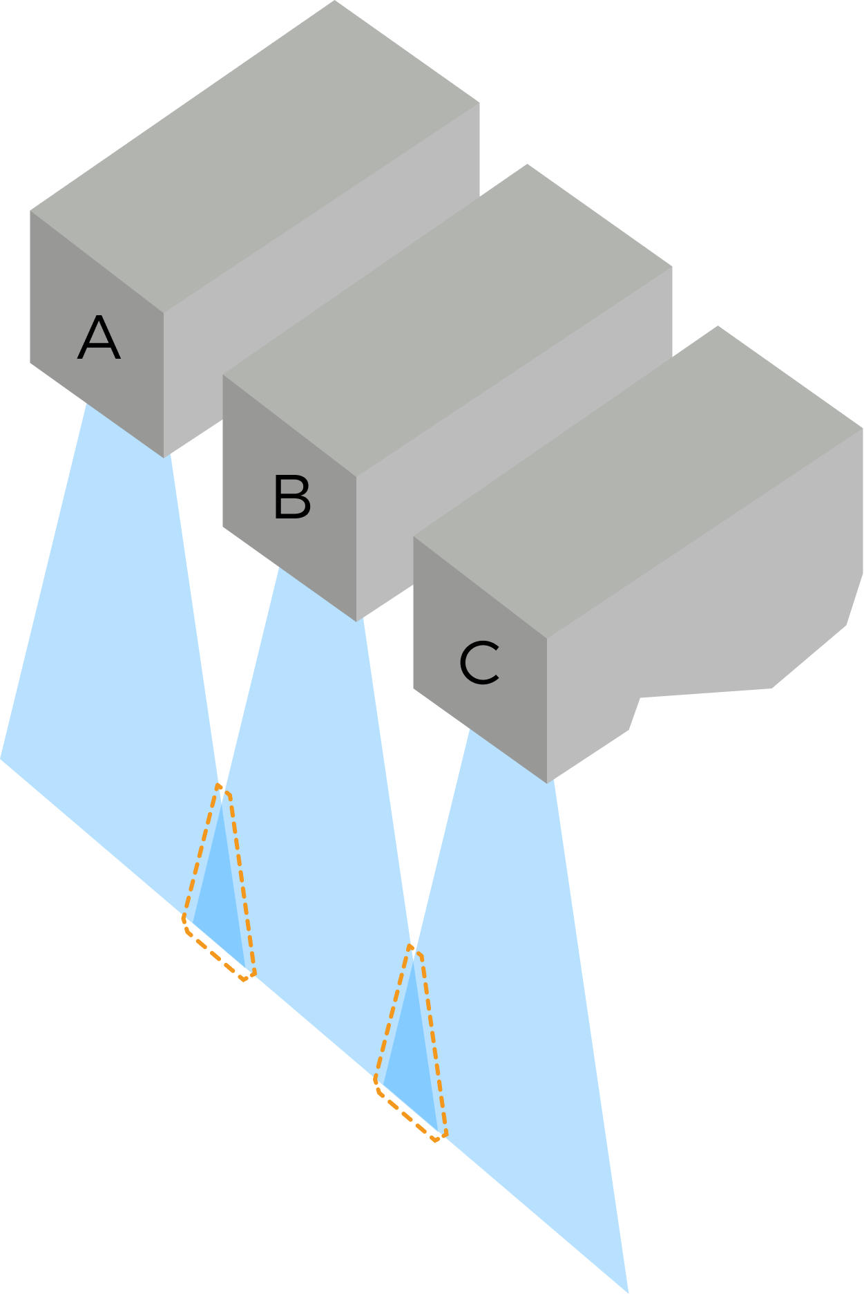
The purpose of adjusting Trigger Delay is to avoid interference in overlapping FOVs. Since laser profilers A and C in the image to the right of the table do not overlap, they can emit laser light simultaneously. You only need to adjust Trigger Delay for laser profiler B, making it emit laser light after laser profilers A and C.
-
Follow these steps to set Trigger Delay for laser profilers, referring to the spatial relationship examples and parameter settings in the table below:
-
Determine which laser profiler should emit laser light first, and keep the default Trigger Delay value of 0 for it.
-
Determine which laser profiler should emit laser light second, and set the value of Trigger Delay according to the following formula:
Trigger Delay = 10 μs + the Exposure Time (in the Timed exposure mode) or the Total exposure time in the HDR Exposure Settings (in the HDR exposure mode) of the laser profiler first to emit laser light
The laser profiler starts exposure 10 μs after emitting laser light to ensure stable brightness of the laser lines in the raw image. -
Determine which laser profiler should emit laser light third, and set the value of Trigger Delay according to the following formula:
Trigger Delay = the Trigger Delay value of the laser profiler second to emit laser light + 10 μs + the Exposure Time (in the Timed exposure mode) or the Total exposure time in the HDR Exposure Settings (in the HDR exposure mode) of the laser profiler second to emit laser light
-
Set the value of Trigger Delay for all laser profilers following this logic.
Example of spatial relationship
Parameter settings
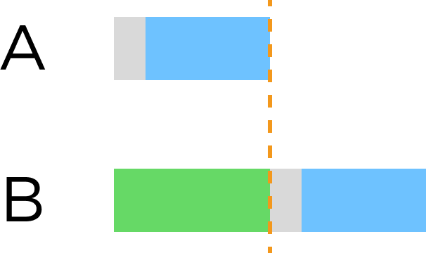
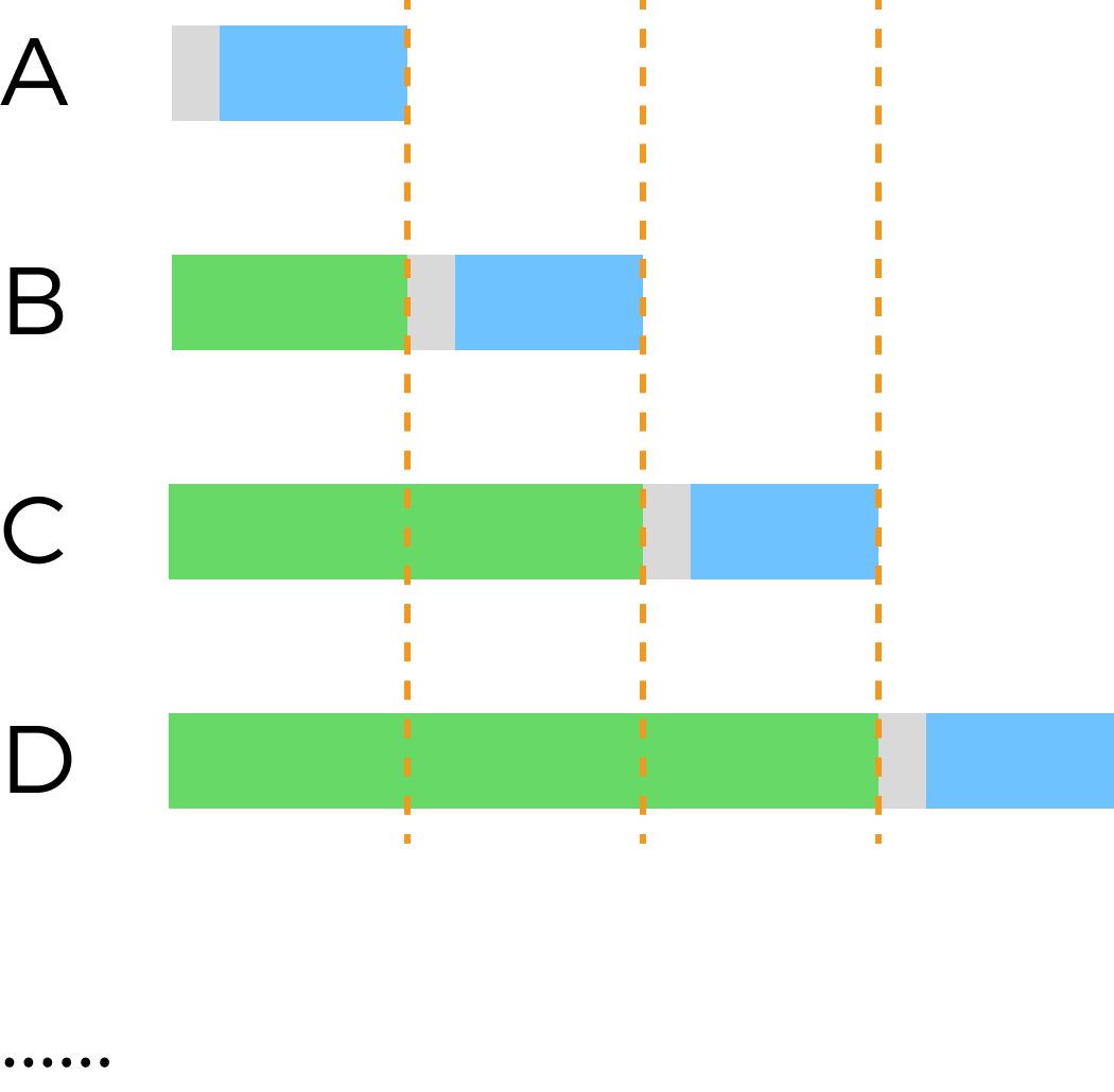
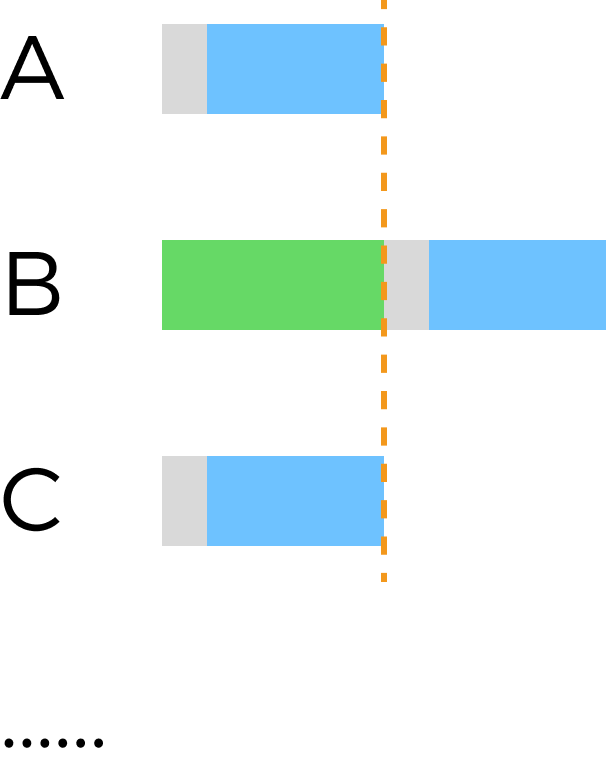
 : Exposure delay time:(10 μs)
 : Exposure Time/Total exposure time
 : Trigger Delay
-
2. Scan Settings
Set other parameters that affect the scanning process.
2.1. Scan Line Count
Description |
This parameter sets the number of profiles in the acquired data. |
||
|---|---|---|---|
Visibility |
Beginner, Expert, Guru |
||
Values |
|
||
Instructions |
|
2.2. Scan Distance
Parameter Description |
Displays the current scanned distance, calculated as follows : Scan Distance (μm) = Scan Line Count × Y-Axis Resolution (μm) |
|---|---|
Visibility |
Beginner, Expert, Guru |
Instruction |
This parameter is read-only and cannot be adjusted. |
2.3. Data Retrieval Timeout
Parameter Description |
This parameter sets the timeout period for data retrieval. After data acquisition is triggered, if the software does not receive data within the set timeout period, the current round of data acquisition is automatically stopped. |
|---|---|
Visibility |
Expert, Guru |
Values |
|
Instruction |
This parameter value should not be shorter than the time required to scan one line. If the line scan trigger frequency is low, increase this parameter. |
2.4. Brightness Adjustment
Parameter Description |
Adjust the brightness of the intensity image. A greater value of this parameter results in a brighter intensity image. |
|---|---|
Visibility |
Expert, Guru |
Values |
|
Instruction |
|
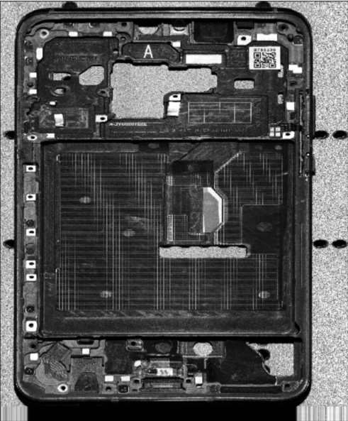
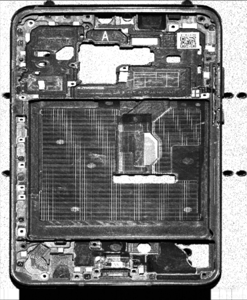
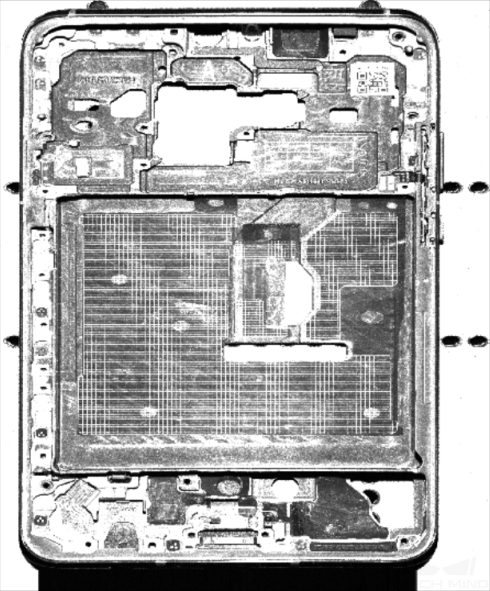
Intensity images with different Brightness Adjustment values (all other conditions identical):
| Brightness Adjustment: 0.5× | Brightness Adjustment: 1× | Brightness Adjustment: 2× |
|---|---|---|
|
|
|
3. Resolution
The parameters in this category set the X-axis resolution of the scan data and the Y-axis resolution of the point cloud.
3.1. X-Axis Resolution
Description |
Sets the X-axis resolution of the scan data, which is the distance between two neighboring points along the direction of the laser line. |
||
|---|---|---|---|
Visibility |
Beginner, Expert, Guru |
||
Values |
|
||
Instruction |
|
3.2. Y-Axis Resolution
Parameter Description |
Sets the Y-axis resolution of the scan data, which is the distance between two neighboring points along the travel direction of the target object. |
|---|---|
Visibility |
Beginner, Expert, Guru |
Instruction |
This parameter is read-only and cannot be adjusted. The calculation method is as follows:
|
4. Mask
Description |
Use masks to exclude unneeded data, such as noise and laser lines produced by interreflection. |
|---|---|
Visibility |
Beginner, Expert, Guru |
Values |
Enable Mask toggle switch:
|
Instruction |
Click Edit to open the Mask Tool window. For detailed instructions, refer to Use Mask Tool below. |
4.1. Use Mask Tool
Through the mask tool, you can add, edit, and delete masks.
4.1.1. Add Masks
Follow these steps to add masks:
-
Select the appropriate tool in the toolbar on the left:
-
 : used to add a rectangle mask.
 -
 : used to add a polygon mask.
-
-
Determine the location of the unneeded data in the raw image and draw a mask:
-
Rectangle mask: Hold and drag.
-
Polygon mask: Click to add a vertex of the polygon mask. After all needed vertices are added, press the Enter key or right-click to finish drawing the polygon mask.
In a polygon mask, the overlapped regions are not effective:

-
Click Acquire again at the top to acquire the raw image after the masks are added to check the effect of the masks.
-
If the position, shape, or size of the masks are not satisfactory, you can edit the masks or delete the masks.
-
-
-
After all masks are added, click Apply to close the current window.
After you click Apply, the Enable Mask toggle switch will be turned on automatically. If the masks do need to be applied, turn off the toggle switch and acquire data again.
4.1.2. Edit Masks
If the position, shape, or size of the masks are not satisfactory, follow these steps to edit the masks:
-
Click
 in the toolbar on the left.
 -
Select the mask that needs to be edited and conduct the needed adjustment:
-
Move a mask: Select the mask and drag.
-
Adjust the size of a rectangle mask: Select a vertex of the rectangle mask and drag.
-
Adjust the shape of a polygon mask:
-
Move an existing vertex: Select a vertex of the polygon mask and drag.
-
Add a new vertex: Left-click on an edge of the polygon mask.
-
Delete an existing vertex: Select a vertex of the polygon mask and right-click.
Click Acquire again at the top to acquire the raw image after the masks are edited to check the effect of the masks.
-
-
-
After all editing is completed, click Apply to close the current window.
After you click Apply, the Enable Mask toggle switch will be turned on automatically. If the masks do need to be applied, turn off the toggle switch and acquire data again.
4.1.3. Delete Masks
Follow these steps to delete unsatisfactory masks:
-
In the right panel, select the mask that needs to be deleted in Mask list, and click
 .
.If you need to delete all the masks, click Clear to the right of Mask list. -
In the pop-up window, click Confirm to delete the mask.
Click Acquire again at the top to acquire the raw image after the mask is deleted to check the effect of the remaining masks. -
After all deletion is completed, click Apply to close the current window.
After you click Apply, the Enable Mask toggle switch will be turned on automatically. If the masks do need to be applied, turn off the toggle switch and acquire data again.
5. Profile Alignment
The parameters in this category correct the X-axis and Z-axis vibrations in the profiles.
5.1. X-Axis Profile Alignment
Description |
This tool corrects the X-axis vibrations in the profiles. |
|---|---|
Visibility |
Expert, Guru |
Values |
Enable X-Axis Profile Alignment toggle switch:
|
Instruction |
Acquire data, and then click Edit to open the tool. For detailed instructions, refer to X-Axis Profile Alignment. |
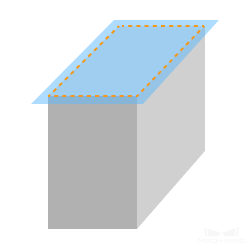
Depth maps before and after turning on X-Axis Profile Alignment (all other conditions identical):
| Target object (demonstration) | Before | After |
|---|---|---|
|
|
|

5.2. Z-Axis Profile Alignment
Description |
This tool corrects the Z-axis vibrations in the profiles. |
|---|---|
Visibility |
Expert, Guru |
Values |
Enable Z-Axis Profile Alignment toggle switch:
|
Instruction |
Acquire data, and then click Edit to open the tool. For detailed instructions, refer to Z-Axis Profile Alignment. |
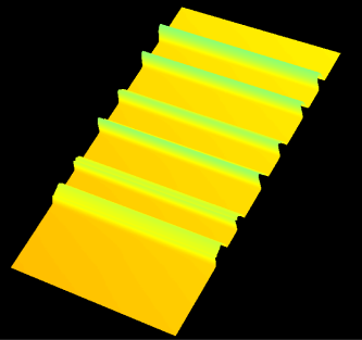
Point clouds before and after turning on Z-Axis Profile Alignment (all other conditions identical):
| Target object (demonstration) | Before | After |
|---|---|---|
|
|
|

6. Correction
The parameters in this category are used to correct the tilt of and height error in the profile.
6.1. Tilt Correction
Parameter Description |
Correct the tilt of the profile, which is caused by the rotation of the laser profiler around the Y-axis. |
|---|---|
Visibility |
Beginner, Expert, Guru |
Values |
Enable Tilt Correction toggle switch:
Tilt Correction Angle:
|
Instruction |
For detailed instructions, refer to Tilt Correction. |
6.2. Height Correction
Parameter Description |
Correct the height error in the profile, which is caused by the rotation of the laser profiler around the X-axis. |
|---|---|
Visibility |
Beginner, Expert, Guru |
Values |
Enable Height Correction toggle switch:
Height Correction Ratio:
|
Instruction |
For detailed instructions, refer to Height Correction. |
7. Filtering
The parameters in this category perform blind spot filtering and noise removal on the depth map and point cloud.
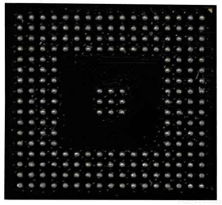
7.1. Blind Spot Filtering
Blind spots are the areas on the target object surface where reflected laser lights are blocked.
However, if the surface of the target object has closely-spaced dents and bumps, such as PCBs, interreflection of the laser light might occur, thus producing false data near the blind spots. You can remove the false data by enabling the Blind Spot Filtering feature.
Description |
Identifies and removes false data caused by blind spots, thereby avoiding influence on further data processing. |
|---|---|
Visibility |
Expert, Guru |
Values |
Enable Blind Spot Filtering toggle switch:
Y-axis resolution: Displays the Y-axis resolution of the scan data. Filtering intensity: Displays the intensity of blind spot filtering.
|
Instruction |
Acquire data, and then click Edit to open the tool. For detailed instructions, refer to Blind Spot Filtering. |
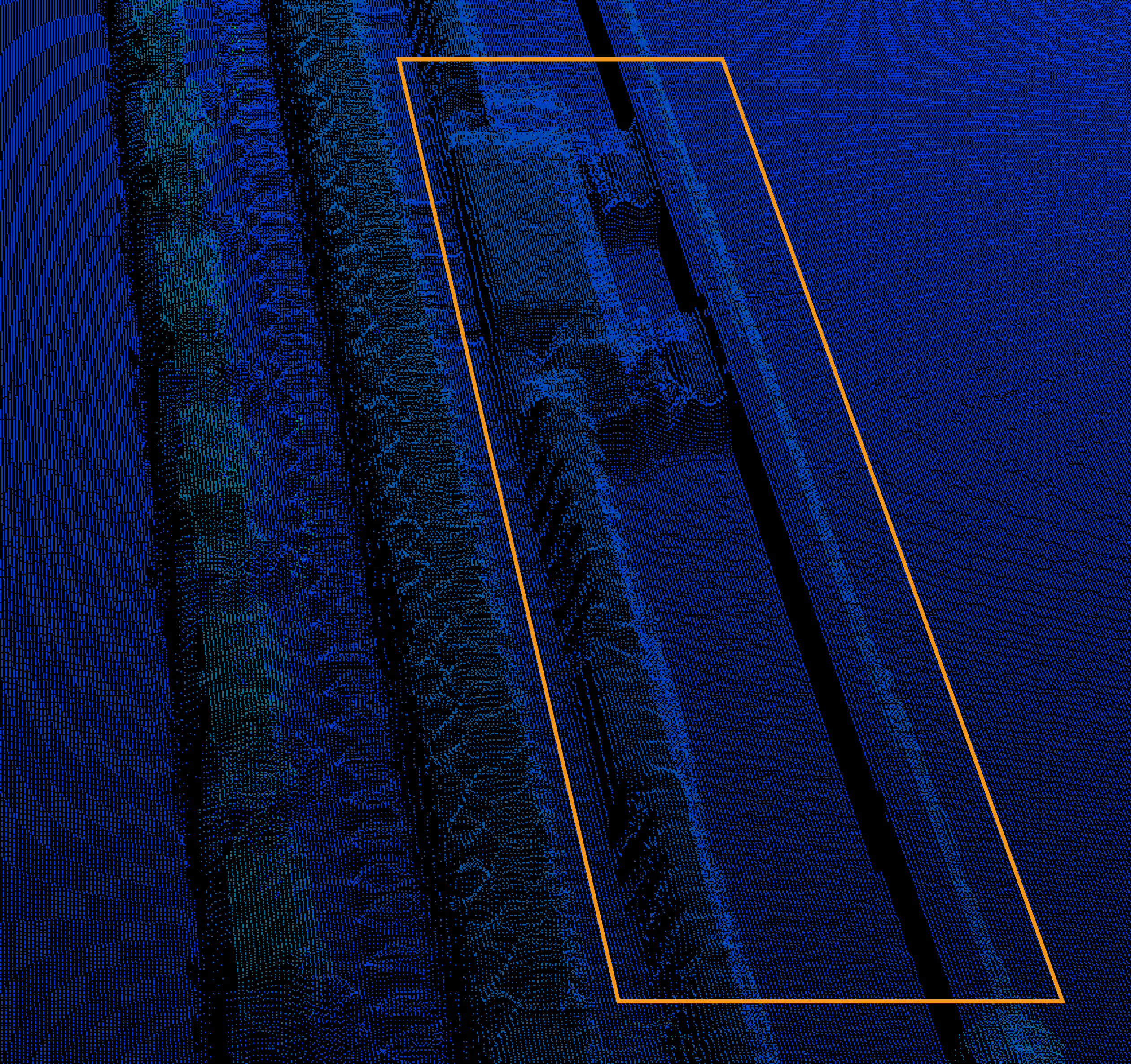
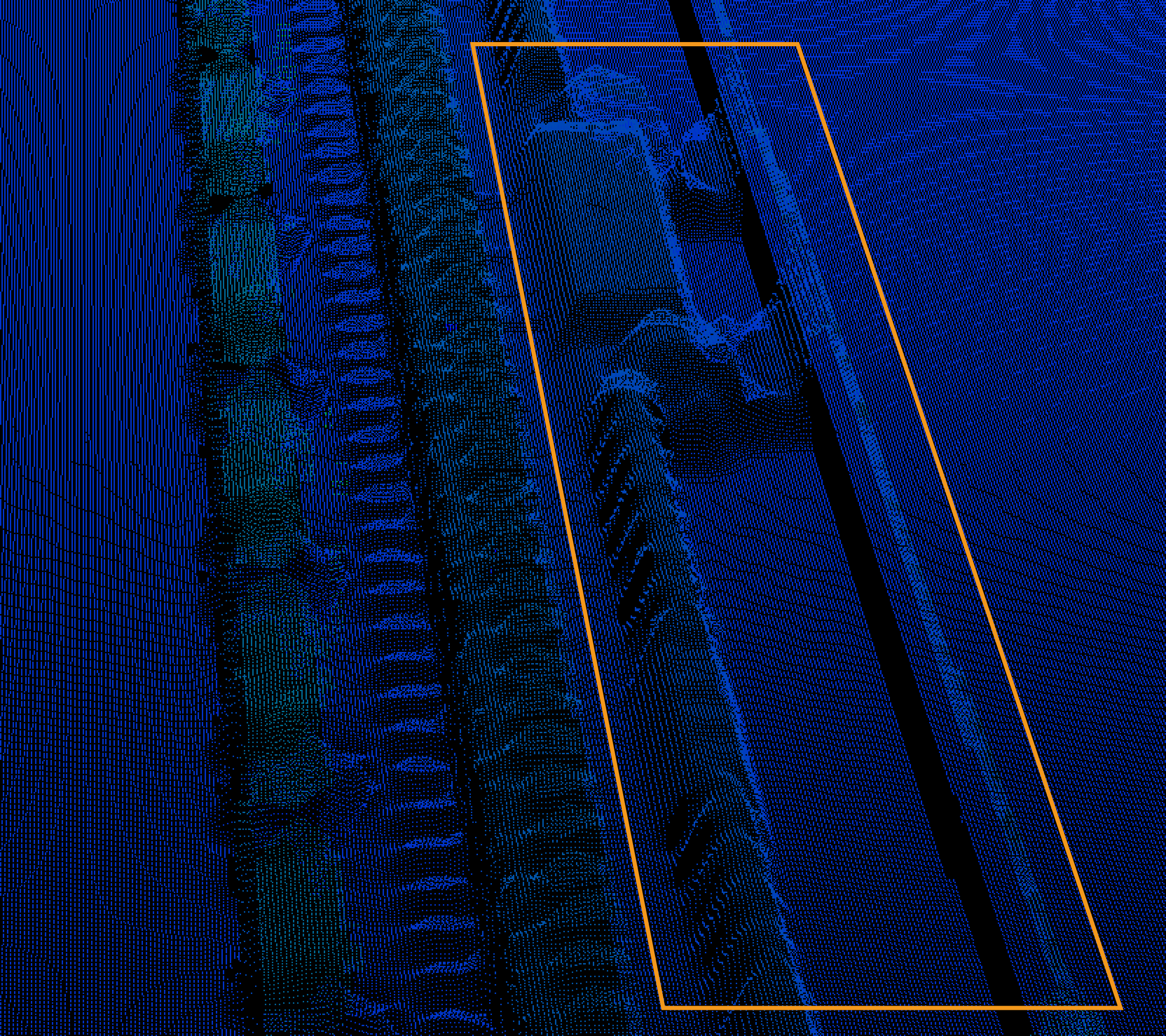
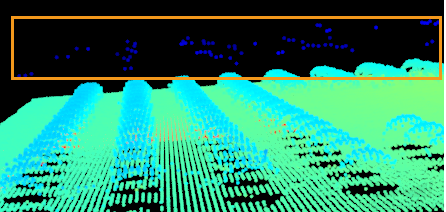
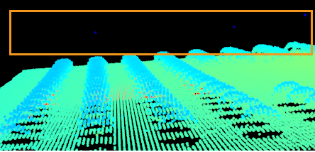
Point clouds before and after turning on Blind Spot Filtering (all other conditions identical):
| Target object | Before | After |
|---|---|---|
|
|
|
7.2. Noise Removal
Description |
Removes the noise in the depth map and point cloud. Noise is the scattered points close to the object surface. |
|---|---|
Visibility |
Expert, Guru |
Values |
Enable Noise Removal toggle switch:
Noise Removal Intensity:
|
Instruction |
|
Point clouds before and after turning on Noise Removal (all other conditions identical):
| Target object | Before | After |
|---|---|---|
|
|
|