X-Axis Profile Alignment
This tool corrects the X-axis vibrations in the profiles. By selecting edges that need to be corrected on the target object, and setting the values of Edge height and Vibration tolerance with this tool, you can correct distortion in these edges caused by profile vibrations.
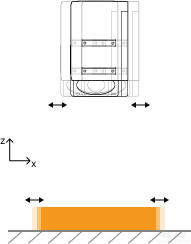
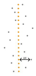
Vibration of the target object or sensor head along the X-axis, as shown in the image below, results in vibrations in the profiles along the X-axis.
Depth maps before and after turning on X-Axis Profile Alignment (all other conditions identical):
| Target object (demonstration) | Before | After |
|---|---|---|
|
|
|


Follow these steps to perform X-axis profile alignment:
-
Click the button
 in the data acquisition area to trigger one round of data acquisition.
 -
In the scan mode, click Edit on the right of X-Axis Profile Alignment to open the X-Axis Profile Alignment tool.
-
Select a proper tool in the left toolbar, and then add or adjust correction area(s) in the depth map.
You can add up to five correction areas.
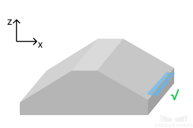
A correction area is used to select an edge to be corrected on the target object. The edge to be corrected will be fitted into a straight line which serves as the target edge.
To ensure the effect of profile alignment, each correction area should:
-
Not overlap with others.
-
Contain only one edge (i.e., the edge to be corrected) on the target object. Meanwhile, the edge should:
-
Be a straight line.
-
Consist of points that have pronounced height difference with the neighboring point on the X-axis.
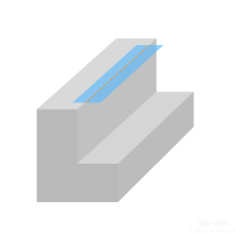
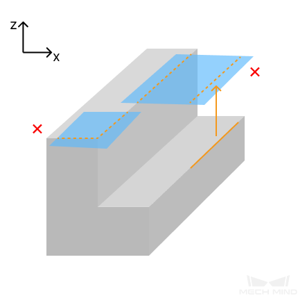
Right Wrong 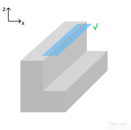
-
The correction area contains more than one edge.
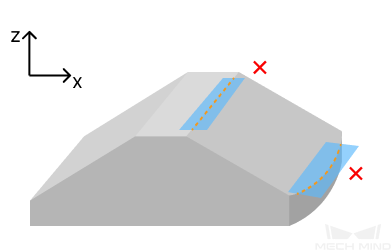
-
The height difference between the points on the edge and their neighboring points on the X-axis is too small.
-
The edge is a curved line.
-
-
-
-
Set Edge height to a value slightly smaller than the height difference (i.e., ΔZ in the image below) between the points on the edge to be corrected and their neighboring points on the X-axis but greater than the depth value fluctuation in the correction area.
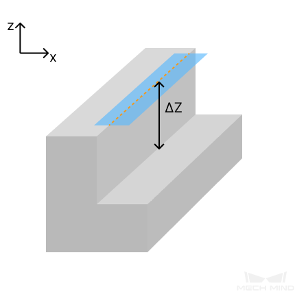
If you have added more than one correction area, ensure that the value of Edge height is slightly smaller than all ΔZ values but greater than the depth value fluctuations in all correction areas.
The value range and increment of Edge height of various laser profiler models are as follows:
Model Value range (mm) Increment (mm) LNX-7515-GL
0–8.0
0.1
LNX-7530-GL
0–25.0
LNX-7580-GL
0–80.0
LNX-75150-GL
0–231.0
LNX-75300-GL
0–295.0
LNX-8030-GL
0–30.0
LNX-8080-GL
0–100.0
LNX-8300-GL
0–305.0
-
Set Vibration tolerance. Points on the edge to be corrected whose distances to the target edge are equal to or larger than the value of Vibration tolerance will be aligned with the target edge. Points whose distances to the target edge are smaller than the value of Vibration tolerance will remain unchanged.
If you have added more than one correction area, all points on the edges to be corrected in all correction areas will be aligned according to the set value of Vibration tolerance.
The value range and increment of Vibration tolerance of various laser profiler models are as follows:
Model Value range (mm) Increment (mm) LNX-7515-GL
0–15.5
0.1
LNX-7530-GL
0–40.0
LNX-7580-GL
0–100.0
LNX-75150-GL
0–190.0
LNX-75300-GL
0–450.0
LNX-8030-GL
0–40.0
LNX-8080-GL
0–100.0
LNX-8300-GL
0–450.0
-
Click Align to check the effect of X-axis profile alignment.
-
If the alignment effect fulfills requirements, click Apply to apply settings and exit the X-Axis Profile Alignment tool.
After you click Apply, the Enable X-Axis Profile Alignment toggle switch will be turned on automatically. During the next data acquisition, blind spot filtering will be performed according to the settings in the tool.
If X-axis profile alignment is not needed, turn off the toggle switch and acquire data again.
-
If the alignment effect does not fulfill requirements, repeat steps 3 to 6.
-
-
Acquire data again to obtain the depth map and point cloud with X-axis profiles aligned.