Multiple Laser Profiler Calibration
In industrial production, multiple laser profilers may be deployed together to scan the target object, thereby expanding the field of view and eliminating visual blind spots. The laser profilers should be calibrated before scanning the same target object. The calibration procedure includes arranging the calibration target and laser profilers, adjusting parameters and calibrating.
Arrange Calibration Target and Laser Profilers
Prepare for calibration following these steps.
-
Arrange the calibration target and laser profilers, and ensure that:
-
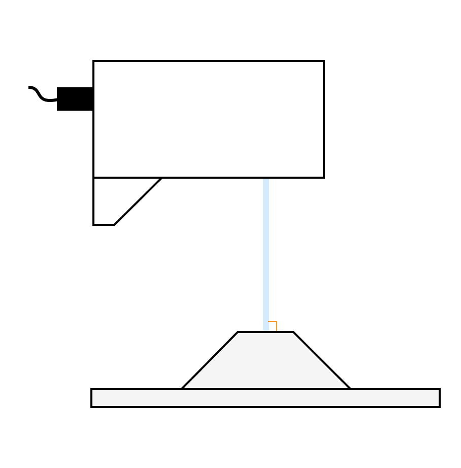
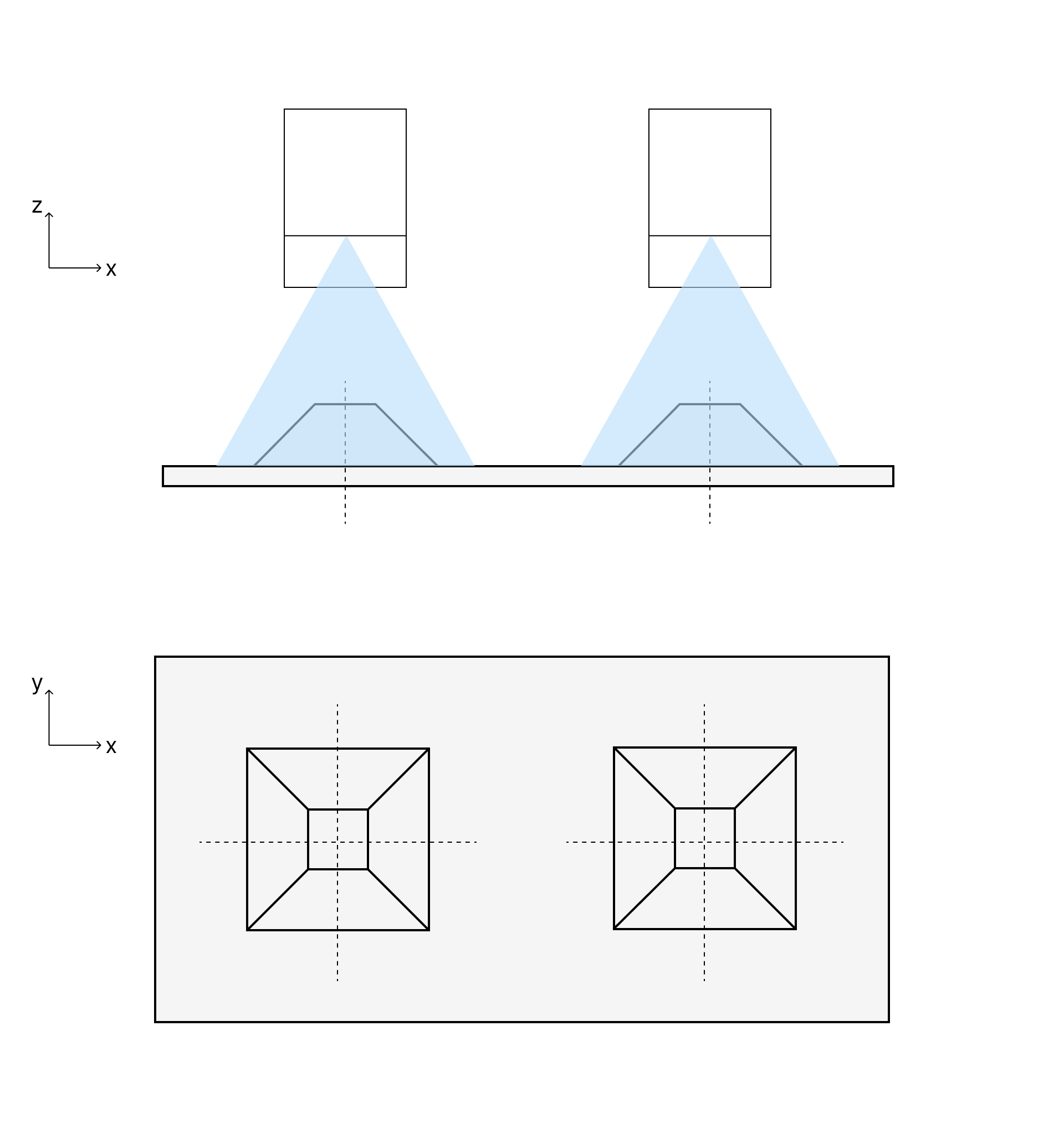
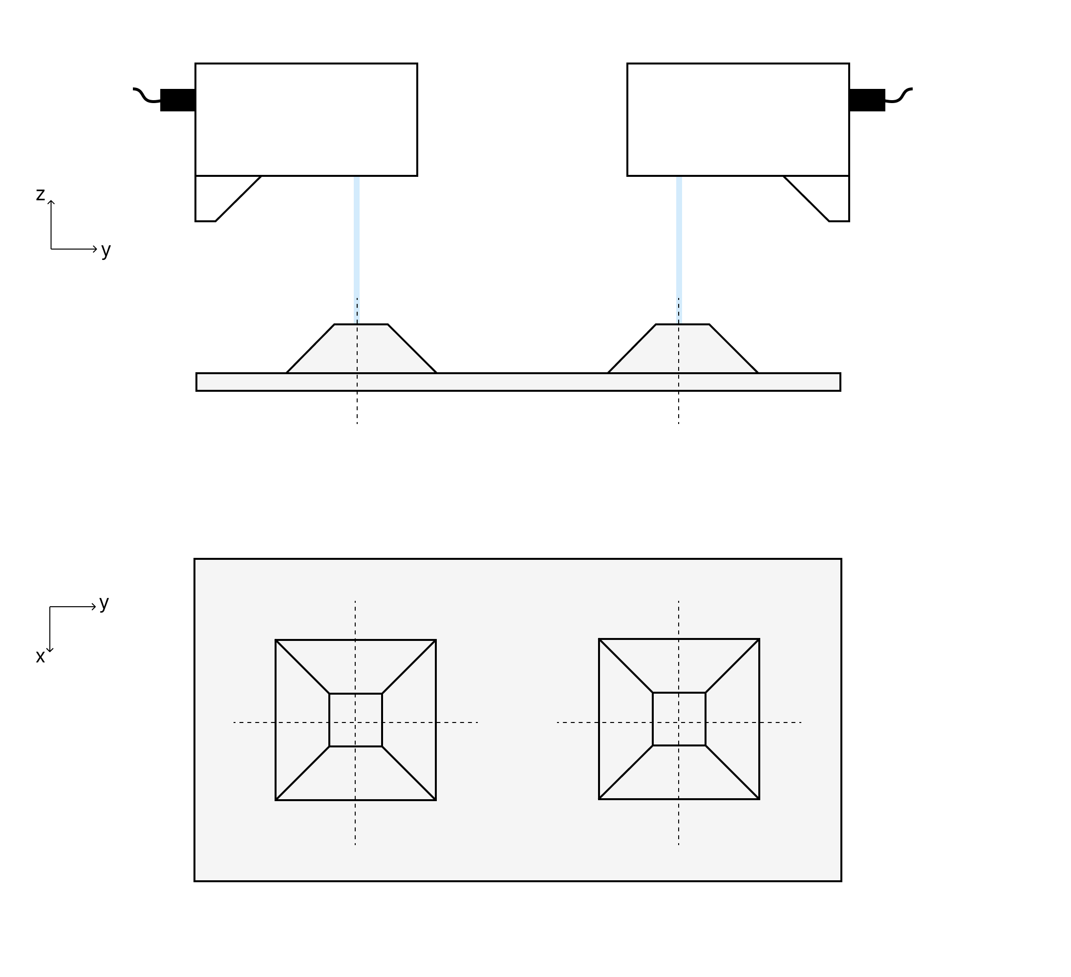
The laser projected by the laser profiler is perpendicular to the surface of the frustum.
-
The frustum is positioned at the center of the laser profiler’s FOV.


-
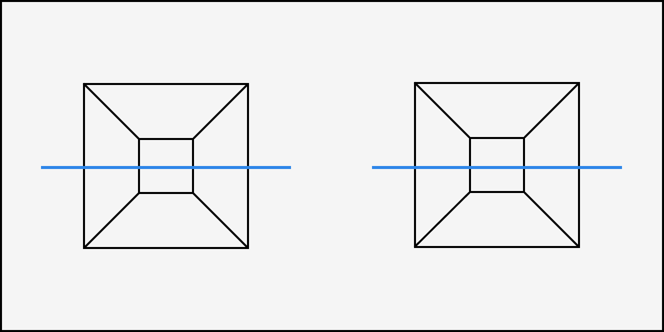
Four edges of the frustum are parallel to the emitted laser lines.
-
The foundation surface of the calibration target is positioned at the laser profiler’s reference distance (RD as shown in the figure).

If on-site conditions are limited, you can slightly move the calibration target upward toward the laser profiler.
-
-
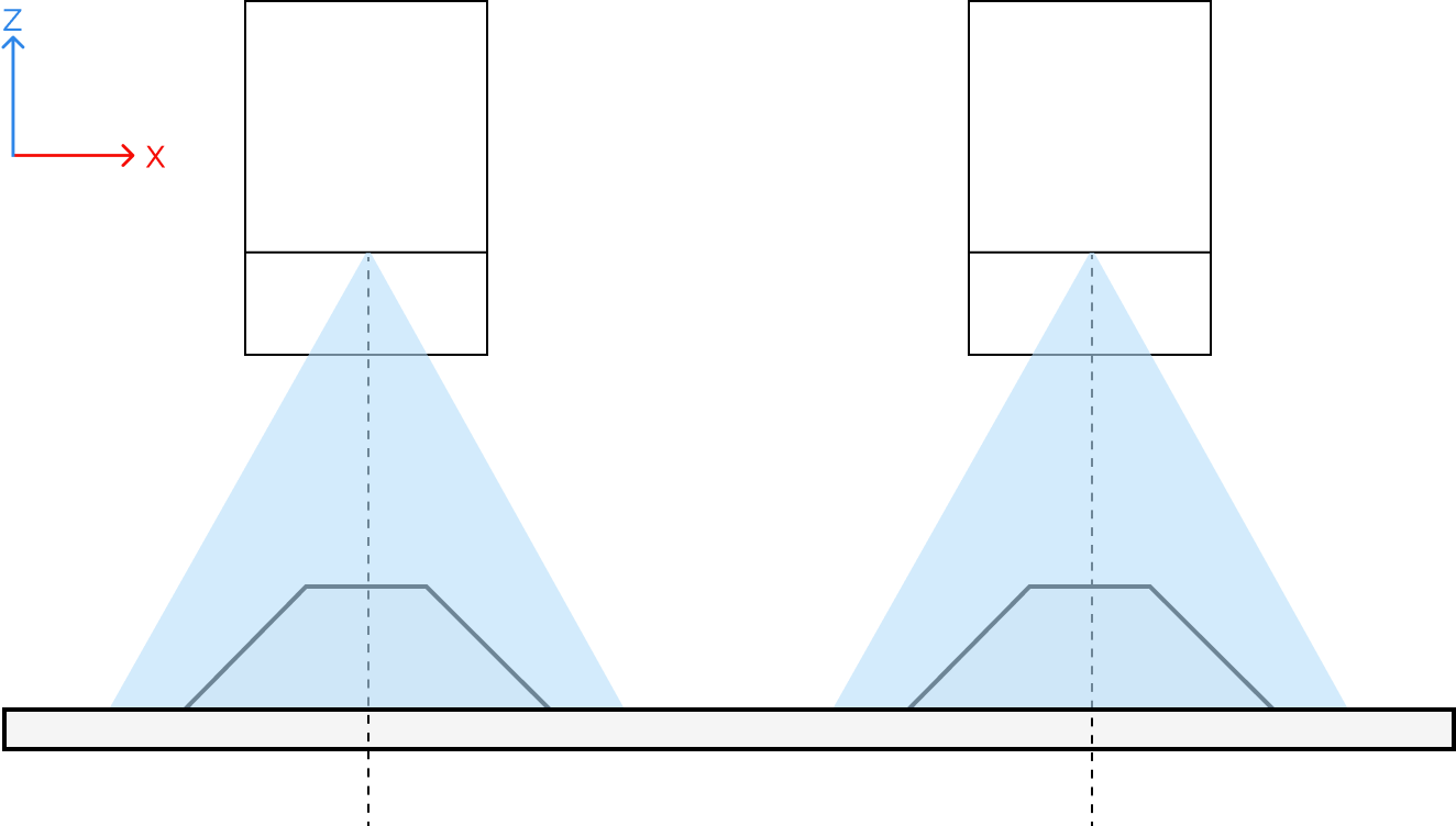
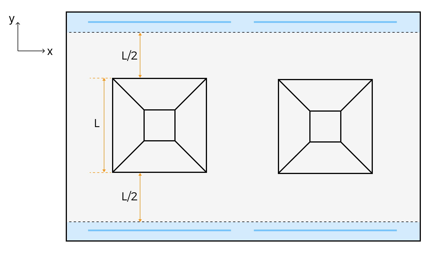
Determine the scan range: The distances from the scan start and end positions to the edges of the frustum’s lower base should both be greater than half the lower base length. In other words, both the scan start and end positions should fall within the blue areas of the target object, as shown in the table below.
After determining the scan range, adjust the translation stage so that the laser light emitted by the laser profiler falls on the scan start position. This facilitates data acquisition and data quality evaluation during parameter adjustment.
Layout
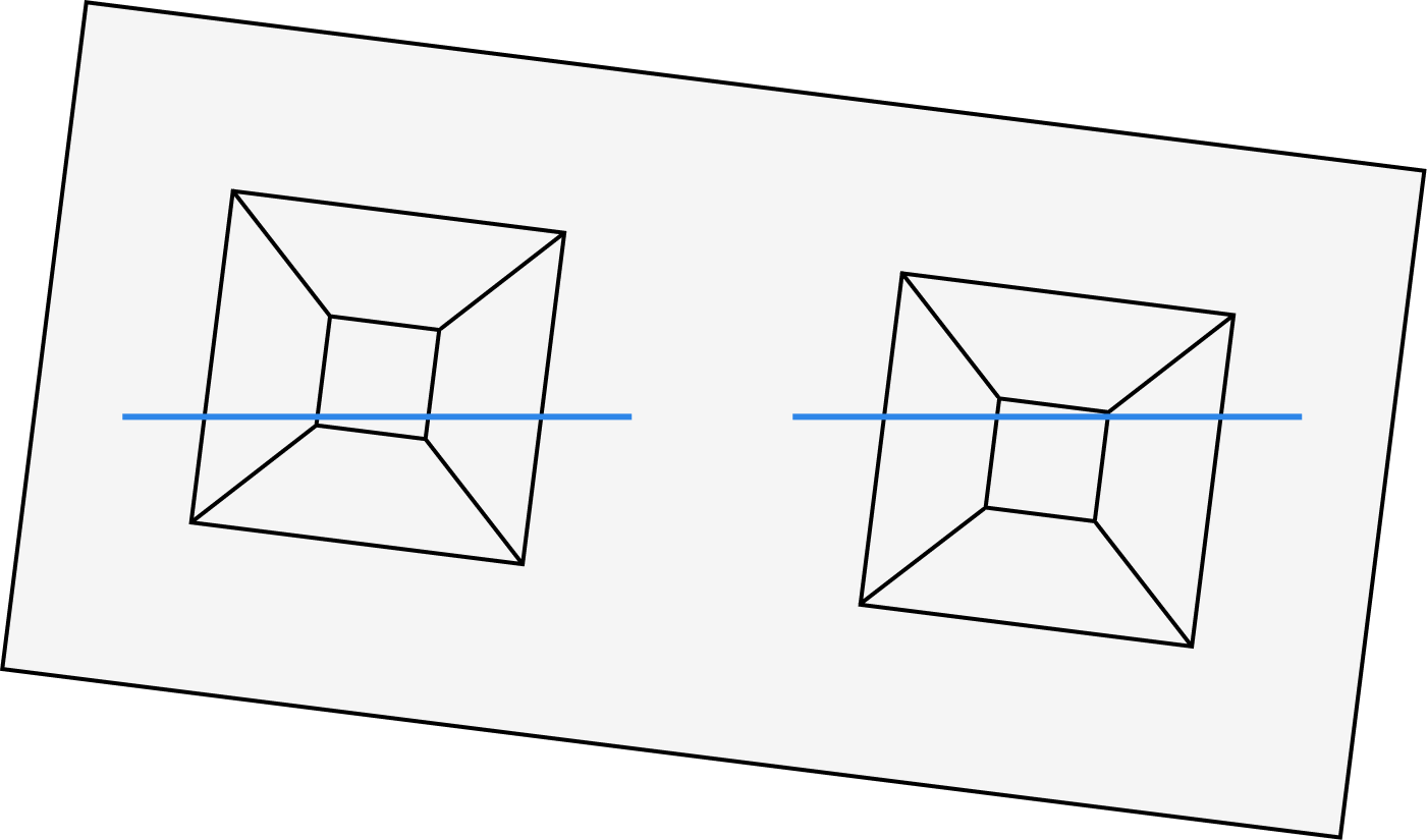
Side-by-side
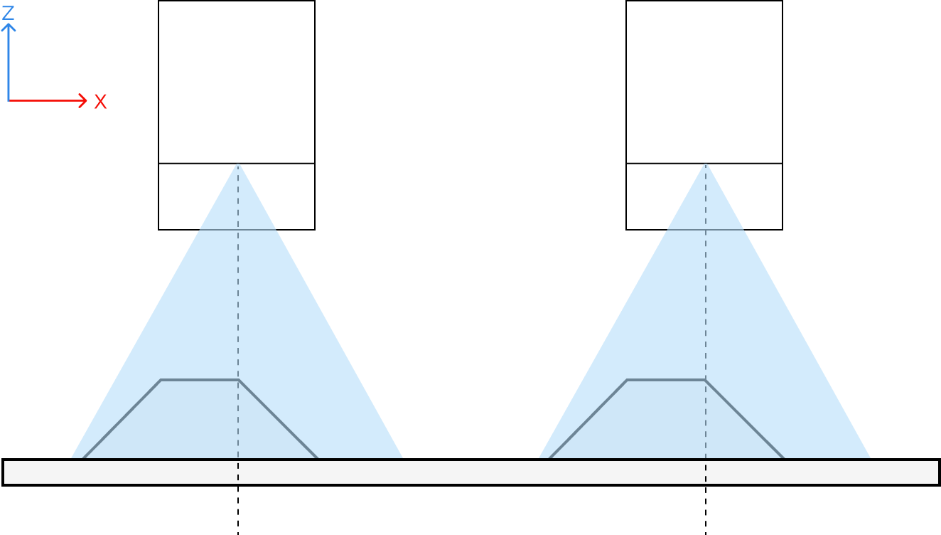
Reverse
Illustration
Scan start and end positions
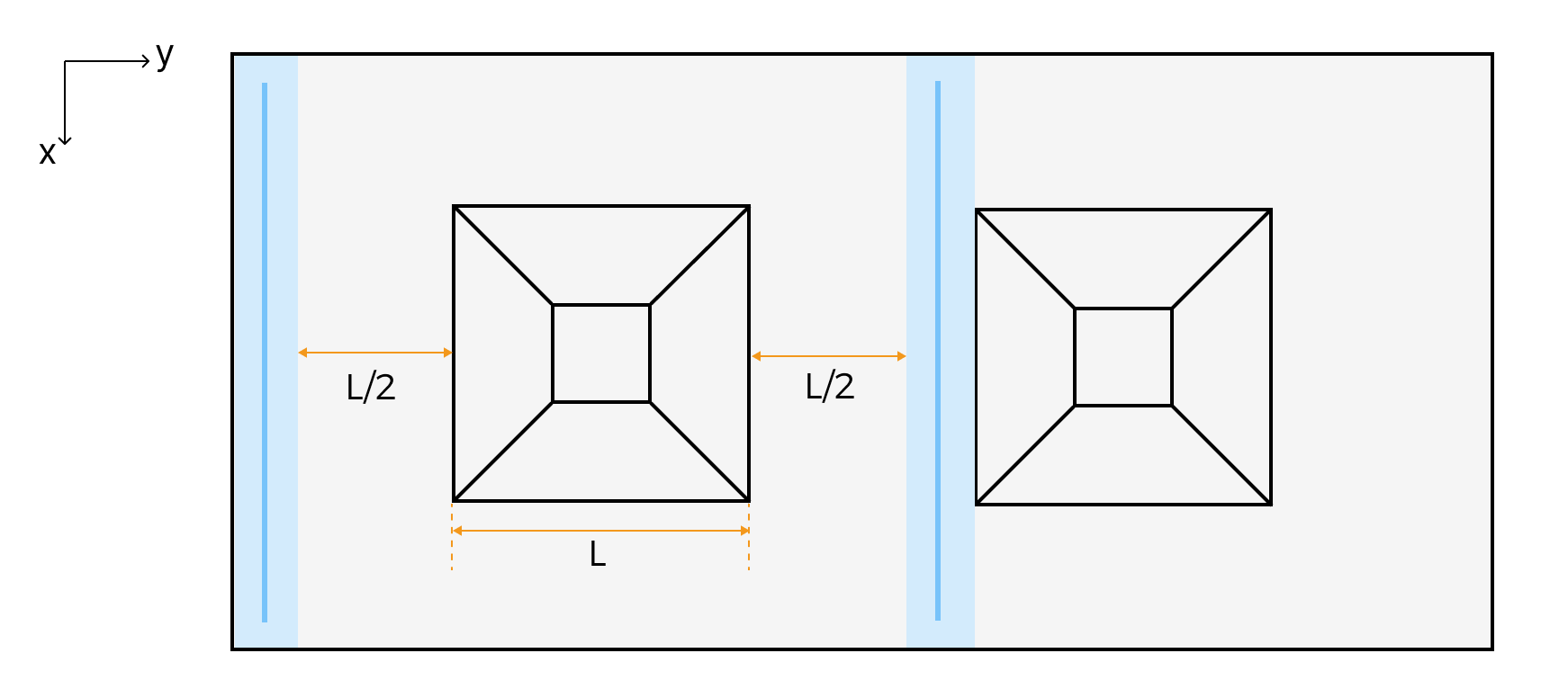
The laser profiler on the left in the figure above
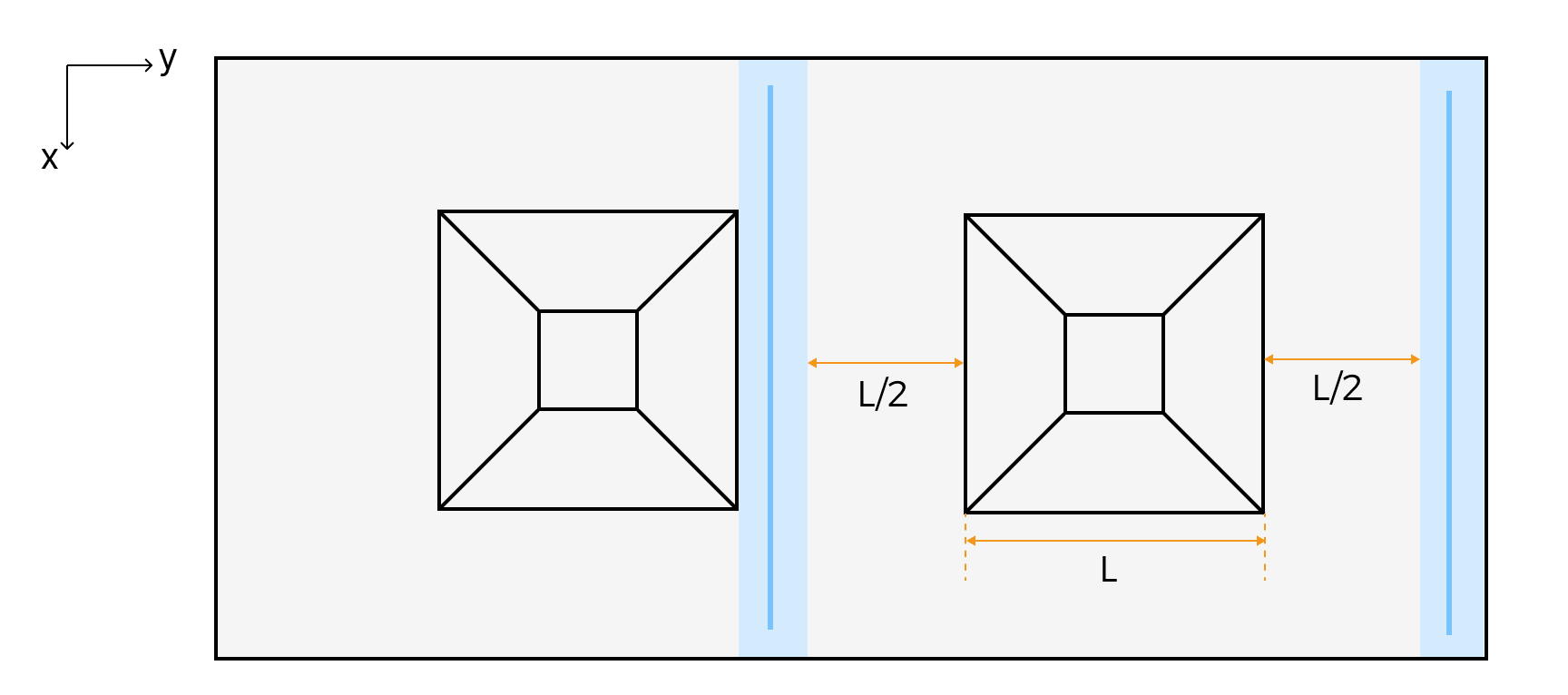
The laser profiler on the right in the figure above
-
Clean the surfaces of the calibration target and the windows of the laser profiler to prevent dust and stains from affecting data quality.
-
Ensure that there are no reflective objects near the calibration target that could interfere with data acquisition. If any are present, remove or cover them.
Adjust Parameters
Adjust parameters for each laser profiler according to the guide.
Calibration
Follow the steps below to perform calibration:
-
Warm-up: use the Warm-Up Tool to warm up the product, and adjust the warm-up time based on the actual data acquisition interval, ambient temperature, and heat-dissipation conditions.
-
Calibrate multiple laser profilers:
-
If using the Mech-MSR software, first select a calibration scene, and then follow the instructions to complete calibration.
During calibration, refer to Workflow of Triggering Data Acquisition to acquire data.
-
If using Mech-Eye API, refer to the sample MultipleProfilersCalibration.
-
During calibration, refer to Workflow of Triggering Data Acquisition to acquire data.
-
The moveDirSign parameter in the sample is determined by the motion direction of the target object relative to the laser profiler:
Motion direction of the target object
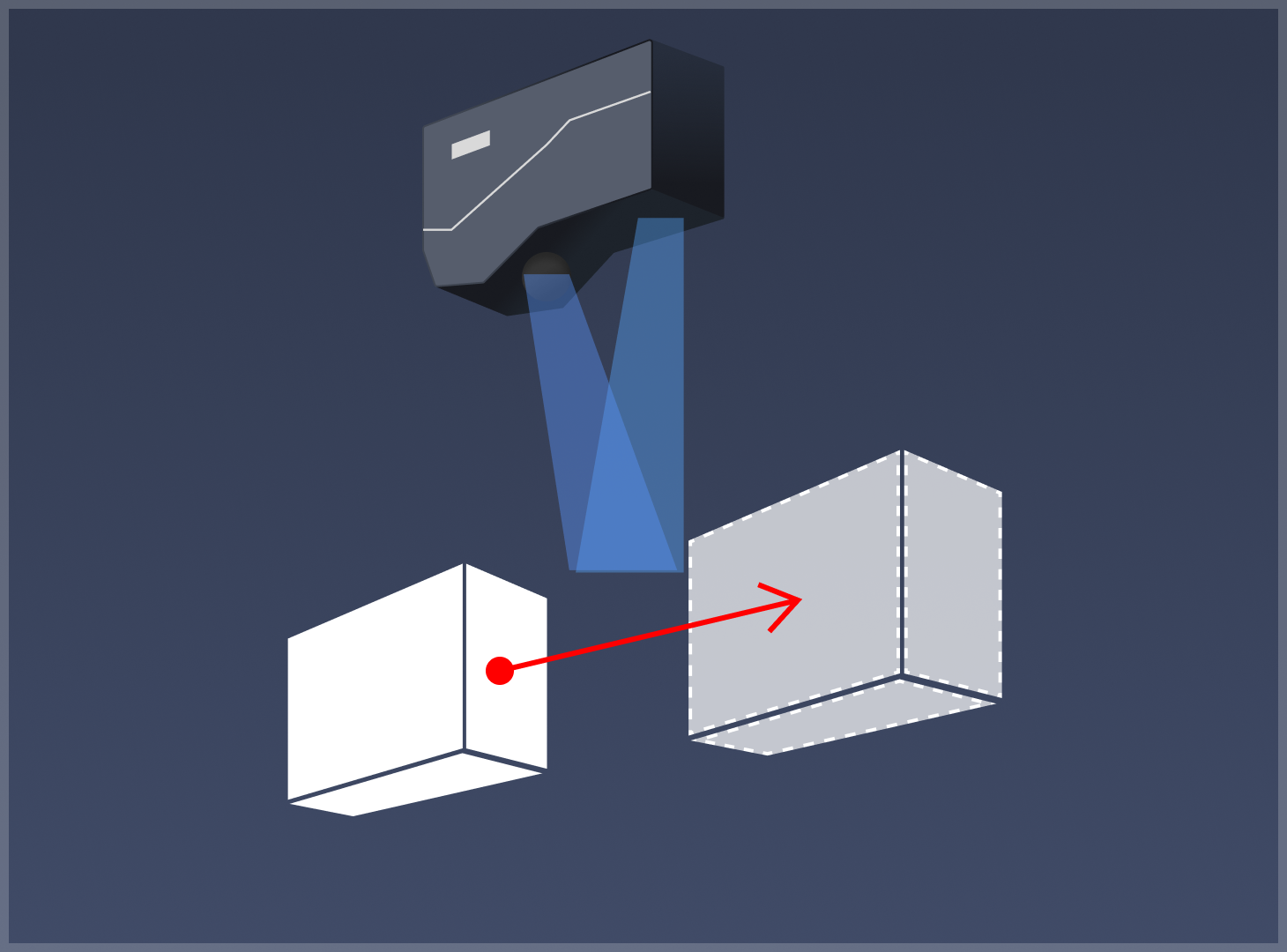
From sensor to laser emitter
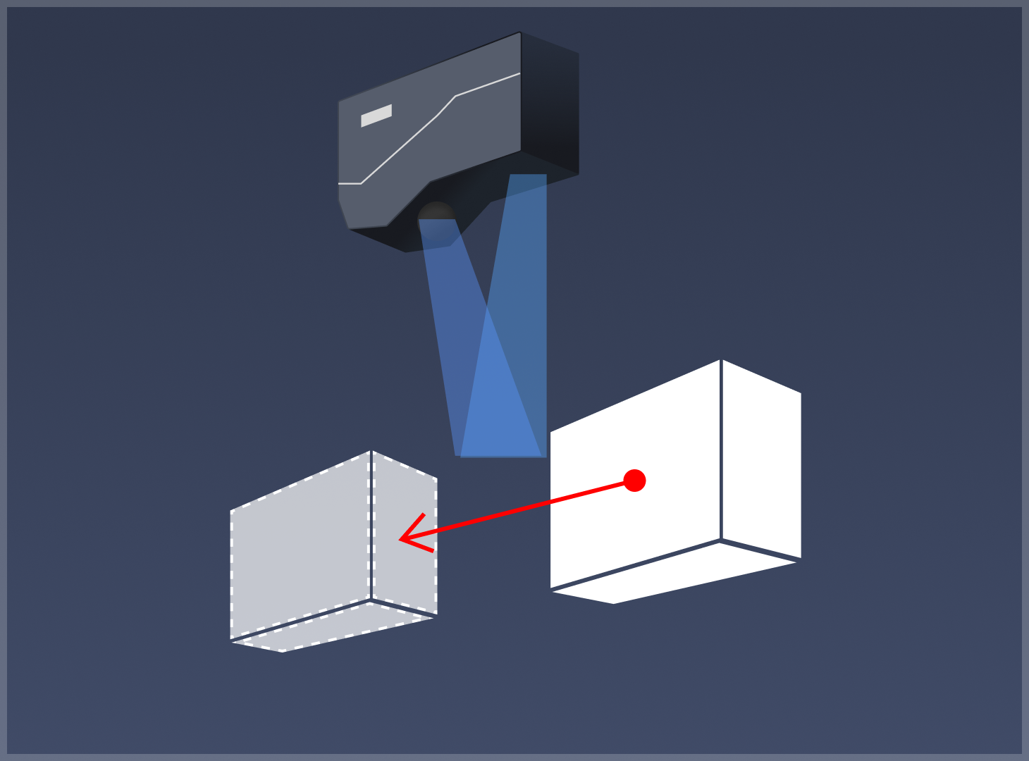
From laser emitter to sensor
moveDirSign parameter value
True
False
-
-