Encoder Settings
This tool is used to check the encoder value and motion direction and calculate the encoder resolution.
If you need the Y-axis resolution of the scan data to be equal to the X-axis resolution, you can use this tool to get the recommended trigger interval.
In the scan mode, click Edit to the right of Encoder Settings in the Parameters tab to open the Encoder Settings tool.
|
Check Encoder Value and Motion Direction
At the top of the tool window, you can check the Encoder value and Motion direction.
-
Encoder value: displays the encoder value in real time.
-
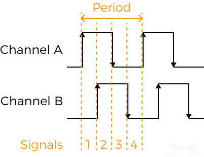
Motion direction: displays the motion direction of the encoder (Channel A leading or Channel B leading) based on how the encoder value changes when the encoder is functioning.
Calculate Encoder Resolution
The encoder resolution is the travel distance corresponding to one quadrature signal, in other words, the travel distance of the target object relative to the laser profiler corresponding to one signal in the image. The encoder resolution is measured in μm. The encoder resolution can be used to get the recommended trigger interval.
This tool automatically calculates the encoder resolution based on the moving distance of the object relative to the laser profiler and the corresponding encoder value.
|
The calculated encoder resolution may show some degree of inaccuracy. |
Follow these steps to calculate the encoder resolution:
-
Select Calculate resolution in the Encoder resolution calculator section.
-
Click Update to the right of Start value.
-
Make the object move relative to the laser profiler. After the object stops moving, click Update to the right of End value.
-
Measure the relative travel distance between the object and the laser profiler, and enter the value into Travel distance.
-
Click Calculate. The encoder resolution will be displayed in the Encoder resolution text box.
Get Recommended Trigger Interval
A proper value of Trigger Interval ensures that the Y-axis resolution of the scan data is basically equal to the X-axis resolution, thus producing intensity images and depth maps that match the aspect ratios of the actual object.
The Encoder Settings tool can calculate a recommended Trigger Interval, and apply the value to the Parameters tab.
Follow these steps to calculate Recommended trigger interval with the Encoder Settings tool:
-
Enter or calculate the encoder resolution. This tool automatically calculates Recommended trigger interval based on the current values of Encoder resolution and Trigger signal counting mode.
-
Click Apply to close the window. In the scan mode, acquire data again and check the aspect ratio of the target object in the intensity image and depth map.
-
If the aspect ratio matches the actual object, the process is completed.
-
If the aspect ratio does not match the actual object, proceed to the next step.
-
-
Check the set value of Trigger Signal Counting Mode:
-
If it is 1× or 2×, proceed to step 4.
-
If it is 4×, proceed to step 7.
-
-
Click Edit to the right of Encoder Settings to open the Encoder Settings tool.
-
Increase the value of Trigger Signal Counting Mode.
-
Click Apply to close the window. In the scan mode, acquire data again and check the aspect ratio of the target object in the intensity image and depth map.
-
If the aspect ratio matches the actual object, the process is completed.
-
If the aspect ratio does not match the actual object, repeat step 3.
-
-
Slightly adjust Trigger Interval in the Parameters tab according to the aspect ratio of the target object in the intensity image and depth map.
-
If the images appear compressed relative to the actual object, increase the value of Trigger Interval by 1.
-
If the images appear stretched relative to the actual object, decrease Trigger Interval by 1.
-
-
In the scan mode, acquire data again and check the aspect ratio of the target object in the intensity image and depth map.
-
If the aspect ratio matches the actual object, the process is completed.
-
If the aspect ratio does not match the actual object, repeat step 7.
If the Y-axis resolution of the scan data cannot be set to the same value as the X-axis resolution by adjusting Trigger Interval, you can adjust X-axis resolution.
-