Getting Started with the Camera
This chapter walks you through the complete workflow, from unboxing inspection to image acquisition with the 2D smart camera.
Check Package Contents
-
After receiving the camera package, confirm that the package is intact and undamaged.
-
Find the Package Contents list and verify that all items and accessories are present and undamaged.
Check Interfaces and Indicator Lights
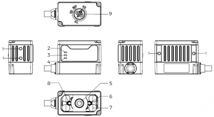
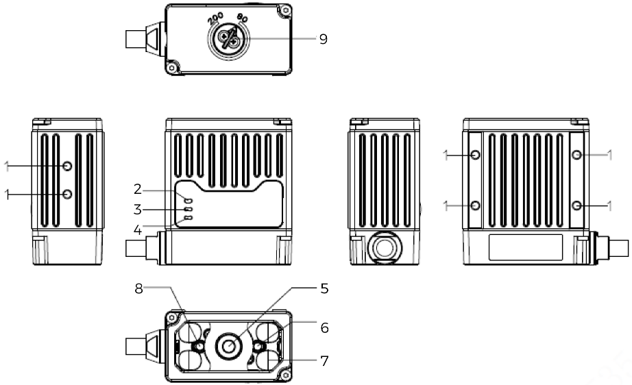
AIC-Lite-016M-07M-W-GL and AIC-Lite-016M-16M-W-GL
|
|
|
|
No. |
Name |
Function |
|---|---|---|
① |
Mounting hole |
Used to secure the camera, you can use the M3 screws provided in the box. |
② |
LINK indicator |
Network connection indicator Green solid on: network normal |
③ |
POWER indicator |
Power indicator Solid on: power normal Off: power abnormal |
④ |
OK/NG indicator |
Green: image captured successfully. |
⑤ |
Image sensor |
Used to capture image data. |
⑥ |
Orange dot indicator |
Can be turned on manually, used to assist in locating the workpiece under inspection. |
⑦ |
Fill light |
LED light source, provides fill lighting during image acquisition to ensure imaging quality. White light on the upper and lower sides, each can be set to high-frequency strobe, strobe or off. |
⑧ |
Green dot indicator |
Can be turned on manually, used to assist in locating the workpiece under inspection. |
⑨ |
Focus adjustment nut |
Adjust the focal length with the focus wrench to obtain clear images, ensuring image acquisition quality. |
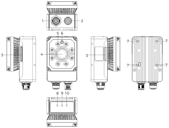
AIC-Lite-050M-08A-W-GL and AIC-Lite-050M-16A-W-GL
No. |
Name |
Function |
|---|---|---|
① |
Network interface |
Gigabit Ethernet interface, M12-A female socket, 8 pins. |
② |
Power and I/O interface |
Integrated power and trigger I/O, M12-A aviation male plug, 12 pins. |
③ |
Side indicator light |
Solid on: image captured successfully |
④ |
Image sensor |
Used to capture image data. |
⑤ |
Fill light |
LED light source, provides fill lighting during image acquisition to ensure imaging quality. Four independent channels, each can be set to steady on, strobe or off. |
⑥ |
Aimer |
Used for positioning. |
⑦ |
Mounting hole |
Used to secure the camera, you can use the M3 screws provided in the box. |
⑧ |
POWER indicator |
Power indicator Solid on: power normal Off: power abnormal |
⑨ |
LINK indicator |
Network connection indicator Solid on: network connection normal Flashing: data being transmitted Off: network connection abnormal |
⑩ |
STATUS indicator |
Solid on: the image sensor is in a triggered state and is acquiring image data Off: the camera is not currently acquiring data |
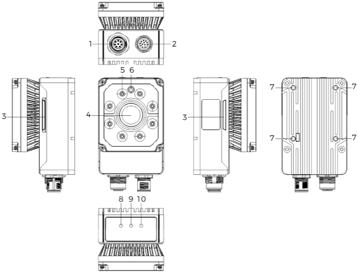
AIC-Lite-050C-08A-W-GL
No. |
Name |
Function |
|---|---|---|
① |
Network interface |
Gigabit Ethernet interface, M12-A female socket, 8 pins. |
② |
Power and I/O interface |
Integrated power and trigger I/O, M12-A aviation male plug, 12 pins. |
③ |
OK/NG indicator |
Green: image captured successfully. |
④ |
Image sensor |
Used to capture image data. |
⑤ |
Fill light |
Polarized/non-polarized fill light, supports turning on or off. |
⑥ |
Aimer |
Used for positioning. |
⑦ |
Mounting hole |
Used to secure the camera, you can use the M3 screws provided in the box. |
⑧ |
POWER indicator |
Power indicator Solid on: power normal Off: power abnormal |
⑨ |
LINK indicator |
Network connection indicator Solid on: network connection normal Flashing: data being transmitted Off: network connection abnormal |
⑩ |
STATUS indicator |
Solid on: the image sensor is in a triggered state and is acquiring image data Off: the camera is not currently acquiring data |
AIC-Lite-120M-00C-N-GL, AIC-Lite-200M-00C-N-GL, and AIC-Lite-250M-00C-N-GL
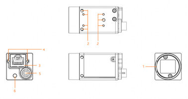
No. |
Name |
Function |
|---|---|---|
① |
Lens mount |
Used to install the lens. Please refer to the technical specifications to confirm the lens mount specifications for each model. |
② |
Mounting screw holes |
Used to secure the camera. Please refer to the technical specifications to confirm the mounting hole positions and applicable screw specifications for each model. |
③ |
Network interface |
Gigabit Ethernet interface, RJ45 port, used for data transmission. |
④ |
Ethernet port locking screw hole (M2) |
Used to secure the network cable connected to the camera, to avoid image acquisition anomalies caused by a loose connector. |
⑤ |
Power and I/O interface |
Integrates power, trigger I/O and serial communication, M6 connector, 6 pins. |
⑥ |
Indicator lights |
Used to display the camera operating status, please see the table below for details. |
Status |
Indicator status |
Description |
|
|---|---|---|---|
Normal status |
Red |
Red light fast flashing |
Device starting up. |
Blue |
Blue light low brightness |
IP assigned, application software API not connected to the device. |
|
Red and blue high brightness |
Application software API connected to the device, free mode, no image transmission. |
||
Blue light fast flashing |
Application software API connected to the device, free mode, image transmission active. |
||
Blue light slow flashing |
Trigger mode in use. |
||
Red/Blue |
Red and blue flashing alternately |
Firmware upgrading. |
|
Abnormal status |
Red |
Red light solid on |
Device abnormal (e.g., no data stream, firmware upgrade failure, etc.). |
Red light slow flashing |
Network disconnected. |
||
Install the Camera
Mount through the Camera Bracket
-
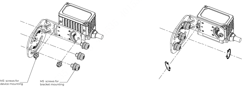
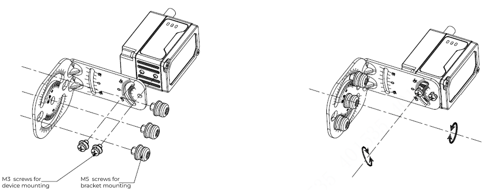
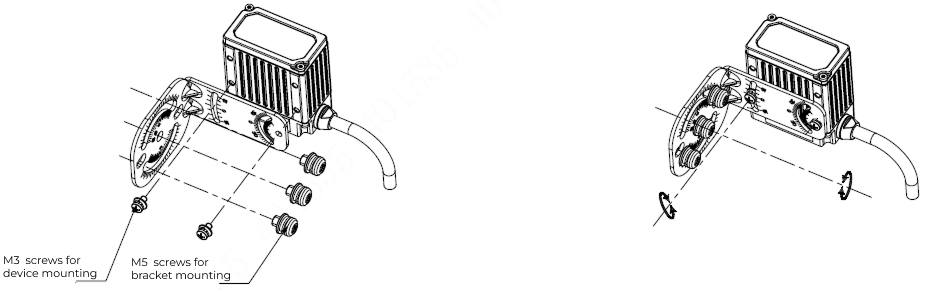
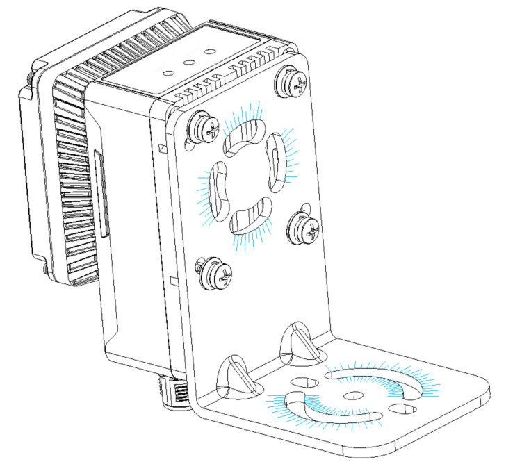
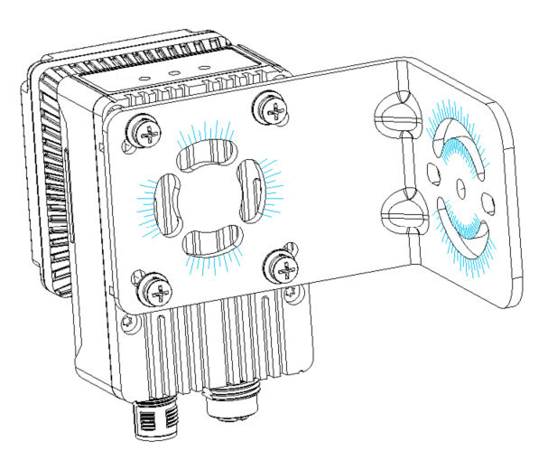
After confirming the mounting position, use M5 screws to fasten the mounting bracket to the mounting surface.
-
Insert screws of the corresponding specification into the mounting holes and tighten them to secure the camera to the mounting bracket.
-
AIC-Lite-016M-07M-W-GL and AIC-Lite-016M-16M-W-GL: M3 Phillips countersunk screws
-
AIC-Lite-050M-08A-W-GL, AIC-Lite-050M-16A-W-GL, andAIC-Lite-050C-08A-W-GL: M4 Phillips countersunk screws
-
|
AIC-Lite-120M-00C-N-GL, AIC-Lite-200M-00C-N-GL, and AIC-Lite-250M-00C-N-GL do not include a mounting bracket. Design a mounting bracket yourself if needed. |
-
AIC-Lite-016M-07M-W-GL (rear mounting):
-
AIC-Lite-016M-07M-W-GL (side mounting):
-
AIC-Lite-016M-16M-W-GL (rear mounting):
-
AIC-Lite-016M-16M-W-GL (side mounting):
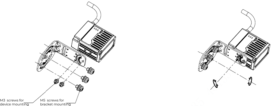
-
AIC-Lite-050M-08A-W-GL, AIC-Lite-050M-16A-W-GL, and AIC-Lite-050C-08A-W-GL (rear mounting):
Mounting through Camera Threaded Holes
-
Open the camera’s lens cap or dust cap, and install a lens of the appropriate specification. If the lens mount is incompatible, use a corresponding lens adapter ring. AIC-Lite-016M-07M-W-GL, AIC-Lite-016M-16M-W-GL, AIC-Lite-050M-08A-W-GL, AIC-Lite-050M-16A-W-GL, and AIC-Lite-050C-08A-W-GL do not require a lens.
-
Insert screws of the corresponding specification into the mounting holes and tighten them to secure the camera to the mounting surface.
-
AIC-Lite-016M-07M-W-GL, AIC-Lite-016M-16M-W-GL, AIC-Lite-120M-00C-N-GL, AIC-Lite-200M-00C-N-GL, and AIC-Lite-250M-00C-N-GL: M3 Phillips countersunk screws
-
AIC-Lite-050M-08A-W-GL, AIC-Lite-050M-16A-W-GL, and AIC-Lite-050C-08A-W-GL: M4 Phillips countersunk screws
-
Connect Cables
AIC-Lite-016M-07M-W-GL, AIC-Lite-016M-16M-W-GL, AIC-Lite-050M-08A-W-GL, AIC-Lite-050M-16A-W-GL and AIC-Lite-050C-08A-W-GL
Opto-Isolated Input
Opto-isolated inputs support sensors with NPN/PNP/push-pull output structures.
Sensors with NPN Output
-
Method 1: No pull-up resistor added (recommended).
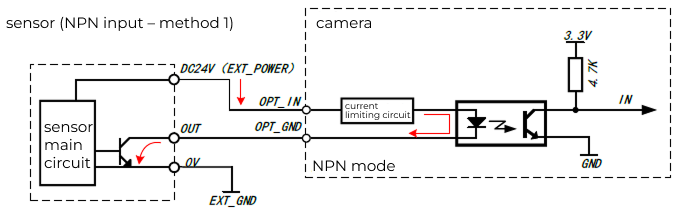
-
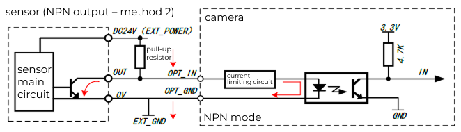
Method 2: Add a pull-up resistor.
-
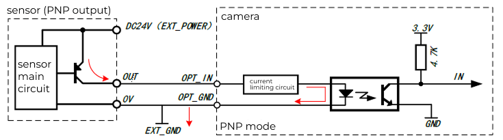
EXT_POWER refers to the positive terminal of the user’s external power supply, and EXT_GND refers to the ground of the user’s external power supply. The external power supply can be a standalone switching power supply or the sensor’s power supply.
-
This wiring method applies to sensors with NPN open-collector output structure.
-
Recommended pull-up resistor values: 1kΩ at 3.3V supply,1kΩ at 5V supply,2.4kΩ at 12V supply, 4.7kΩ at 24V supply. If higher output current capability is required, you may choose a resistor less than 1kΩ, but its rated power should be higher than 1W.
-
In some models, OPT_IN_GND and OPT_OUT_GND are shared, named OPT_GND.
-
Opto-Isolated Output
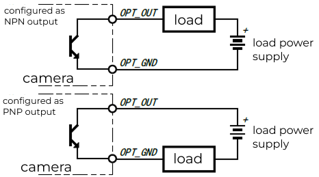
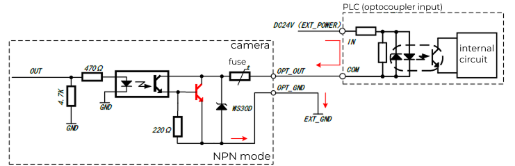
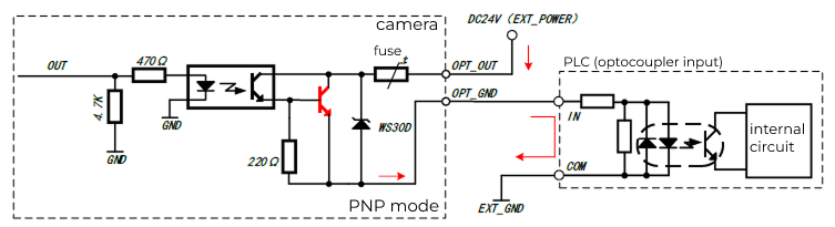
The camera’s transistor output is isolated from the internal circuitry by an optocoupler, so the transistor output can be used as NPN output or PNP output.
GPIO
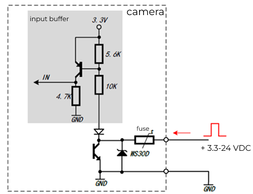
GPIO as Output
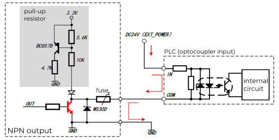
When GPIO is used as an output, its operation is similar to the opto-isolated output. However, GPIO uses non-isolated wiring, and the GPIO signal ground is common with the camera power ground.
|
Wiring Method for Inductive Loads Such as Relays
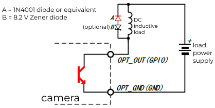
When using the camera output to drive inductive loads (such as relays), you must use relays with built-in flyback diodes or add an external flyback diode; otherwise, the output interface may be damaged by overvoltage.
The figure below shows an example of a DC inductive load suppression circuit. In most applications, using only the additional diode A is sufficient; if the application requires faster turn-off, it is recommended to also add the Zener diode B.Please ensure the selected Zener diode meets the current requirements of the output circuit.
AIC-Lite-120M-00C-N-GL, AIC-Lite-200M-00C-N-GL, and AIC-Lite-250M-00C-N-GL
Opto-Isolated Input
Sensors with NPN Output
-
Method 1: Add a pull-up resistor.
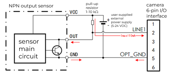
With this connection, the camera’s opto-isolated input LINE1 and opto-isolated output LINE0 can both be used.The schematic for connecting an NPN-output sensor to the opto-isolated input is shown below.
-
Recommended pull-up resistance: 1 to 10kΩ. In general,1kΩ at 5V supply, 2.4kΩ at 12V supply, 4.7kΩ at 24V supply.
-
The camera’s LINE1 input logic state is opposite to the sensor output state. When the sensor output is "ON", the internal transistor of the sensor is conducting, OUT and GND are shorted, LINE1 input is low level, corresponding to logic value "0"; when the sensor output is "OFF", the transistor is cut off, OUT is pulled to the external power supply voltage through the external pull-up resistor, LINE1 input is high level, corresponding to logic value "1".
-
The red arrows indicate the current direction (same below).
-
-
Method 2: No pull-up resistor added.
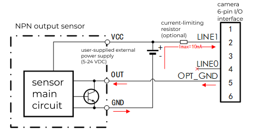
With this connection, only the camera’s opto-isolated input LINE1 is available, the opto-isolated output LINE0 is not available. The schematic for connecting an NPN-output sensor to the opto-isolated input is shown below.
-
In general, no series current-limiting resistor is required. When the external power supply is 24V and the supply voltage is unstable, it is recommended to insert a 1kΩ resistor in series at the LINE1 input to avoid overvoltage in the input circuit and damaging the camera.
-
The camera’s LINE1 input logic state matches the sensor output state. When the sensor output is "ON", the sensor’s internal transistor conducts, OUT and GND are shorted, external supply current flows through the current-limiting resistor (optional) into LINE1, then through the camera’s internal optocoupler input circuit, flows out from OPT_GND, and finally returns to the external power ground GND through the sensor’s internal transistor.
-
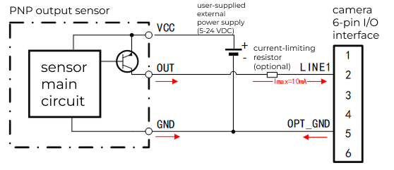
Sensors with PNP Output
|
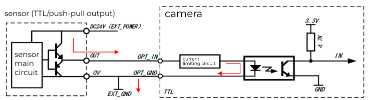
Sensors with TTL Output
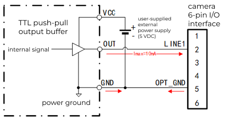
With this connection, the camera’s opto-isolated input LINE1 and opto-isolated output LINE0 can both be used.The schematic for connecting a TTL circuit output to the opto-isolated input is shown below.
|
The TTL circuit can be a frame grabber or a sensor with complementary push-pull output. |
Application Examples of Connecting the Camera to a PLC
In transistor-type PLC output circuits, the I/O that sources current to the outside is called source (Source) output, and the I/O that sinks current is called sink (Sink) output.Sink outputs typically use NPN transistors, while source outputs typically use PNP or NPN transistors.Multiple PLC outputs share the same common terminal (COM), the common terminal of sink outputs connects to power ground (0V), and the common terminal of source outputs connects to the power supply (VCC).
-
Connecting a PLC with sink (common collector) output
-
Method 1: No pull-up resistor added.
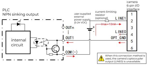
With this connection, only the camera’s opto-isolated input LINE1 is available,the opto-isolated output LINE0 is not available.The schematic for connecting the opto input to a PLC with sink output is shown below.
-
In the PLC-side output circuit shown above, Omron CP1E-E10 PLC is used as an example, where COM is the common terminal and OUT1 to OUTn are output terminals sharing the same common terminal.
-
With this connection, the camera’s opto-isolated output LINE0 is not available.
-
In general, no series current-limiting resistor is required. When the external power supply is 24V and the supply voltage is unstable, it is recommended to insert a 1kΩ resistor in series at the LINE1 input to avoid overvoltage in the input circuit and damaging the camera.
-
-
Method 2: Add a pull-up resistor.
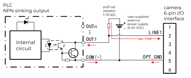
With this connection, the camera’s opto-isolated input LINE1 and opto-isolated output LINE0 can both be used.The schematic for connecting the opto input to a PLC with sink output is shown below.
-
In the PLC-side output circuit shown above, Omron CP1E-E10 PLC is used as an example, where COM is the common terminal and OUT1 to OUTn are output terminals sharing the same common terminal.
-
Recommended pull-up resistance: 1 to 10kΩ. In general,1kΩ at 5V supply, 2.4kΩ at 12V supply, 4.7kΩ at 24V supply.
-
The camera’s input logic state is opposite to the PLC output state.
-
-
-
Connecting a PLC with source (common emitter) output
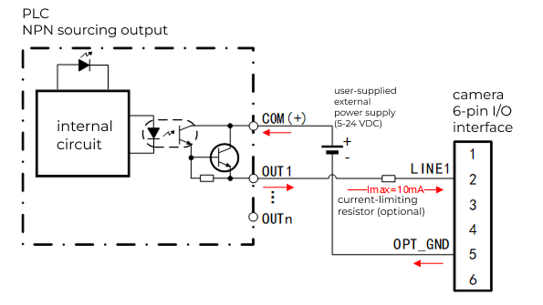
The schematic for connecting the opto input to a PLC with source output is shown below.
-
In the PLC-side output circuit shown above, Omron CP1E-E10 PLC is used as an example, where COM is the common terminal and OUT1 to OUTn are output terminals sharing the same common terminal.
-
In general, no series current-limiting resistor is required. When the external power supply is 24V and the supply voltage is unstable, it is recommended to insert a 1kΩ resistor in series at the LINE1 input to avoid overvoltage in the input circuit and damaging the camera.
-
The camera’s input logic state is the same as the PLC output state.
-
Opto-Isolated Output
Optocoupler as NPN Output Connecting Indicator Light and Buzzer
The schematic for connecting an indicator light with the optocoupler as an NPN output is shown below.
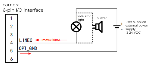
|
The red arrows indicate the current direction when the optocoupler output is conducting(logic "1")(same below). |
Optocoupler as NPN Output Connecting PLC Input
The schematic for connecting to PLC input with the optocoupler as an NPN output is shown below.
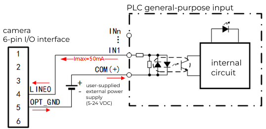
|
In the PLC-side output circuit shown above, Omron CP1E-E10 PLC is used as an example, where COM is the common terminal and IN1 to INn are input terminals sharing the same common terminal. |
Optocoupler as PNP Output Connecting PLC Input
The schematic for connecting to PLC input with the optocoupler as a PNP output is shown below.
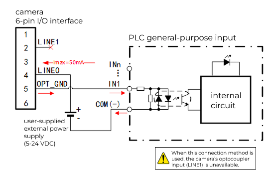
|
Optocoupler as NPN Output Connecting a Light Source Controller
Connecting a light source controller with the optocoupler as an NPN output is shown below.
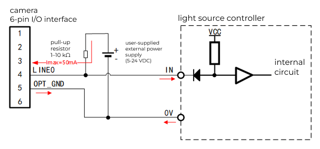
|
Pull-up resistor value: 1 to 10kΩ,recommended value: 3.3V. In general,1kΩ at 5V supply, 2.4kΩ at 12V supply, 4.7kΩ at 24V supply. If the light source controller has a built-in pull-up resistor, an external pull-up resistor is not required. |
GPIO
GPIO as Input
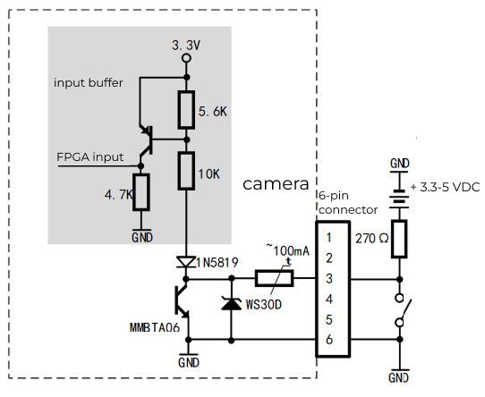
The schematic for connecting a mechanical switch with GPIO as input is shown below.
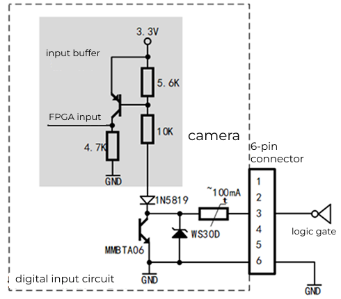
The schematic for connecting a 5V TTL logic output with GPIO as input is shown below.
GPIO as Output
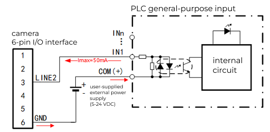
The schematic for connecting to PLC input with GPIO as output is shown below.
|
Download and Install Mech-Vision
You can download the Mech-Vision installer from the Mech-Mind Download Center.
Connect the Camera
In the Mech-Vision menu bar, select to open the 2D Camera Management tool, and then connect the camera by following the steps below.
-
Add the camera and establish a connection.
In the camera list area, click Add. You can add a 2D camera using one of the following methods.
-
Automatic search
The system automatically scans the current network and lists available cameras in the same subnet. This method is suitable for most standard deployment scenarios.
-
Search by IP address
You can manually enter a camera IP address to add the device.
After a camera is added, it is connected by default. You can disconnect, rename, and delete cameras in the camera list, and modify the IP address or upgrade firmware in the camera information area.
You can modify the camera name only when the camera is connected. You can modify the camera IP address and upgrade firmware only when the camera is disconnected. -
-
Configure the camera IP address.
If this is the first time you connect the camera, or if the camera and the IPC are not in the same subnet, modify the camera IP address first.
Get the current IP settings of the IPC network adapter and confirm the target subnet. Then click "Modify IP address"
 in the camera information area, and select a configuration method based on the on-site network environment.
-
Manual
Select "Manual" and manually enter the IP address, Subnet mask, and Default gateway.
-
Automatic (DHCP)
Select "Automatic (DHCP)" and the DHCP server automatically assigns network parameters. In this mode, the IP address, subnet mask, and default gateway are obtained automatically.
After saving the configuration, reconnect the camera and confirm that the connection status is normal. We recommend setting a unique IP address for each camera to avoid address conflicts in the same subnet.
-
Check Image Acquisition Quality
In the lower-right corner of the 2D Camera Management tool, click Continuous Acquisition to capture images and check image acquisition quality.
Adjust Parameters
After capturing images, confirm that image brightness, clarity, and orientation are correct. If the results are not as expected, adjust parameters such as Exposure time and Gain. For detailed parameter descriptions, see Camera Parameters.
Save and Use Data
After image acquisition quality meets expectations, you can use the 2D Smart Camera Step in Mech-Vision to acquire images and perform image preprocessing and postprocessing.
|
To save image data, enable Data Storage in Mech-Vision. |