Example program 3: Sample_3
Program Introduction
Description |
The robot triggers the Mech-Vision project to run, and then obtains the planned path for picking and placing. |
File path |
Mech-Vision and Mech-Viz are located in This file contains three subprograms: Sample_1, Sample_2, and Sample_3. This section only introduces the Sample_3 subprogram. |
Project |
Mech-Vision project |
Prerequisites |
|
| This example program is provided for reference only. Before using the program, please modify the program according to the actual scenario. |
Program Description
This part provides and explains the code of the Sample_3 example program.
Sub Sample_3
'-------------------------------
'FUNCTION:simple pick and place
'with Mech-Vision
'Mech-Mind, 2022-8-4
'-------------------------------
'Getting control of the robot.
TakeArm Keep = 0
'move to the home position
Move P, P[1],speed=80
'move to the camera position
Move P,@C P[2],speed=80
Open_socket
'set vision recipe
MM_Set_Model 1,1
Delay 100
'Run vision project
MM_Start_Vis 1,0,1,2
Delay 100
'get planned path from Mech-Vision Path Planning Step
MM_Get_VisPath 1,2,1,2,3
IF I[3]<>1103 THEN
stop
END IF
'set the first pos to P20
'set lables to I11
'set speed to I12
MM_Get_Pose 1,20,11,12
'set the second pos to P21
'set lables to I13
'set speed to I14
MM_Get_Pose 2,21,13,14
''set the third pos to P22
'set lables to I15
'set speed to I16
MM_Get_Pose 3,22,15,16
Move P, P[20],speed=80
Move L,@C P[21],speed=80
'enable girpper
Set IO[24]
Move P, P[22],speed=80
Move P, P[3],speed=80
'drop point
Move L,@C P[4],speed=80
'release gripper
Reset IO[24]
'Giving up control of the robot
GiveArm
Close_socket
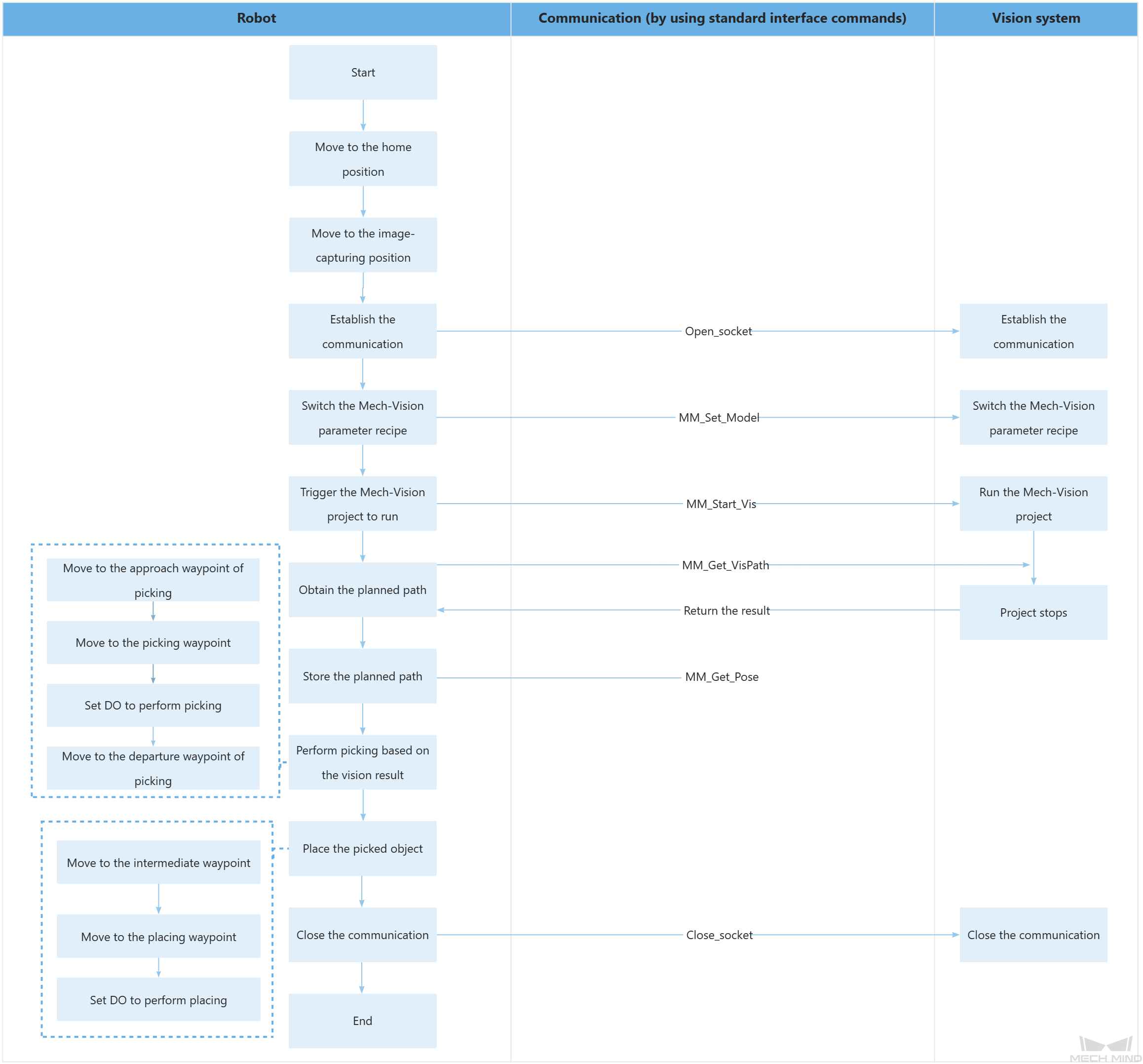
End SubThe workflow corresponding to the above example program code is shown in the figure below.
The table below explains the above program. You can click the hyperlink to the command name to view its detailed description.
| Feature | Code and description | ||
|---|---|---|---|
Obtain the control |
TakeArm Keep = 0 Obtain the control of the robot arm group and perform the following initialization operations:
|
||
Move to the home position |
The robot moves from the current position to the home position (P[1]) at 80% of its velocity. The P parameter indicates the point-to point movement.
|
||
Move to the image-capturing position |
The robot moves from its current position to the image-capturing position (P[2]) at 80% of its velocity. @C indicates that the robot will execute the next command when it confirms that the transformed position and pose of the forearm have reached the desired objectives based on the encoded value.
|
||
Establish the communication |
The robot establishes TCP communication with the vision system through the Open_socket command. |
||
Switch the Mech-Vision parameter recipe |
In this entire statement, the parameter recipe of the Mech-Vision project whose ID is 1 is switched to recipe 1.
Delay indicates that the task will be put on standby within the specified delay time. The delay time is measured in milliseconds (ms). The preceding statement indicates that the robot is on standby for 100 ms to ensure that the Mech-Vision has enough time to switch the parameter recipe. |
||
Trigger the Mech-Vision project to run |
The entire statement indicates that the robot triggers the vision system to run the Mech-Vision project with an ID of 1 and expects the Mech-Vision project to return all waypoints. The above statement indicates that the robot is on standby for 100 ms to ensure that the camera has enough time to capture images. |
||
Get the planned path |
The entire statement indicates that the robot obtains the planned path from the Mech-Vision project that has an ID of 1.
When the status code is 1103 in I[3], the robot has successfully obtained all planned path. Otherwise, an error may be returned in the vision system. You can perform the corresponding operation based on the specific exception code. |
||
Store the planned path |
The entire statement stores the TCP pose, label, and velocity of the first waypoint in P[20], I[11], and I[12]. The above code stores the TCP pose, label, and velocity of the second waypoint in P[21], I[13], and I[14], respectively, and the TCP pose, label, and velocity of the third waypoint in P[22], I[15], and I[16], respectively. |
||
Move to the approach waypoint of picking |
The robot moves to the approach waypoint of picking (P[20]) in point-to-point mode.
|
||
Move to the picking waypoint |
The robot moves from the approach waypoint of picking to the picking waypoint (P[21]) in linear motion. |
||
Set DO to perform picking |
Set IO[24] After the robot moves to the picking waypoint, you can set a DO (such as Set IO[24]) to control the robot to use the tool to perform picking. Please add the operation of setting DOs according to the actual situation. |
||
Move to the departure waypoint of picking |
The robot moves to the departure waypoint of picking (P[22]) in point-to-point mode.
|
||
Move to the intermediate waypoint |
The robot moves to a intermediate waypoint between the departure waypoint of picking and the placing waypoint (P[3]).
|
||
Move to the placing waypoint |
The robot moves from the intermediate waypoint to the placing waypoint (P[4]).
|
||
Set DO to perform placing |
Reset IO[24] After the robot moves to the placing waypoint, you can set a DO (such as Reset IO[24]) to control the robot to use the tool to perform placing. Please add the operation of setting DOs according to the actual situation. |
||
Release the control |
Release the control on the robot arm group. |
||
Close the communication |
The TCP communication between the robot and the vision system is closed by using the Close_socket command. |