[3D Measurement and Inspection] Train a Terminal Comprehensive Inspection Model
This topic takes the terminal comprehensive inspection project as an example (click to download the example project) to introduce how to use tree-structured algorithm modules to train a model.
Scenario Description
In the terminal comprehensive inspection task, it is usually necessary to detect defects on different parts of a connector. However, the defect types and features vary across different parts. If a single Defect Segmentation model is trained for all parts, it is often difficult to balance the detection accuracy across all parts. This example adopts a “classification first, then segmentation” workflow: the Classification module is first used to identify the connector part in each image, and then Defect Segmentation modules are trained separately for different parts to improve overall defect detection performance. The typical defects involved in this example include housing scratches, latch deformation, shielding shell scratches, and terminal deformation.
Module Combination
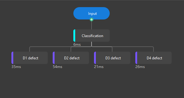
As shown in the figure below, the construction of a terminal comprehensive inspection model mainly consists of two kinds of modules: Classification and Defect Segmentation.
-
Classification: Initially filters images and determines which part (such as the housing, latch, shielding shell, or terminal) of the connector each image corresponds to for subsequent module detection.
In this example, the Classification module has four classes, namely, D1, D2, D3, and D4, which correspond to the connector housing, latch, shielding shell, and terminal.
-
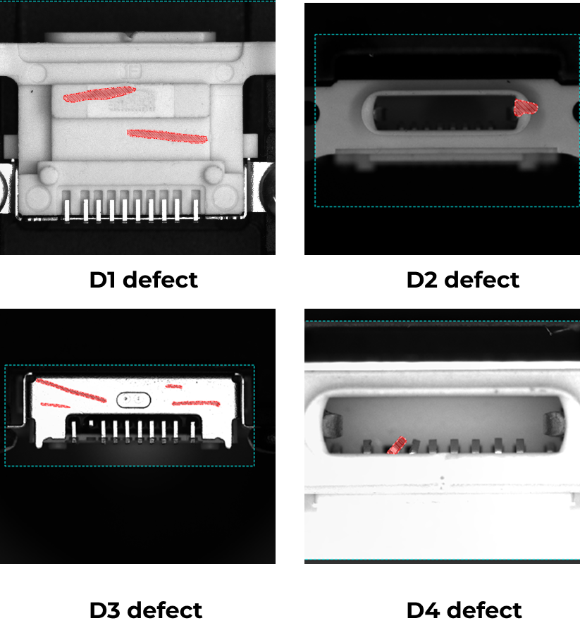
Defect Segmentation: Different Defect Segmentation modules are used to accurately detect and segment defects at different parts of the connector, and recognize specific problems such as scratches and deformations.
In this example, D1 defect is used to detect scratches on the housing, D2 defect is used to detect deformation of the latch, D3 defect is used to detect scratches on the shielding shell, and D4 defect is used to detect deformation of the terminal.
|
In applications, module combinations should be flexibly adjusted and optimized according to specific requirements. The flexibility of tree-structured algorithm modules allows modules to be freely combined and configured according to different inspection requirements for optimal detection performance. |
Usage Workflow
According to the above requirements, after constructing the tree-structured algorithm modules, you need to label, train, and validate each module separately before verifying the overall effect. Follow the steps below:
-
Classification: Perform the following operations on the Classification module in sequence. After confirming that the classification results meet the requirements, proceed with the labeling, training, and validation of the subsequent Defect Segmentation modules.
-
Label image data: Label the part to which each image belongs (D1: housing, D2: latch, D3: shielding shell, D4: terminal).
-
Train the model: Set training parameters as required and train the model.
-
Validate the model: Use the trained model to validate the data and evaluate whether the classification accuracy meets the requirements.
-
-
Defect Segmentation Modules: For the four Defect Segmentation modules (D1 to D4), complete the following operations.
-
Label image data: Label defect regions according to the images of corresponding parts.
-
Train the model: Set training parameters as required and train the model.
-
Validate the model: Use the trained model to validate the data and evaluate whether the defect detection accuracy meets the requirements.
-
-
Validate overall performance: After all modules pass validation, you can import real-world image data in Operation Mode, perform overall inference according to the set validation rules, and output validation results to quickly evaluate the model’s overall performance in real scenarios. Images with poor results can be directly added to corresponding modules for further training until the expected performance is achieved.