Advanced: Using the Mask Tool to Exclude Training Interference
For image data with interfering elements, you can use the mask tool in Mech-DLK to cover them and eliminate potential interference during training, thereby improving training accuracy. This section explains how to use the mask tool correctly, covering application scenarios, mask types, mask modes, and usage tips.
Application Scenarios
-
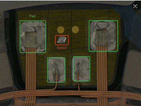
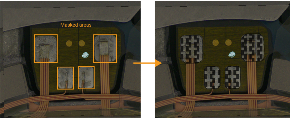
Target areas and some non-target areas have highly similar characteristics: For example, in the defect segmentation case shown below, excess solder on non-pad areas is incorrectly identified as defects. The four solder pads on the pad and the excess solder defects have similar appearance and reflective characteristics, which may interfere with model training. Therefore, it is necessary to use the mask feature to cover the standard solder pads.
-
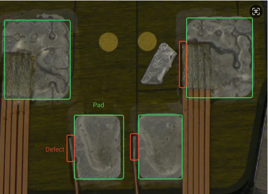
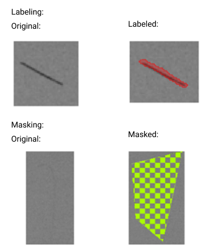
Target and non-target areas are close to each other or partially overlapping: For example, in the chip image defect segmentation case shown below, the exposed copper wire defect is very close to the solder pad, with overlapping contours between defect and non-defect areas. Therefore, it is recommended to use the mask tool to cover non-defect areas to ensure accurate model recognition.
Mask Types
You can choose among the following three mask tools built in Mech-DLK according to actual needs.
-
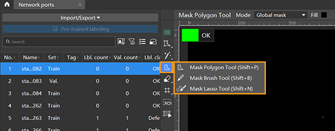
Mask polygon tool
Click multiple times to draw a polygon mask according to the shape of the area to be covered.
-
Click the Mask Polygon Tool icon
 (or press Shift + P on the keyboard).
 -
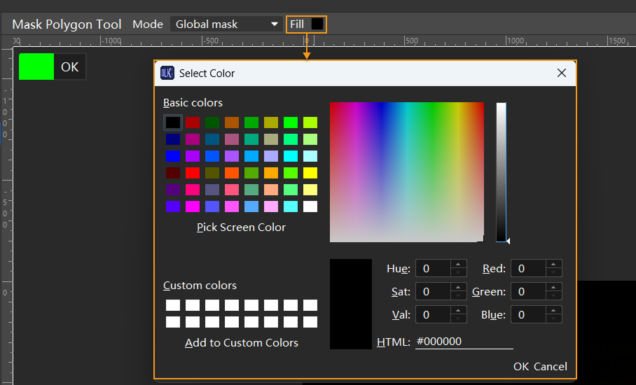
In the upper toolbar of the image display section, set Mode (applicable only to specific modules) and Fill.
-
In the labeling area, left-click multiple times at different positions (anchor points) according to the shape of the area to be covered. Once the mask covers the target area, right-click to complete the drawing.
-
-
Mask brush tool
Draw the mask by clicking and dragging according to the shape of the area to be covered.
-
Right-click the Mask Polygon Tool icon
, and then click the Mask Brush Tool icon  (or press Shift+B on the keyboard).
 -
In the upper toolbar of the image display section, set Mode (applicable only to specific modules), Fill, and the brash size.
-
In the labeling area, press and hold the left mouse button and drag in any direction. Once the mask covers the target area, release the left mouse button to complete the drawing.
-
-
Mask lasso tool
Click and drag along the edge of the area to be covered to draw the mask.
-
Right-click the Mask Polygon Tool icon
, and then click the Mask Lasso Tool icon  (or press Shift+N on the keyboard).
 -
In the upper toolbar of the image display section, set Mode (applicable only to specific modules) and Fill.
-
In the labeling area, press and hold the left mouse button and drag along the edge of the area to be covered. Once a closed shape is formed with the starting point, release the mouse button to complete the drawing.
-
-
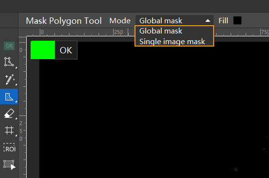
Mask mode
Mask modes are divided into Global mask and Single image mask. You can select it from the mask toolbar, as shown in the image below.
-
Single image mask: The mask is only valid in the current image. Copy and batch-paste single image masks by following these steps:
-
Use the Mask Tool to draw a single image mask.
-
Click the Select Tool icon
 (or press F on the keyboard).
 -
In the labeling region, right-click the mask to be copied and click Copy (or press Ctrl+C on the keyboard); in the target image, right-click and select Paste (or press Ctrl + V on the keyboard). You can also select multiple target images in the image list, right-click and select Paste Mask(s) to paste them in batches.
-
-
Global mask: The mask applies to all images.
-
Usage Tips
-
Choose the appropriate mask tool and mode.
Select the appropriate mask tool based on your actual situation. You should choose the mask tool according to the contour, size, shape, and other characteristics of the area to be covered. For example, in the defect segmentation case below, where the area to be covered has clear contours and regular shapes, it is recommended to use the Mask Polygon Tool to draw the mask, as shown in the image.
-
Choose the appropriate mask mode based on the possible locations of the area to be covered.
-
Global mask applies to all imported images. If the area to be covered is in the same position across all imported images, it is recommended to use the global mask. In the above defect detection case, the solder pads are areas that may interfere with training and are located in the same position in all images; therefore, using a global mask to cover them is recommended. After selecting the appropriate mask tool, you can choose Global Mask from the Mode drop-down list. Once the mask is drawn on any image, it will automatically apply to all imported images.
-
Single image mask only applies to the current image. If the areas to be covered vary in position across images, it is recommended to use the single image mask and draw masks individually on each image according to actual needs.
-
-
Correctly draw the mask area.
-
When drawing the mask, ensure that it fully covers the non-defect areas to avoid affecting model training.
-
When drawing the mask, the masked area does not need to be precisely outlined. When labeling, the labeling contour should closely follow the edges of the target area to avoid missing parts or including irrelevant areas. The masked area does not need to be precisely outlined.
-
When drawing the mask, try to ensure that the mask does not overlap with the labeled area. Areas where the mask overlaps with the labeling will not be included in training.
-
It is recommended to use the fill feature to draw masks in colors different from the labeled areas. You can click the color block next to Fill at the top of the image labeling section and select the mask color in the pop-up dialog.
-