Use the Defect Segmentation Module
This section provides pad image data from Mech-DLK (click to download) and guides you through training a model using the Defect Segmentation module. This section will guide you through labeling defects, adjusting parameter settings, and training, validating, and iterating the model to efficiently train a Defect Segmentation model with a small amount of data, aiming to achieve the detection of excess solder and exposed copper wire defects as shown in the sample project.
| You can also use your own data. Except for differences in the labeling stage, the overall usage process is the same. |
Preparations
If you use your own prepared data, please collect the required images according to the Data Acquisition Standard before importing the image data. Please ensure that all defects in the collected images are clearly visible; otherwise, the model training performance may be affected.
-
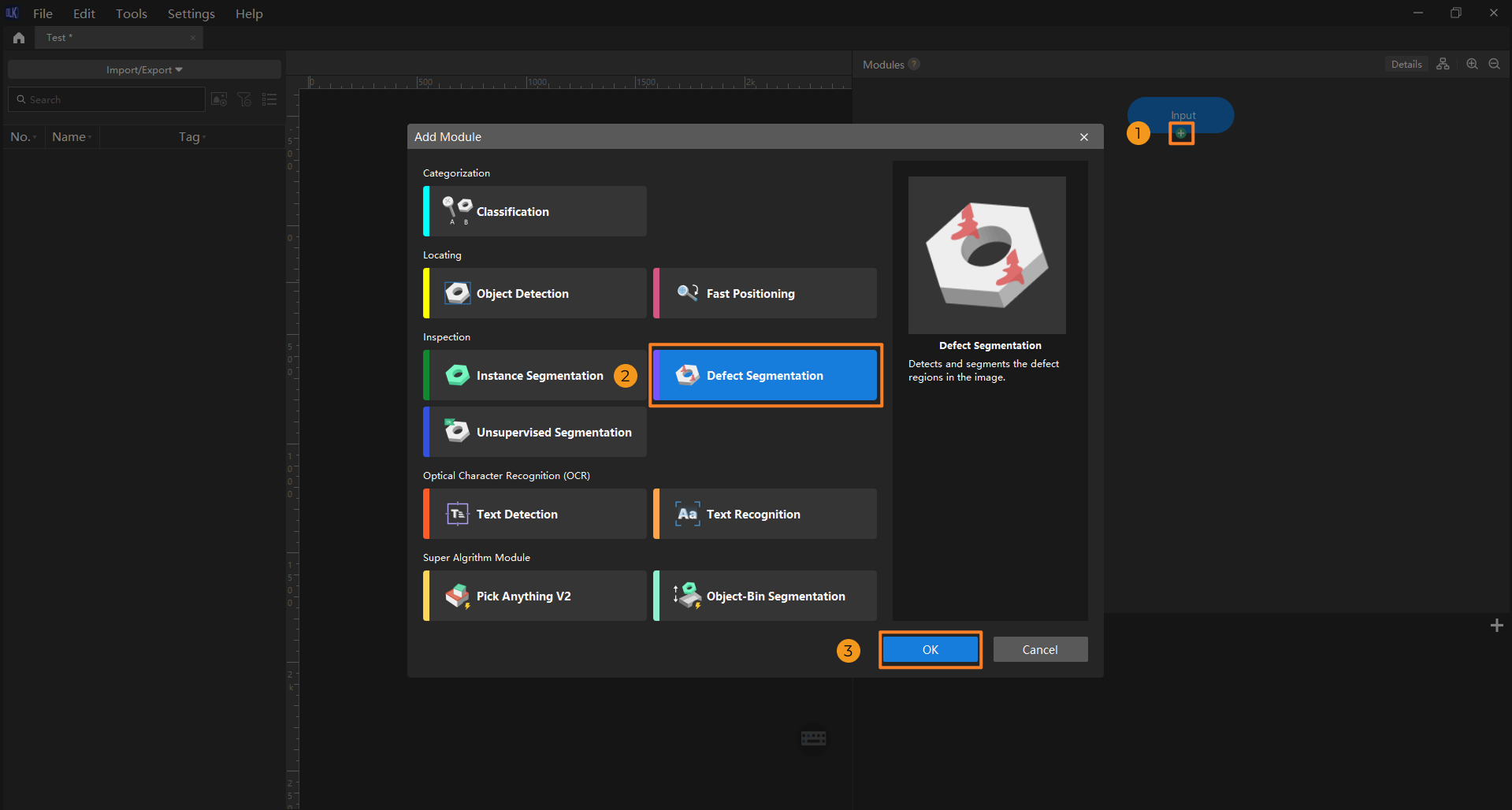
Create a new project and add the Defect Segmentation module: Open Mech-DLK, click New Project in the interface, name the project, and select a directory to save the project. In the main interface, click the + button under the Input module, and select the Defect Segmentation module in the Add Module window.
-
Import image data: Import the acquired image data or decompress the data file provided in this article. The image data should include cases of excess solder on pads, exposed copper wires, and defect-free conditions. You can use one of the following methods to import image data:
-
Method one
Drag and drop images or files into the image list area to import them. Importing datasets by dragging is not supported.
-
Method two
On the top of the image list, click the Import/Export button. Select the import method based on the data type:
-
Import from Previous Module: Import images from the previous module.
-
Import Images: Import one or more images.
-
Import Folder: Import all images in the folder (images in the subfolders are not included).
-
Import Dataset: Import datasets in the DLKDB format (.dlkdb), which are datasets exported from Mech-DLK.
-
-
-
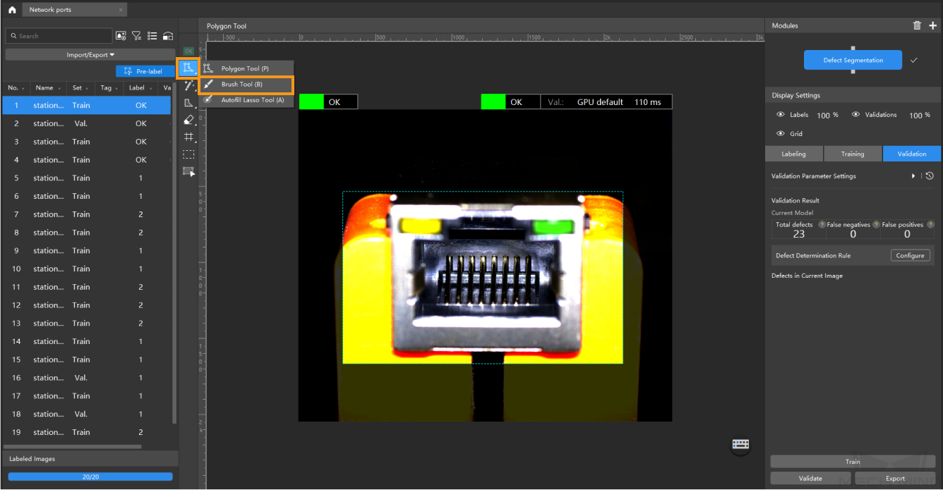
Crop ROI: If the defect locations in each image are close, you can use the ROI tool to draw regions of interest for model training. Setting the ROI can reduce interference from irrelevant background information. In this sample project, defects all appear at the pad locations. Therefore, you can click
 in the labeling toolbar to adjust the ROI and then click
  . The ROI setting will be applied to all images.
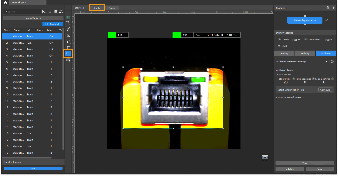
-
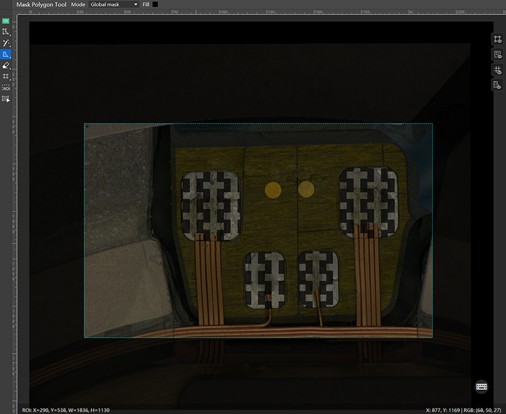
Use the mask tool to exclude training interference (optional): If defect and non-defect areas have similar characteristics or are overlapping, you can use a mask tool to cover parts that may interfere with model training. Excess solder defects and the surrounding four solder pads look very similar and are all reflective. Since the pad positions are generally consistent across the collected images, you can use a global mask to cover the standard solder pads, as shown in the image below.
-
Before using the ROI or global mask tool, please ensure that the object positions are consistent across the imported images; otherwise, the global mask may cover different actual areas in different images, affecting model training. If the object positions vary significantly across images, you can use tree-structured algorithm modules for adjustment. You can first use the Object Detection or Fast Positioning module to locate the object positions or align the images consistently, and then connect the Defect Segmentation module in series to train the model.
-
When using the masking feature, ensure that the mask fully covers the non-defect areas.
-
For more tips on using the masking tool, see Advanced: Using the Masking Tool to Exclude Training Interference.
-
Data Labeling
-
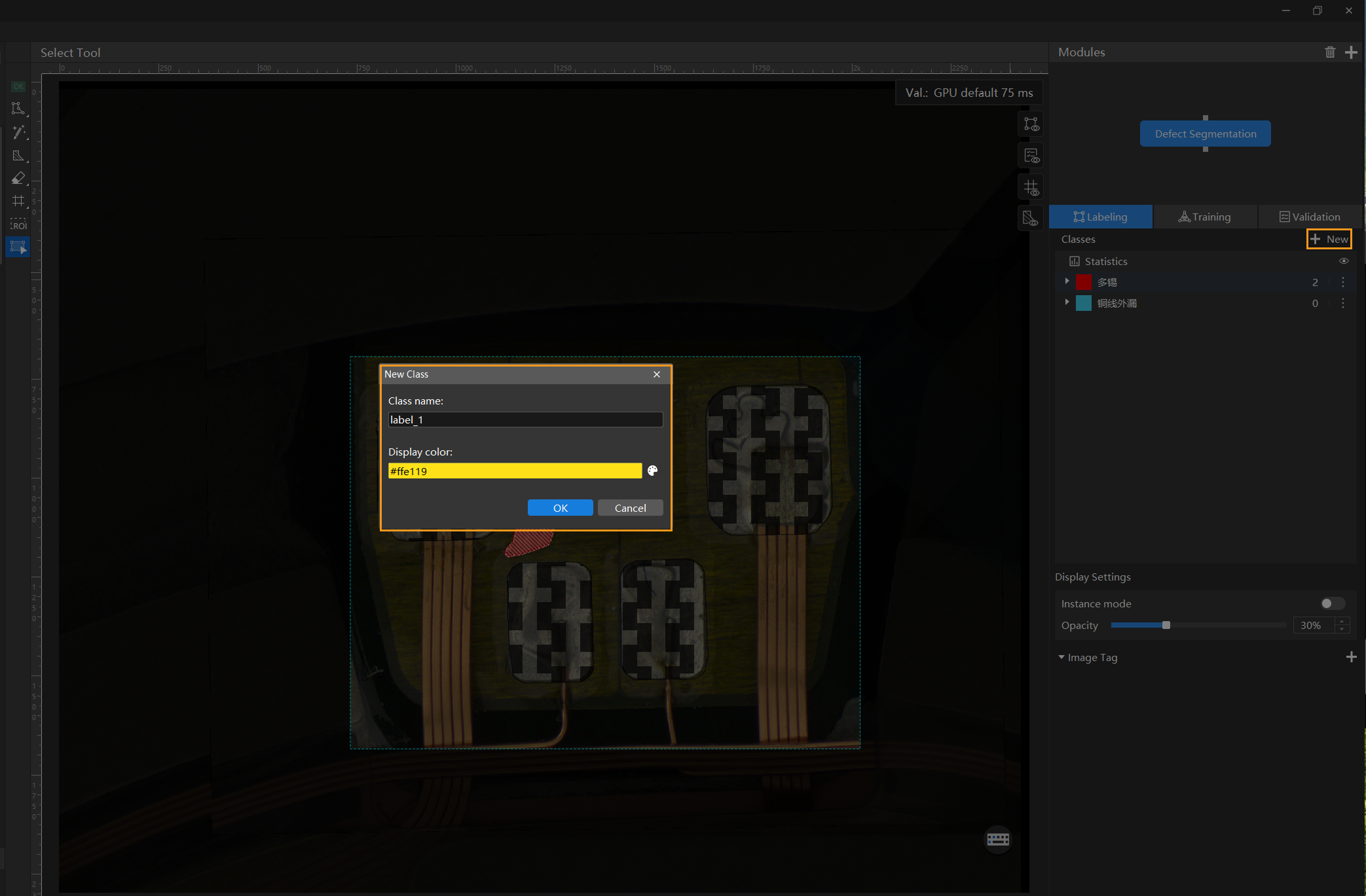
Create classes: Multiple classes are supported for labeling. You can create classes based on defect types and label accordingly.
-
Select a small amount of data for labeling: Model training does not require labeling all data. Precise and minimal labeling helps reduce manual labeling workload, improving label quality and speeding up training and validation. It also aids in identifying potential issues during model training and validation, reducing the time cost associated with adjusting training parameters. For example, in this sample project, you can select 5 images from the imported dataset for labeling.
-
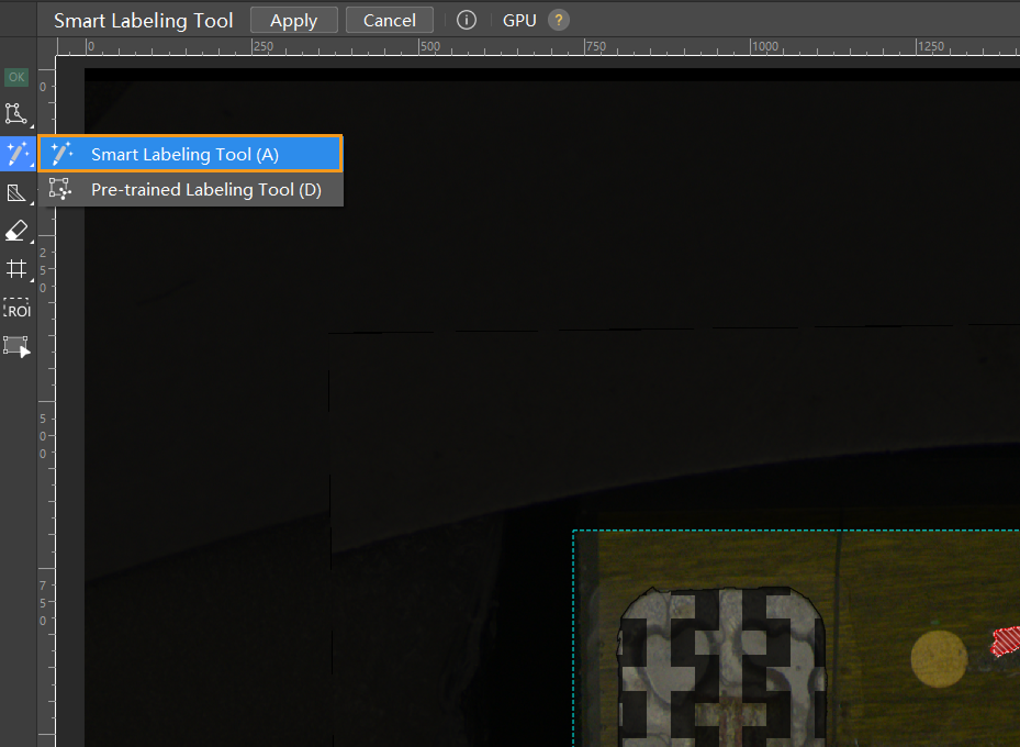
Use appropriate labeling tools: In this project, the defects have distinct characteristics and clear contours, so the smart labeling tool is recommended.
-
Label defects with significant differences: Please strictly follow the Data Labeling Standard to ensure labeling quality and avoid negatively impacting model training. Avoid repeatedly labeling images with highly similar defect characteristics. Instead, choose images with clearly different defect characteristics—such as variations in position, quantity, area, shape, color, or contour—for labeling. When labeling, make sure to follow the edges of the defect closely, and avoid extending the label beyond the defect area. If using the masking feature, avoid overlapping the mask area with the labeled area.
-
For example, in the two images below, the defect positions and shapes are similar, with only slight differences in defect brightness. To improve training efficiency and reduce manual labeling workload, labeling just one image is sufficient.
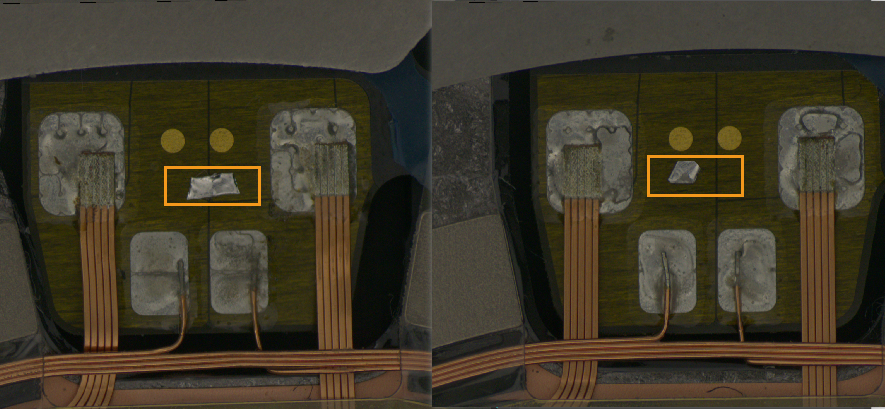
-
In the images below, the defects differ significantly (different defect quantities and locations), so both images need to be labeled.
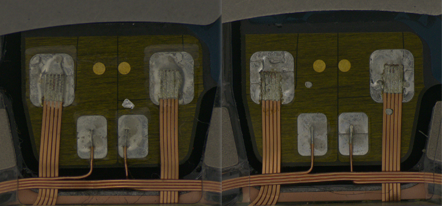
You can hold down the Ctrl key and scroll the mouse wheel up to zoom in on the image for more precise labeling.
-
-
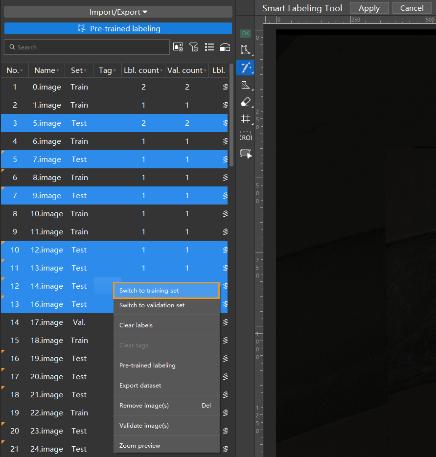
Add labeled images to the training set: After labeling is complete, select all labeled images and assign them to the training set to participate in model training. When training the model, it is recommended to use a small number of precisely labeled images as the training set to reduce the time cost of troubleshooting and adjusting training parameter settings.
-
Set at least one OK image (optional): Select a defect-free image, set it as an OK image, and move it to the training set. After selecting a defect-free image in the data list on the left, you can click
in the labeling toolbar or right-click the image and choose Set to OK, and then right-click the image again and select Switch to training set.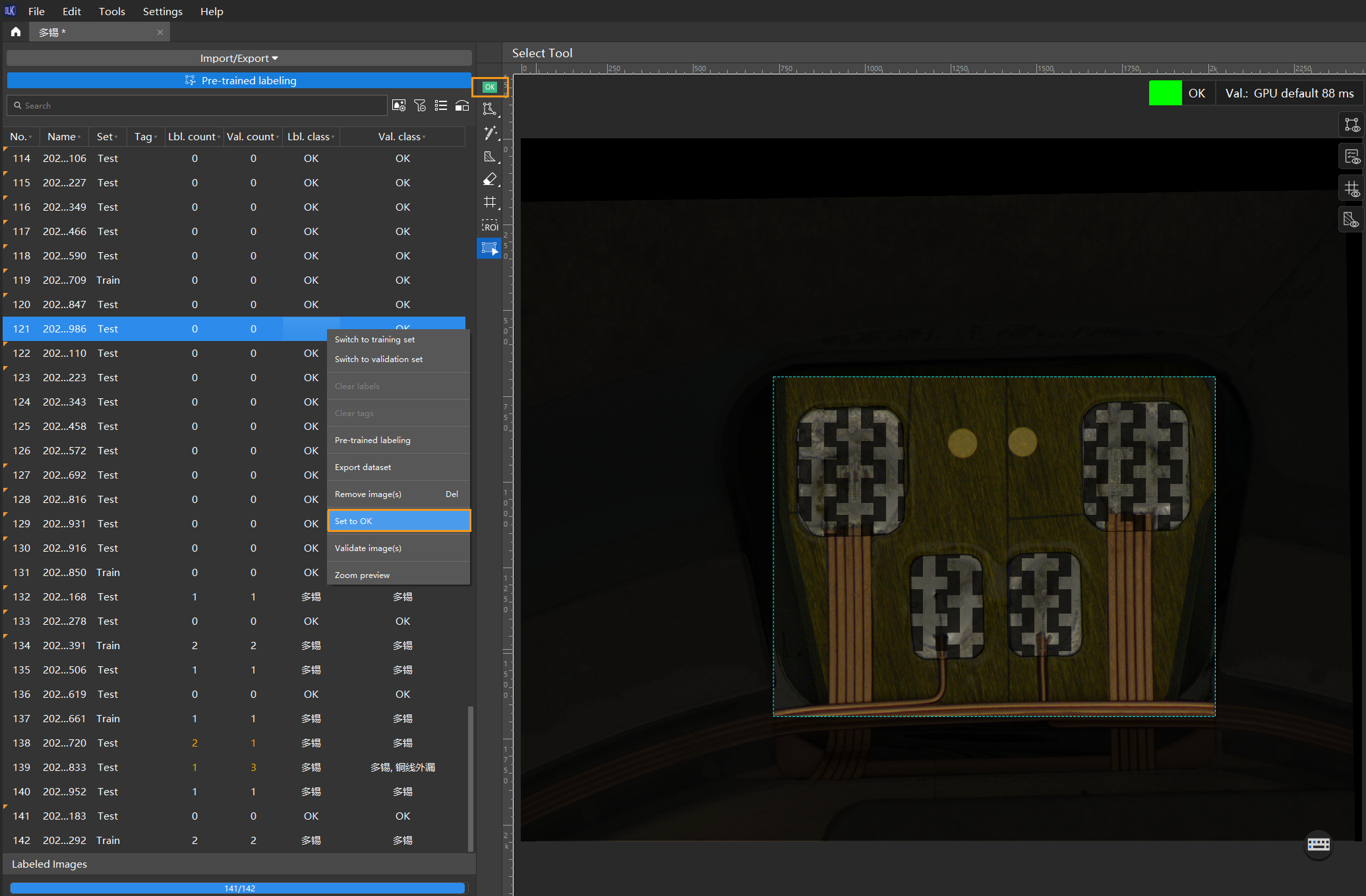
Model Training
-
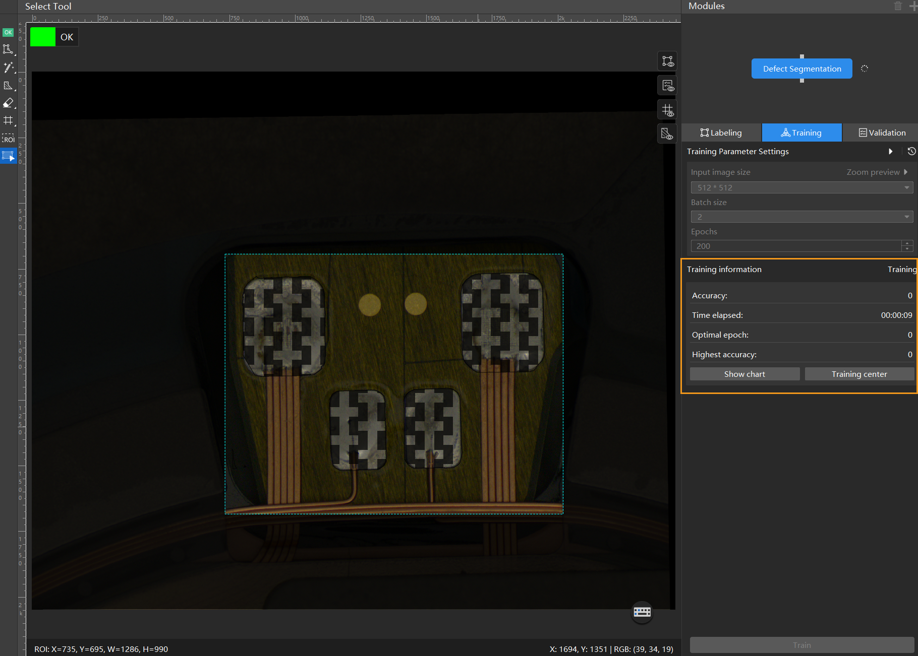
Configure parameters: Click the
 button to the right of Training Parameter Settings under the Training tab and configure the training parameters according to your needs. For explanations of each parameter, see Train a Model.
-
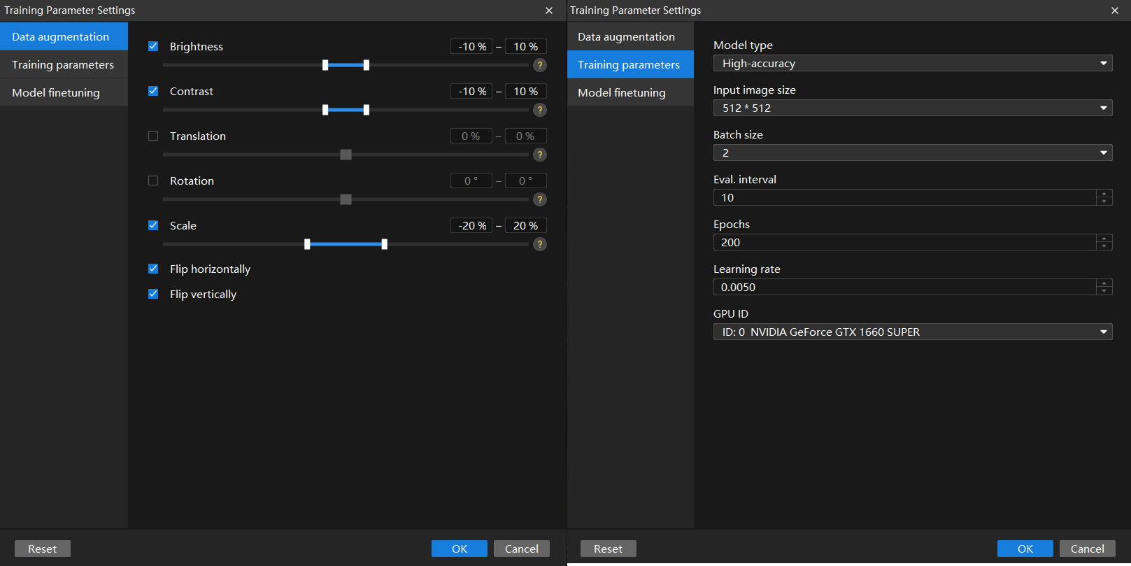
Configure data augmentation parameters to enrich the training data based on the original dataset. The purpose of data augmentation parameters is to improve the model’s generalization ability when training data is limited. In this sample project, adjust the parameter settings under the data augmentation tab according to the actual situation, as shown in the image below:
-
Even if the object placement, lighting, and other conditions are highly consistent, it is still recommended to set a certain amount of data augmentation parameters to achieve better training results. When setting data augmentation parameters, ensure that the defect characteristics in the augmented images are not distorted. Disable relevant augmentation parameters if necessary to avoid negatively impacting model training. In this sample project, excess solder defects may appear anywhere on the pads, with variations in size, brightness, and shape between defects. Lighting conditions during image capture may also vary. Therefore, no data augmentation parameters need to be disabled in this sample project.
-
Generally, it is unnecessary to set excessively large data augmentation parameter values.
-
-
Configure training parameters. In general, it is recommended to use the default settings for parameters such as Eval. interval and GPU ID.
-
If the defect segmentation task is challenging and requires high accuracy, it is recommended to set the Model type to High-accuracy. In this sample project, since the defects are relatively large with clear contours, using the High-speed model is sufficient to meet the requirements.
-
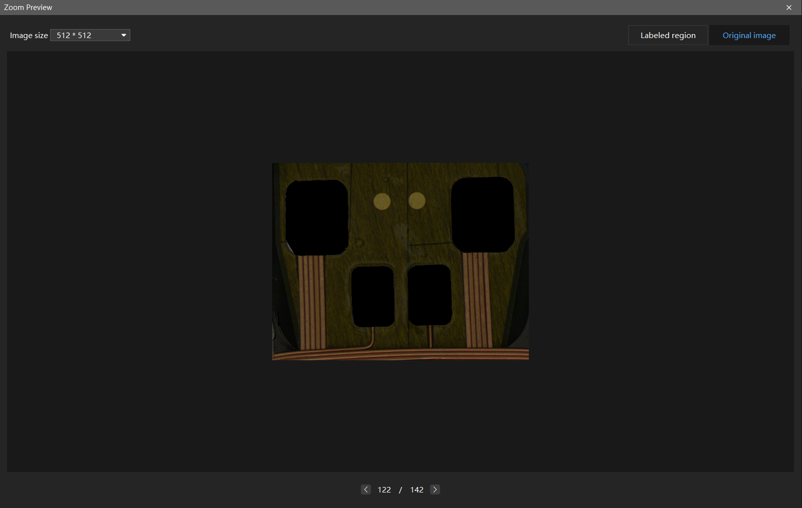
When adjusting the Input image size parameter, be sure that the original image remains clear enough to observe the defect areas in both the labeled region and original image after scaling; otherwise, the training performance may be negatively affected. You can select any image in the image list, right-click, and choose Zoom preview from the context menu to verify the image scaling effect. If the defect areas in the original image and the labeled areas in the labeled region are clearly visible, the set input image size meets the requirements.
-
When the input image size meets the requirements, using a smaller size can help speed up model training and inference.
-
Larger input image sizes help better fit the validation and defect area contours, improving model accuracy, but they will increase the number of iterations and training time.
-
If the image size is large but the defect area is small, and the labeled and defect areas are still unclear even at the maximum input image size, you can use the grid cutting tool to divide the image into equally sized smaller images, making it easier to detect small defects.
-
-
If the GPU allows, you can increase the batch size appropriately to improve training and inference speed.
-
When starting training for the first time, it is recommended to use a large total number of epochs (over 500) to better observe the accuracy curve and select the optimal model. If the total number of training epochs is too small, the model may stop training before reaching its highest accuracy. For example, in this sample project, you can set the total number of epochs to 500 before starting training for the first time.
-
-
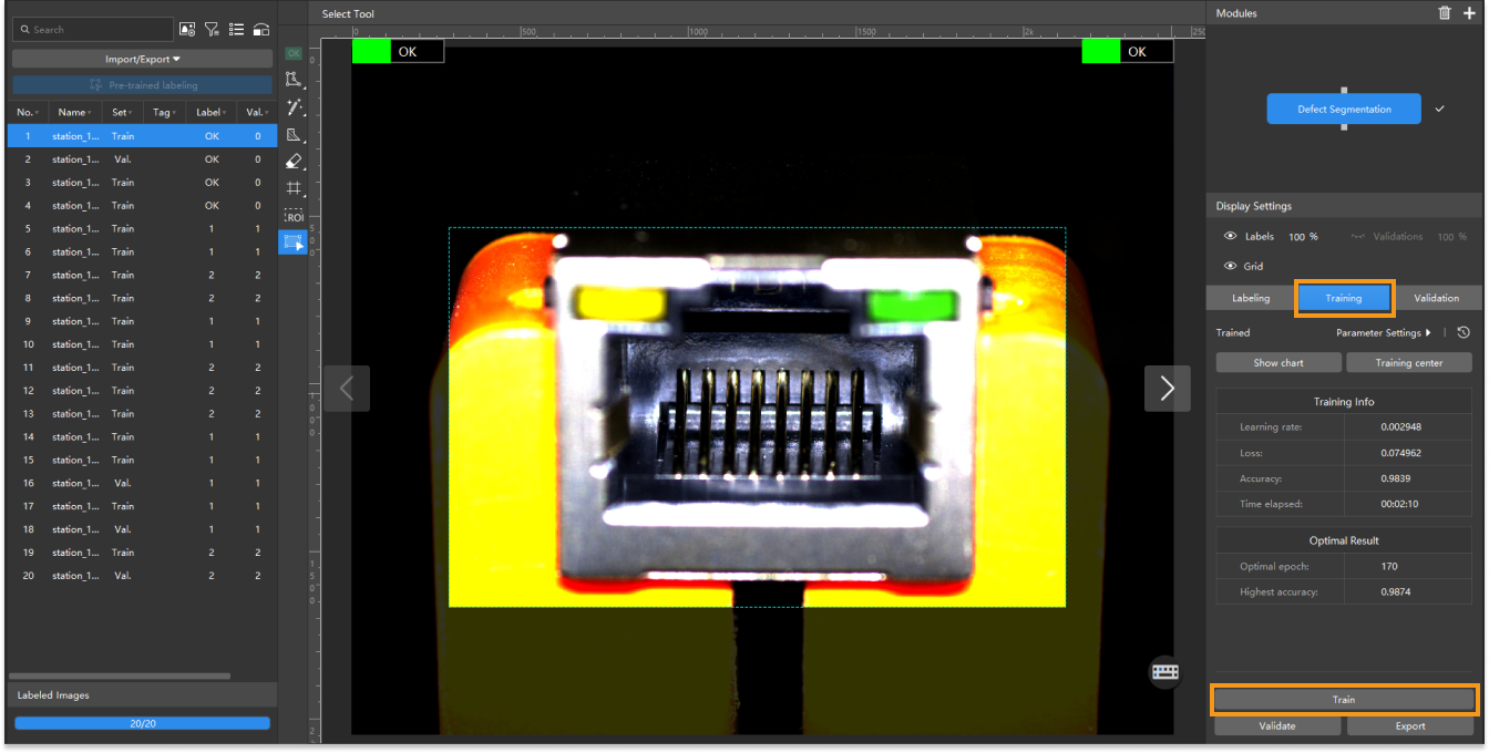
Start training: After configuring the parameters, click the Train button under the Training tab to begin training the model.
-
Monitor training progress through training information: On the Training tab, the training information panel allows you to view real-time model training details.
-
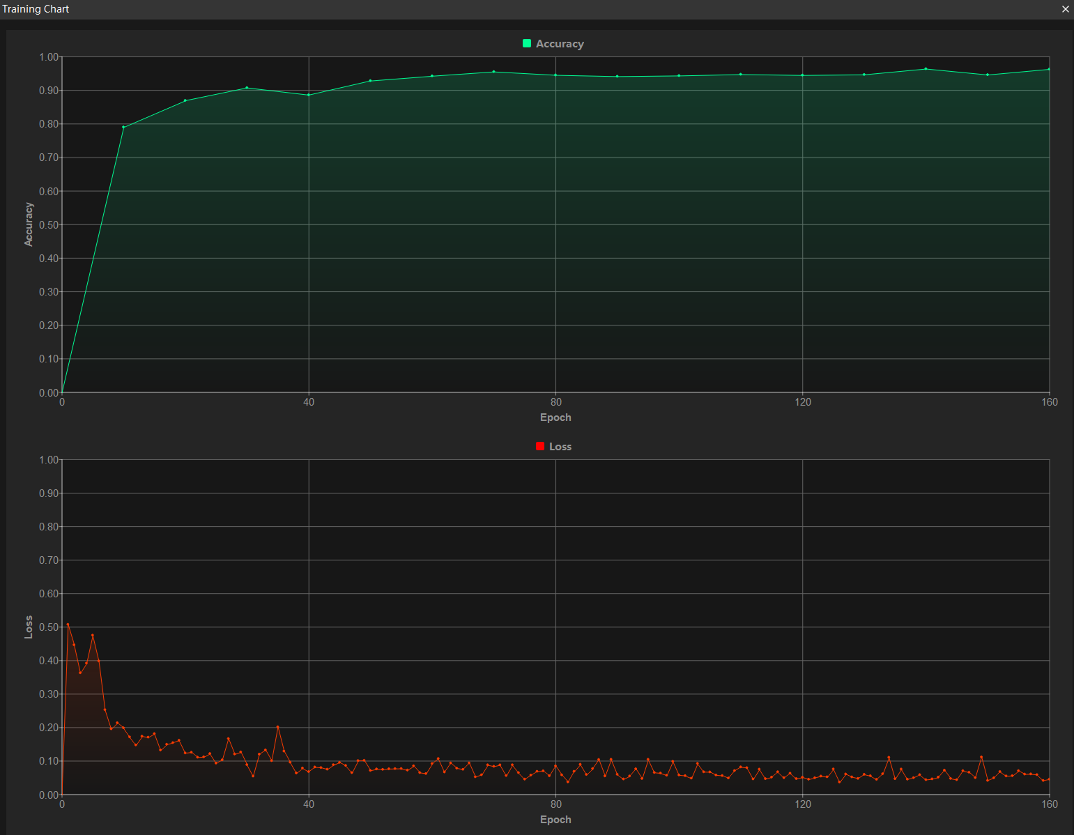
View training progress through the Training Chart window: Click the Show chart button under the Training tab to view real-time changes in the model’s accuracy and loss curves during training. An overall upward trend in the accuracy curve and a downward trend in the loss curve indicate that the current training is running properly.
-
Stop training early based on actual conditions (optional): When the model accuracy has met the requirements, you can save time by clicking the Training center button, selecting the project from the task list, and then clicking the stop icon
 to stop training. You can also wait for the model training to complete and observe parameter values such as the highest accuracy to make a preliminary assessment of the model’s performance.
| If the accuracy curve shows no upward trend after many epochs, it may indicate a problem with the current model training. Stop the model training process, check all parameter settings, examine the training set for missing or incorrect labels, correct them as needed, and then restart training. |
Model Validation
-
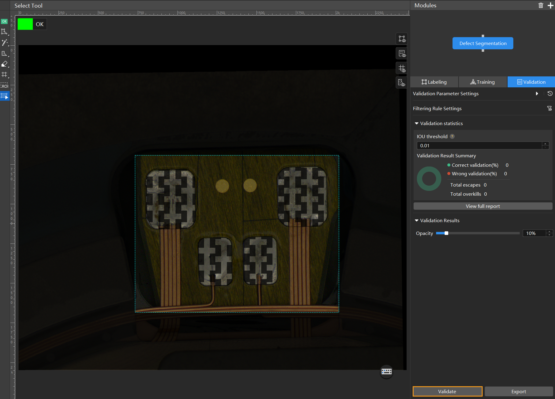
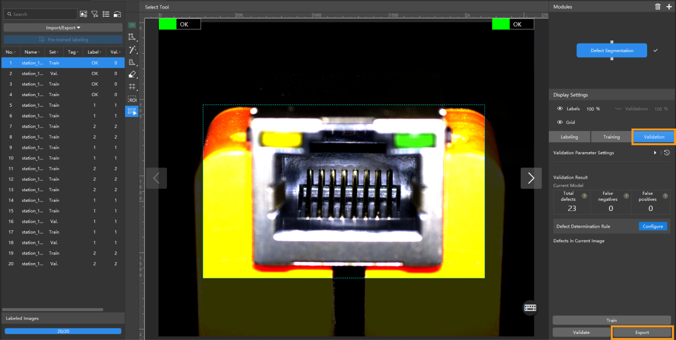
Validate the model: After training is completed or manually stopped, click the Validate button under the Validation tab to validate the model.
-
Check the model’s validation results in the training set: After validation is complete, you can view the validation result quantity statistics in the Validation statistics section under the Validation tab.
-
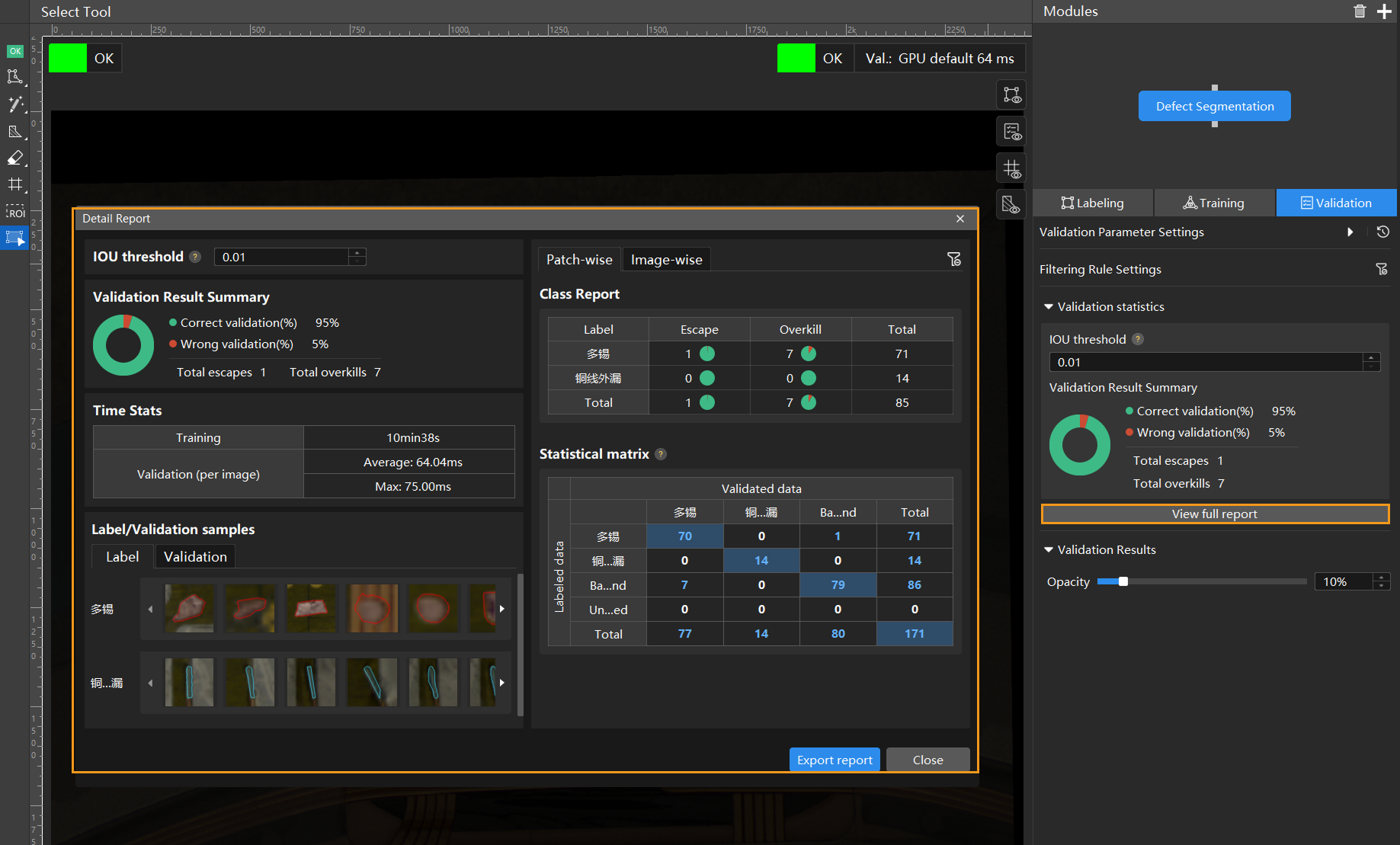
Click the View full report button to open the Detailed Report window and view detailed validation statistics.
-
The Statistical matrix in the report shows the correspondence between the validated data and labeled data of the model, allowing you to assess how well each class is matched by the model.
-
In the matrix, the vertical axis represents labeled data, and the horizontal axis represents predicted results. Blue cells indicate matches between predictions and labels, while the other cells represent mismatches, which can provide insights for model optimization.
-
Clicking a value in the matrix will automatically filter the image list in the main interface to display only the images corresponding to the selected value.
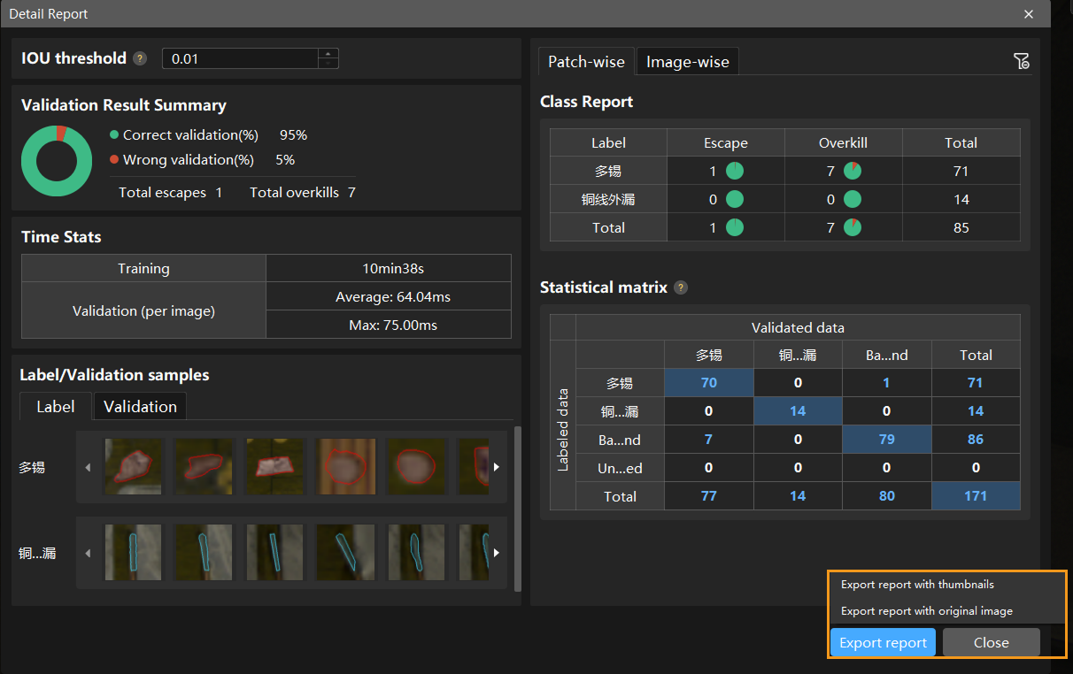
If the validation results on the training set show missed or incorrect detections, it indicates that the model training performance is unsatisfactory. Please check the labels, adjust the training parameter settings, and restart the training. You can also click the Export report button at the bottom-right corner of the Detailed Report window to choose between exporting a thumbnail report or a full-image report.
You don’t need to label and move all images with missed or incorrect detections in the test set into the training set. You can label a portion of the images, add them to the training set, then retrain and validate the model. Use the remaining images as a reference to observe the validation results and evaluate the effectiveness of the model iteration. -
-
Restart training: After adding newly labeled images to the training set, click the Train button to restart training.
-
Recheck model validation results: After training is complete, click the Validate button again to validate the model and review the validation results on each dataset.
-
Fine-tune the model (optional): You can enable developer mode and turn on Finetune in the Training Parameter Settings dialog box. For more information, see Iterate a Model.
-
Continuously optimize the model: Repeat the above steps to continuously improve model performance until it meets the requirements.
Model Export
Click Export. In the pop-up dialog box, select a directory to save the exported model, and click Export.
The exported model can be used in Mech-Vision, Mech-DLK SDK and Mech-MSR. Click here to view the details.