Use the Defect Segmentation Module
Please click here to download an image dataset of network ports, an example provided by Mech-DLK. Different from the content in Train Your First Model, in this section, we will use a Defect Segmentation module and train a model to detect the defects such as deformations and fractures on the network ports.
| You can also use your own data. The usage process is overall the same, and the labeling part is different. |
-
Create a new project and add the Defect Segmentation module: Click New Project in the interface, name the project, and select a directory to save the project. Click
 in the upper right corner of the Modules panel and add the Defect Segmentation module.
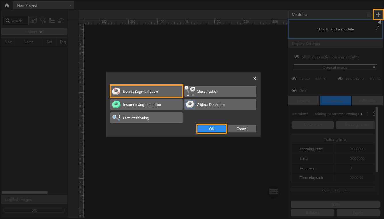
-
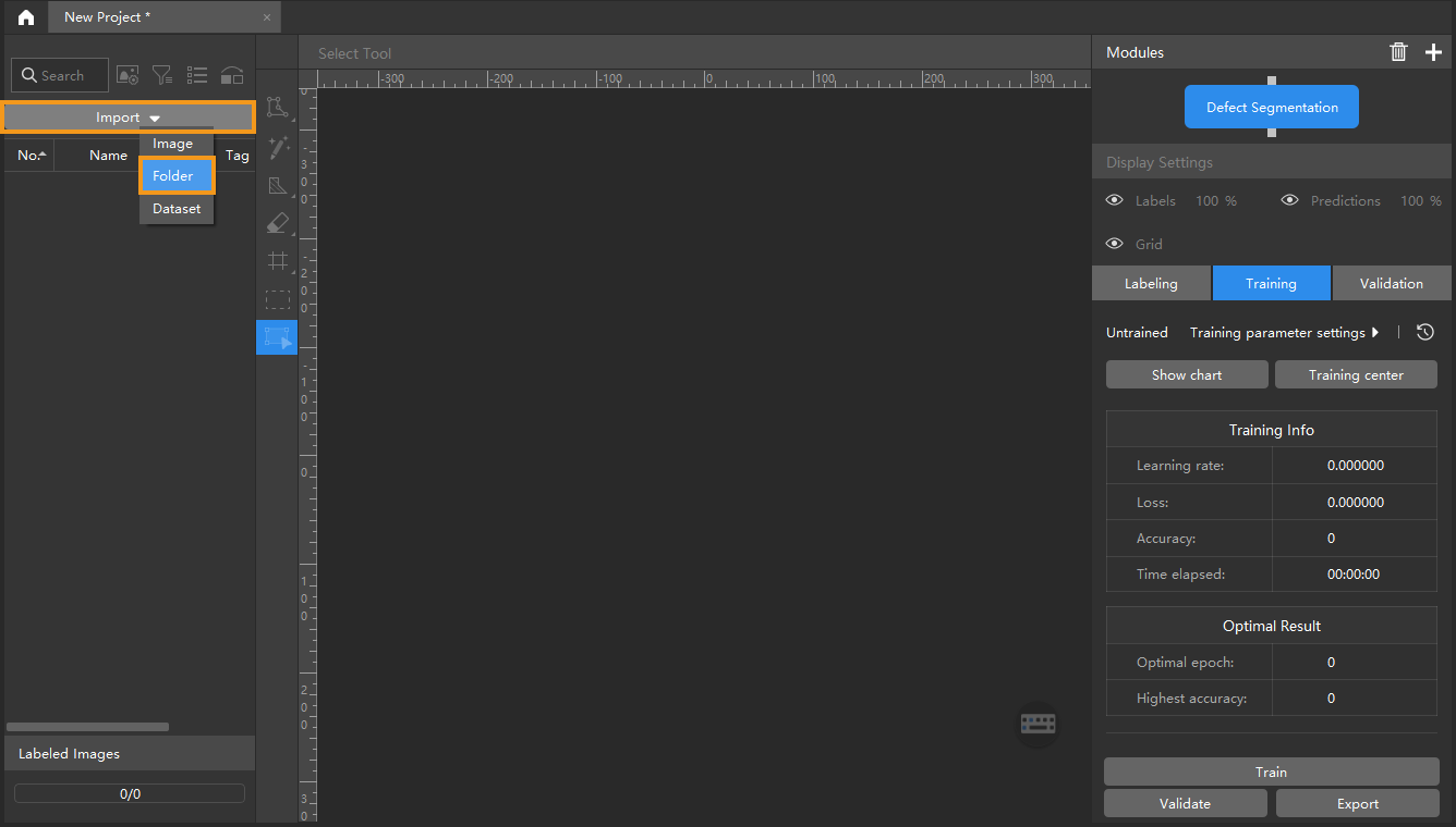
Import the image dataset of network ports: Unzip the downloaded dataset file. Click the Import button in the upper left corner, select Folder, and import the image dataset. The pins in the images can be deformed, fractured, or intact.
-
Select an ROI: Click the ROI Tool button
 and adjust the frame to select the pins in the image as an ROI, and click Apply to save the settings. Setting the ROI can avoid interferences from the background and reduce processing time. Setting the ROI can avoid interferences from the background and reduce processing time.
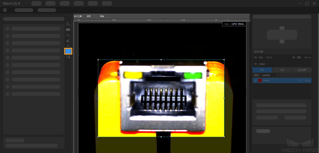
-
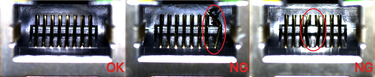
Labeling: In this example, you will need to label the OK images and NG images in each dataset. OK means that the connectors meet quality requirements and NG means that there are defects such as deformations and fractures on the Ethernet ports.
-
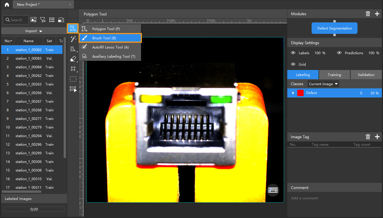
For NG images, right-click the Polygon Tool and select a suitable tool to select the defect regions. In this example, it is recommended to use the Brush Tool. During labeling, the brush should be close to the edge of the defect to avoid the inclusion of a large number of non-defective areas. Click here to view how to use labeling tools.
-
For OK images that do not contain any defect, select the image and then right-click and select Set to OK in the context menu.

-
-
Split the dataset into the training set and validation set: Please make sure that both the training set and validation set include images with all types of defects and at least one OK image. This can guarantee that the algorithm can learn all different types of defects and validate the images with different defects properly. If the default training set and validation set cannot meet this requirement, please right-click the individual image and switch it to the training/validation set manually.
-
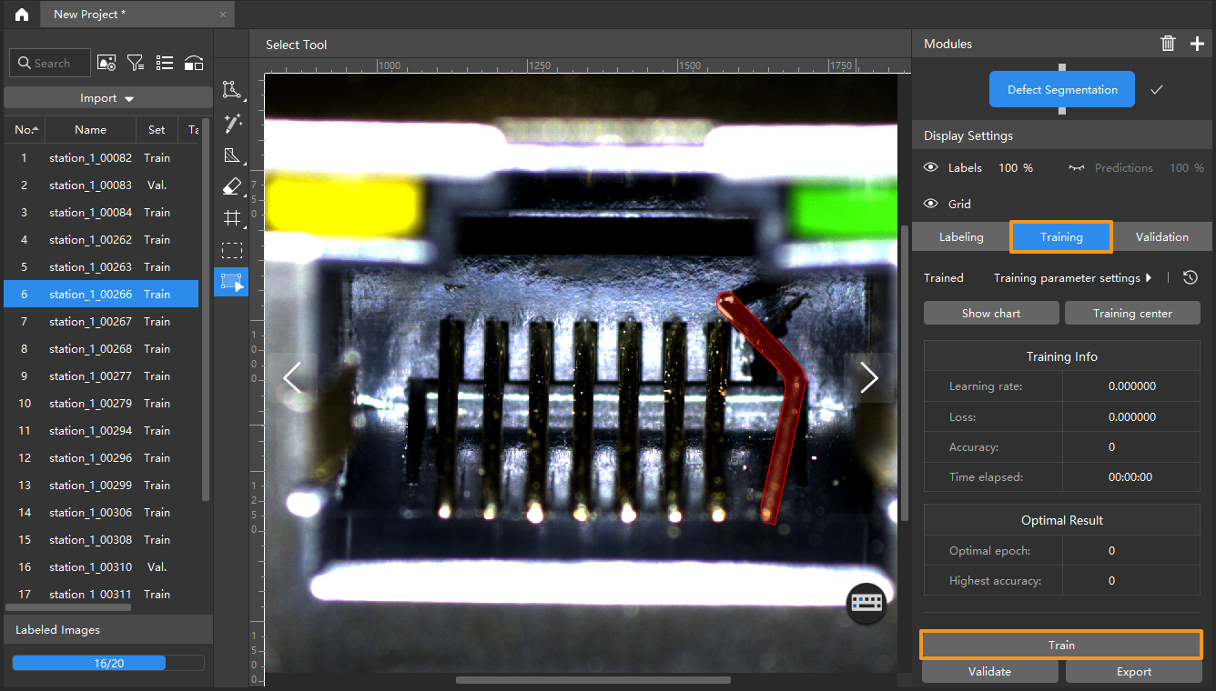
Train the model: Keep the default training parameter settings and click Train to start training the model. Click here to view the instructions on training parameter configuration.
-
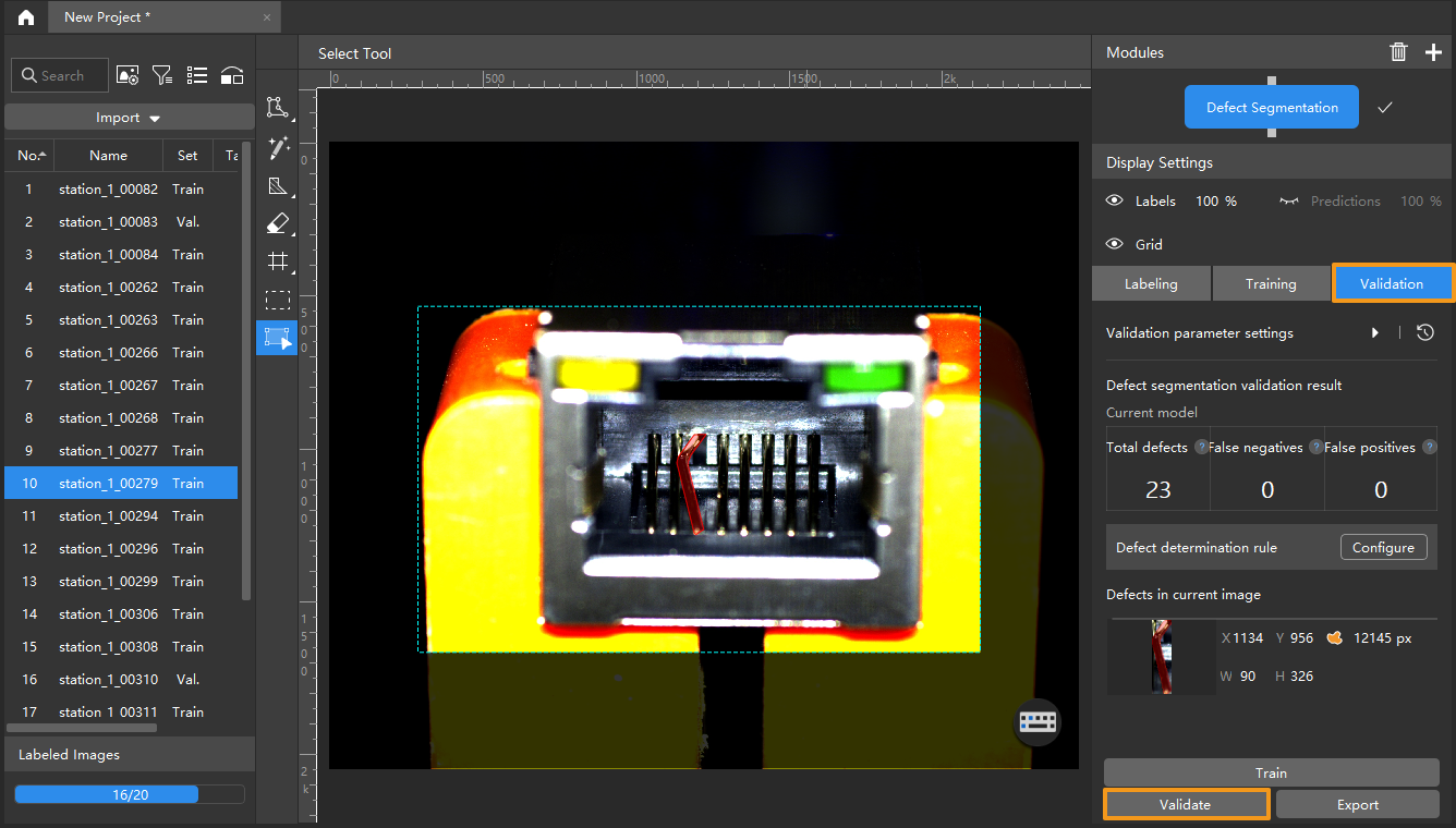
Validate the Model: After the training is completed, click Validate to validate the model and check the results. Click here to view the instructions on validation parameter configuration. You can also modify the Defect determination rule to filter results.
-
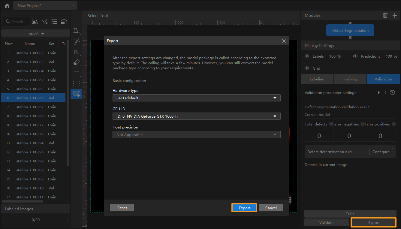
Export the model: Click Export, set parameters of the model to be exported in the pop-up window, and then click Export and select a directory to save the exported model.
The exported model can be used in Mech-Vision and Mech-DLK SDK. Click here to view the details.