Use the Defect Segmentation Module
Please click here to download an image dataset of network ports, an example provided by Mech-DLK. In this topic, we will use a Defect Segmentation module and train a model to detect defects such as deformations and fractures on the network ports.
| You can also use your own data. The usage process is overall the same, but the labeling part is different. |
Workflow
-
Create a new project and add the Defect Segmentation module: Click New Project in the interface, name the project, and select a directory to save the project. Click
 in the upper right corner of the Modules panel and add the Defect Segmentation module.
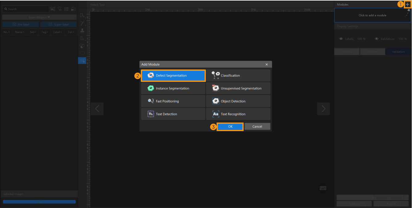
-
Import the image data of network ports: Unzip the downloaded file. Click the Import/Export button in the upper left corner, select Import Folder, and import the image folder. The pins in the images can be deformed, fractured, or intact.
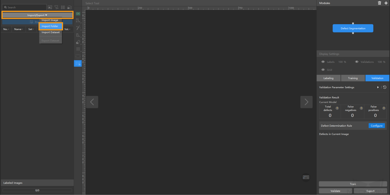
When you select Import Dataset, you can only import datasets in the DLKDB format (.dlkdb), which are datasets exported from Mech-DLK. -
Select an ROI: Click the ROI Tool button
 and adjust the frame to select the pins in the image as an ROI. Then, click the
  button in the lower right corner of the ROI to save the setting. Setting the ROI can avoid interferences from the background and reduce processing time, and the ROI boundary should be as close to the outer contours of the object as possible.
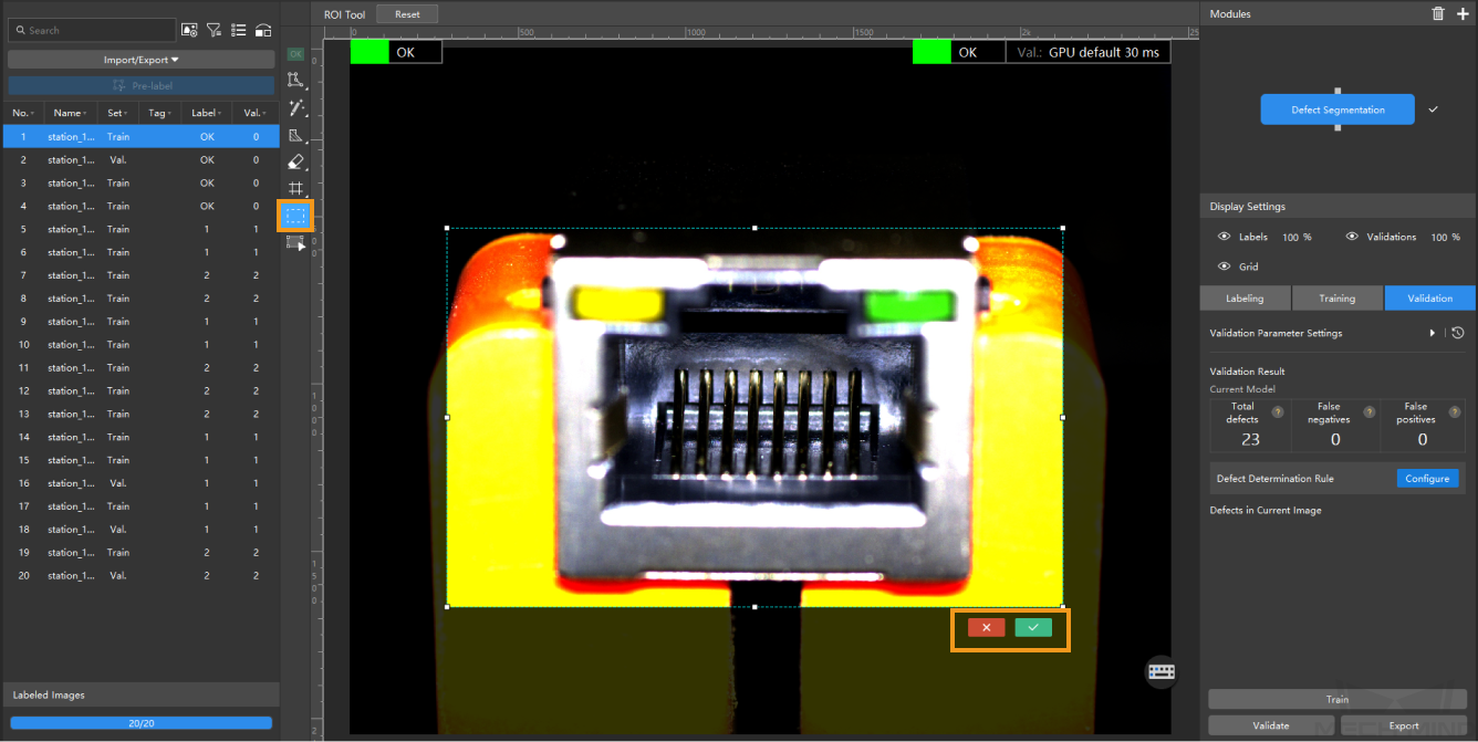
The same ROI setting will be applied to all images, so it is necessary to ensure that objects in all images are within the ROI, especially in scenarios where the object positions/sizes are not fixed. -
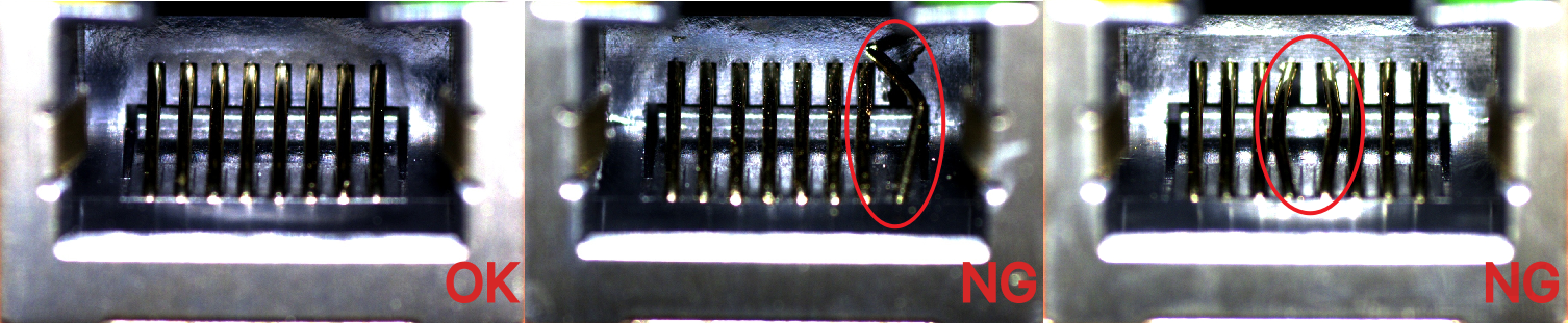
Labeling: In this example, you will need to label the OK images and NG images in each dataset. OK means that the connectors meet quality requirements and NG means that there are defects such as deformations and fractures on the Ethernet ports.
-
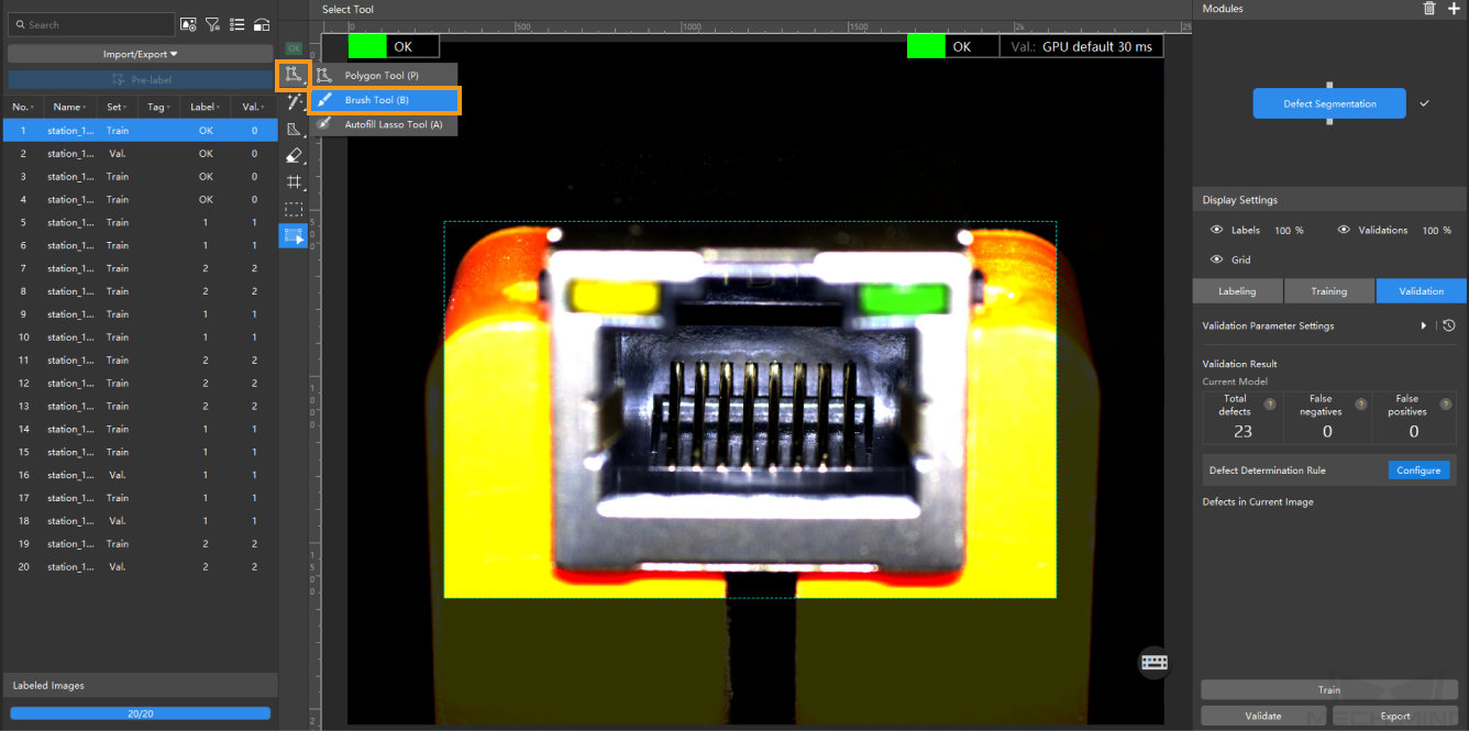
For NG images, right-click the Polygon Tool and select a suitable tool to select the defect regions. In this example, it is recommended to use the Brush Tool. During labeling, the brush should be close to the edge of the defect to avoid the inclusion of a large number of non-defective areas. Click here to view how to use labeling tools.
-
For ambiguous defects, when it is impossible to judge whether the defect judgment criteria are met, the Mask Polygon Tool can be used to cover the defect regions.
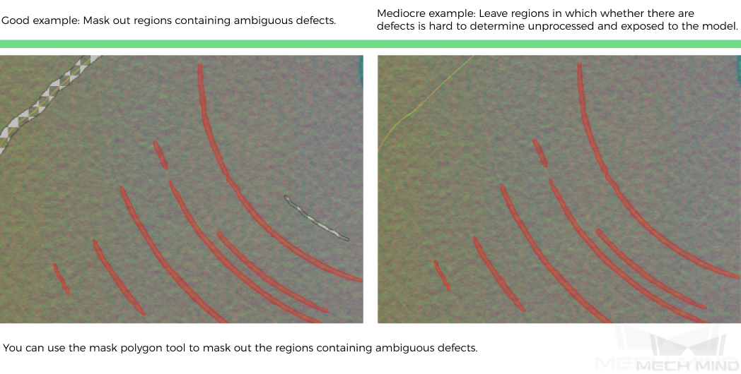
When there are multiple defects in the image, if it is impossible to judge whether each defect meets the defect judgment criteria, you can delete the current image to avoid affecting the model training effect. -
For OK images, select an image and click the OK Label
 on the labeling toolbar. The image will be labeled as OK.
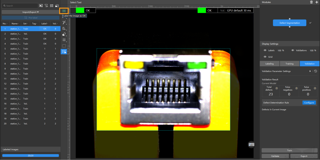
-
-
Split the dataset into the training set and validation set: Please make sure that both the training set and validation set include at least one OK image and images with all types of defects, in terms of shape, background, color, size, etc. When the features in OK images do not differ across images, the number of OK images can be relatively small. This can guarantee that the algorithm can learn all different types of defects and validate the images with different defects properly. If the default training set and validation set cannot meet this requirement, please right-click the individual image and switch it to the training/validation set manually.
-
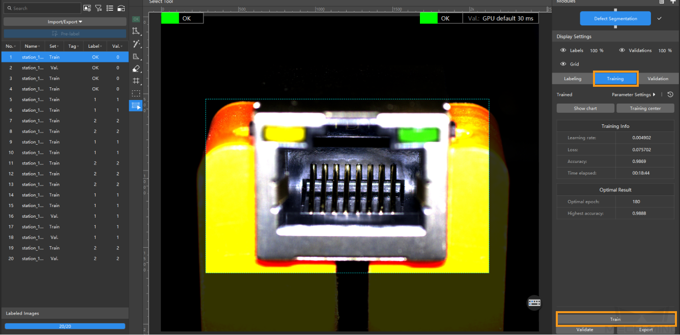
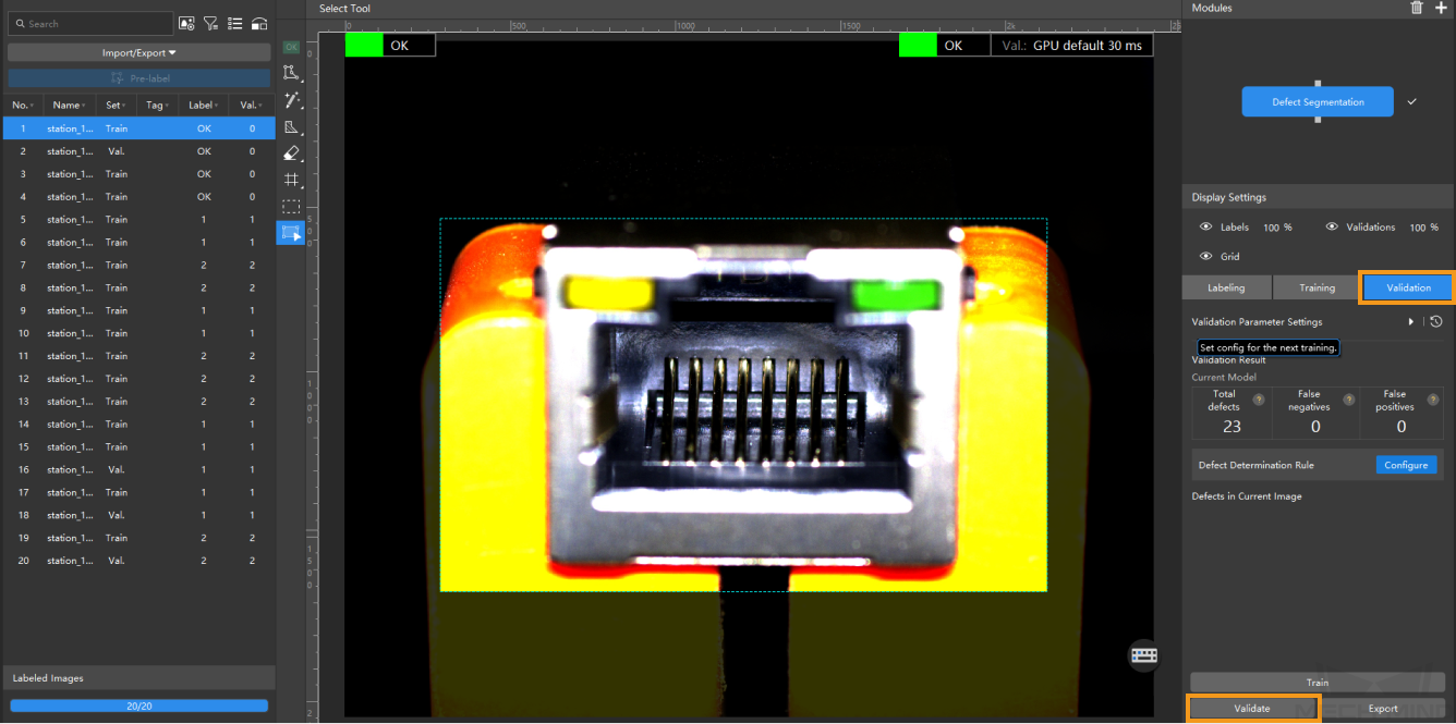
Train the model: Keep the default training parameter settings and click on Train to start training the model.
-
Validate the Model: After the training is completed, click Validate to validate the model and check the results. You can also modify the Defect determination rule to filter results.
After you validate a model, you can import new image data to the current module and use the pre-labeling feature to perform auto-labeling based on this model. For more information, see Pre-labeling.
-
Export the model: Click Export and select a directory to save the trained model.
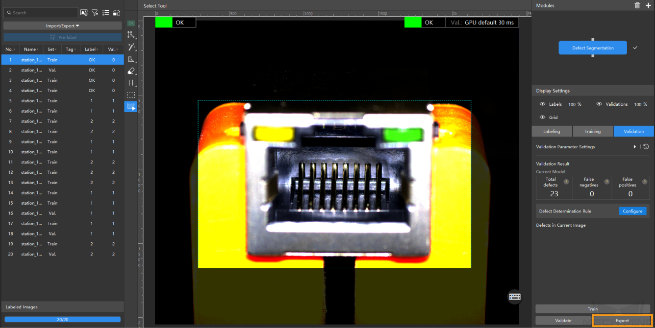
The exported model can be used in Mech-Vision and Mech-DLK SDK. Click here to view the details.