Basic Concepts
This section introduces the key terms and basic concepts in Mech-Metrics and helps users understand the relationships between the system architecture and the main objects. For more terms and concepts, refer to Terms and Concepts.
- Mech-Metrics Project
-
A Mech-Metrics project is a project created by the user in Mech-Metrics to maintain and manage an inline measurement project. A Mech-Metrics project contains a complete set of measurement configurations, which enables the management of the entire measurement process from part import, reference frame establishment, and feature configuration to data collection and analysis.
- Mech-MSR Solution and Project
-
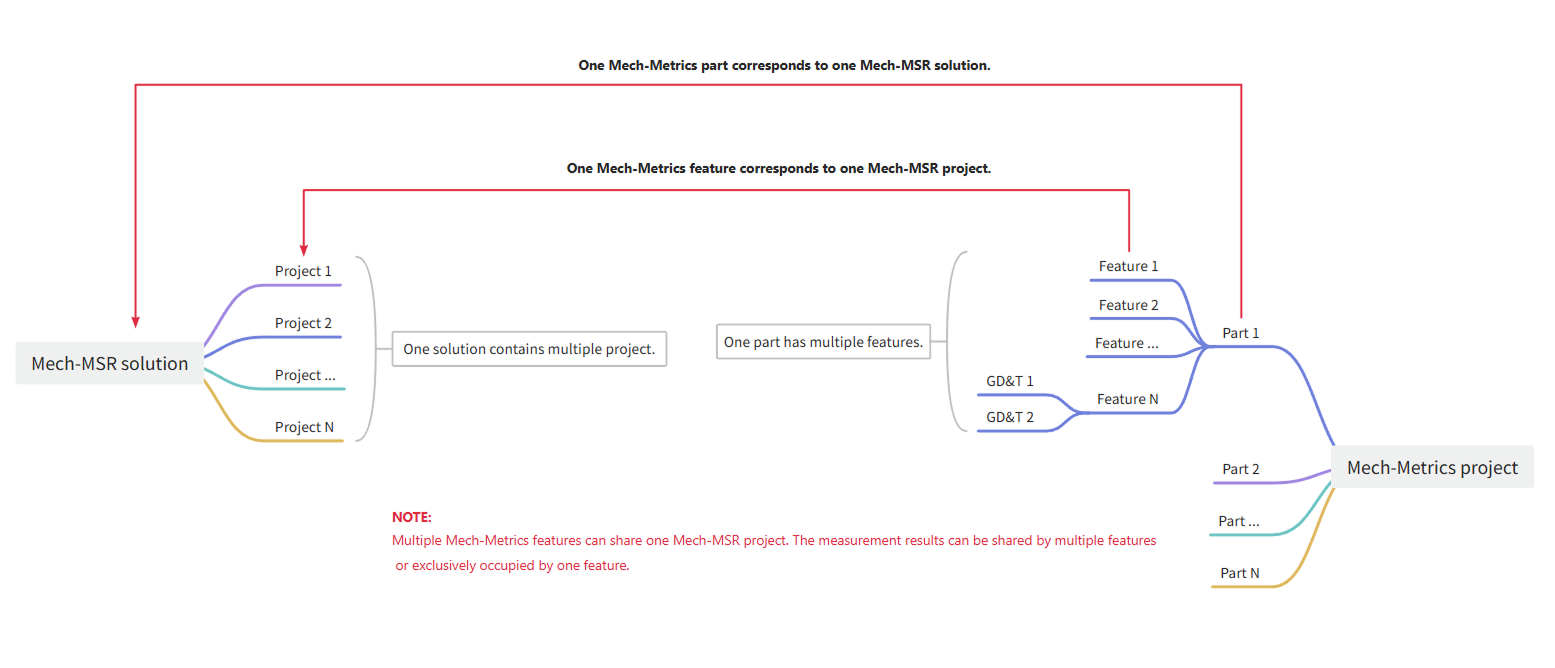
A Mech-MSR solution refers to a Mech-MSR solution specifically configured for measuring a specific part. When you use Mech-Metrics, you need to associate a part with its Mech-MSRsolution.
A Mech-MSR project is a specialized Mech-MSR project dedicated to measuring a specific feature of a part. When you use Mech-Metrics, you need to associate the feature with its Mech-MSRproject.
The correspondence between Mech-Metrics resources and Mech-MSR resources is summarized as follows:
- Part
-
A part refers to an individual workpiece that is processed or assembled during production.
- Feature
-
A feature refers to specific geometric elements or attributes of a part, such as its shape, dimensions, and so on. The features that can be measured in this software include circle, slot, cylinder, point, line, plane, rectangle, pattern, distance, and angle.
- Control Item
-
Control items refer to the measurement children of a feature. Control items are used to constrain the feature. For example, the control items of a circle feature include dimension control items (X, Y, Z, and radius), GD&T control items (profile of a surface, parallelism, perpendicularity, position, and concentricity), and custom control items.
- Measurement Group
-
A measurement group is a collection of features, used to control the range of features involved in measurement and judgment in a single measurement task. Measurement groups are divided into fixed groups and rotating groups. You can create and manage measurement groups in the Measurement Group Editor, and the robot program specifies the measurement groups participating in the measurement through the measurement group ID in command 801.
- Fixed group
-
The features in a fixed group participate in every measurement. The ID of the fixed group is always 10.
- Rotating group
-
Each rotating group contains multiple alternative features. Only one rotating group participates in each measurement, achieving a “round-robin use” effect. Rotating groups are used together with the fixed group, and the composite ID ranges from 11 to 9999.
- Full inspection and partial inspection
-
Full inspection and partial inspection are modes for controlling the measurement range in earlier versions. For compatibility with earlier versions, the measurement group ID values 0–2 in command 801 retain this behavior: 0 uses the current configuration; 1 indicates full inspection (all features are included); 2 indicates partial inspection (only the fixed group is included).
- Nominal Value
-
Nominal values refer to the ideal or target dimensions of a feature, which are the standard values that the designer expects the part to achieve during the manufacturing process. The nominal values serve as a reference to determine the shape, size, and other design requirements of the part.
- Measured Value
-
Measured values refer to the actual measurement results of features provided by Mech-MSR and processed by Mech-Metrics. After importing the measured values into Mech-Metrics, the coordinates are transformed according to the newly created reference frame, and all measurement results are expressed and analyzed according to this reference frame.
- Tolerance
-
Tolerance refers to the difference between the maximum and minimum allowable dimensions based on a nominal value. For example, if a cylinder is designed to have a length of 50 mm and a tolerance of ±0.1 mm, it is eligible within the range of 49.9 mm to 50.1 mm.
- Alignment
-
Alignment refers to establishing the spatial relationship between different reference frames (such as the robot reference frame and the vehicle body reference frame), so as to accurately transform the measured values in the robot reference frame into those in the vehicle body reference frame or other target reference frames. Alignment is the foundation for unifying the data in multiple reference frames and aligning measurement results.
- Part Alignment
-
Part alignment refers to defining a reference frame based on datum features of the part (such as holes, edges, and datum surfaces). Since the reference feature of each part may be different, when a part is used for alignment, the reference frame of each part may also be different. This method can appropriately relax the requirements on the accuracy of fixtures, suitable for scenarios where the reference features of the part are easy to recognize and the fixturing methods vary. The transformation path is as follows: robot reference frame → vehicle body reference frame.
- Fixture Alignment
-
Fixture alignment refers to establishing a reference frame for the fixture (the equipment used to hold the part in place) based on measured features of the fixture. Due to the fixed nature of the fixture, all parts to be measured can be converted to the fixture reference frame by performing alignment once. This method has a high requirement on the accuracy of the fixture, which is suitable for mass production and fixture reuse scenarios. The transformation path is as follows: robot reference frame → vehicle body reference frame.
- Scope features
-
Scope features refer to the features that an alignment method applies to. Each alignment method can specify its scope features, and the same feature cannot be occupied by two activated alignment methods at the same time.
- Basis features
-
Basis features refer to the features used to construct an alignment method. Basis features are always included in the scope features of the alignment method and cannot be changed.
- Correlation
-
Correlation refers to the degree of consistency between the measurement results of two different measurement devices when measuring the same dimension of the same part.
- Correlation Analysis and Compensation
-
Correlation analysis and compensation refer to analyzing the relationship between the measurement results of two different measuring devices, followed by compensating the results of one device to improve the reliability of the device.
- Measurement Record
-
Measurement records refer to the measurement records stored in the historical data of the software.
- Measurement Report
-
Measurement report is the official document that summarizes, analyzes, and displays the measurement results of parts. Reports usually contain information about measurement objects, features and control items, measurement data, deviation analysis, tolerance judgment, and statistical analysis. Mech-Metrics supports custom PDF-format and table-format measurement reports to meet different archiving, sharing, and data processing requirements. Measurement reports are widely used in quality traceability, process control, and delivery scenarios.