Workflow
This section describes the complete workflow of the Repair Viewer from deployment to production use.
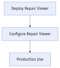
The workflow of the Repair Viewer consists of the following three stages:
-
Deploy the Repair Viewer: Install and enable the Repair Viewer. The operations in this stage are performed only once during deployment.
-
Configure the Repair Viewer: Create a configuration for the repair station, add views and feature annotations, and start the PLC communication service.
-
Production use: The Repair Viewer displays the part measurement results and helps repair operators complete repair operations.
Deploy the Repair Viewer
The operations in this stage need to be performed only once during deployment.
Install the Repair Viewer
The Repair Viewer is installed together with the Mech-Metrics software.
-
On the secondary IPC, install the Mech-Metrics software suite by referring to Installation Guide.
-
After the installation is complete, double-click
repair_viewer.exein theMech-Metrics\binfolder of the installation directory to start the Repair Viewer.
Enable the Repair Viewer
Before using the Repair Viewer, complete the following operations on the primary IPC:
-
On the primary IPC, start the Mech-Metrics software, click in the menu bar, and enable the Repair Viewer plugin (plugin name:
repair_viewer_service) in the plugin manager. -
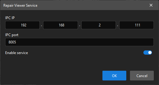
In the menu bar, click , and the Repair Viewer Service dialog box will pop up.
-
In the Repair Viewer Service dialog box, set the following parameters:
-
IPC IP: Enter the IP address of the IPC that runs the Mech-Metrics software (that is, the primary IPC).
-
IPC port: Enter the port number monitored by the Repair Viewer service.
-
Enable service: Turn on the switch.
-
-
Click OK to enable the Repair Viewer service.
After the service is started successfully, the Mech-Metrics logs will display “Repair Viewer service started” and the related listening address information.
|
Configure the Repair Viewer
After the deployment is complete, create a configuration and complete the related settings for the repair station on the secondary IPC.
Create a Configuration
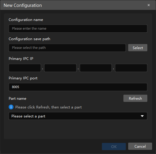
Start the Repair Viewer on the secondary IPC, and then click New Configuration on the start page. The New Configuration dialog box will pop up.
In the New Configuration dialog box, set the following information:
-
Configuration name: Enter the name of the current configuration. The configuration name cannot be empty and cannot duplicate an existing configuration name.
-
Configuration save path: Click Select to select the save path of the configuration.
-
Primary IPC IP and Primary IPC port: Enter the IP address and port of the primary IPC. The plugin will automatically connect to the primary IPC. If the connection fails, check that the IP address and port are correct.
-
Part name: Click Refresh, and the plugin will retrieve the list of configured parts from the primary IPC. Then select the part corresponding to the current repair station from the list.
If no part list is retrieved, check that the primary IPC is connected and that parts have been configured in Mech-Metrics.
After the settings are complete, click OK to save the configuration and enter the main interface.
Add Views and Feature Annotations
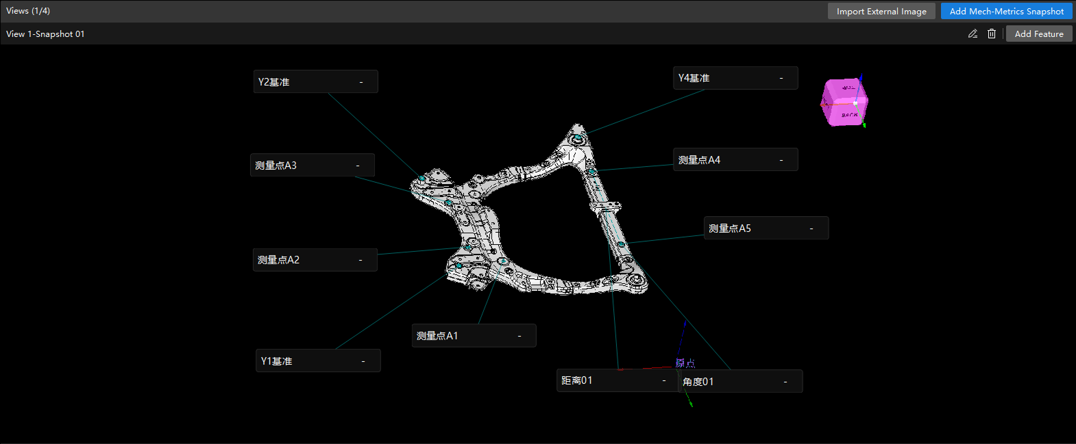
After entering the main interface, add views and feature annotations for the part as a reference for repair operations.
|
It is recommended to add Mech-Metrics snapshots as views. After a snapshot is added as a view, the features in the snapshot will be automatically added. |
-
Add views:
-
Add a Mech-Metrics snapshot to the 3D view or import an external image.
-
To adjust a view, you can edit the view name, replace the view image, or delete the view.
-
-
Add feature annotations:
-
Click Add Feature in the view, and the plugin will retrieve the feature list of the current part from the primary IPC.
-
Select a position and click to add the feature to the view, and the plugin will generate the corresponding annotation card.
-
To adjust an annotation card, you can edit its display name or delete unneeded annotation cards.
-
Start the PLC Communication Service
The Repair Viewer interacts with the PLC device through the PLC communication service.
-
In the menu bar, click .
-
In the PLC Communication Service Settings dialog box, set Local IP and Local port, and turn on Enable service.
-
Click OK to start the PLC communication service.
After the service is started, the PLC Communication Service Status in the status bar will be updated, and the logs will display the listening port information.
|
The PLC device communicates with the Repair Viewer using the TCP ASCII protocol. The PLC device can send command 805 (query part historical data) to retrieve part measurement data. |
Production Use
After the preceding configuration is complete, the Repair Viewer is ready for production use.
During production, the Repair Viewer typically works as follows:
-
The PLC device triggers a query (command 805), and the Repair Viewer retrieves the measurement data of the specified part from the primary IPC.
-
The main interface displays the judgment result, measurement results, and feature annotations in the views of the part.
-
The repair operator clicks NG to filter non-conforming features, locates the areas that require repair based on the annotation cards in the views, and completes the repair operations.
-
The status bar displays the Part Name, Part SN, Task Started At, and the status of each connection of the current part in real time, helping you monitor the running status of the plugin.