Alignment Operation Guide
The measured values obtained by Mech-Metrics from Mech-MSR are in the robot reference frame, while the nominal values picked from the 3D model are in the vehicle reference frame. To compare measured values with nominal values, you need to convert the measured values to the vehicle reference frame. This process is called alignment.
This section introduces the concepts related to alignment and how to use the two alignment functions.
Reference Frames
Alignment involves the following three reference frames:
|
When deploying an inline measurement application, you also need to understand how the following reference frames relate to the robot reference frame, so that you can understand how measured values are generated:
-
Camera reference frame {C}: fixed to the camera. Its origin is typically at the camera optical center, and the Z-axis follows the camera optical axis.
-
Surface-data reference frame {S}: determined by camera imaging and projection parameters, and used to represent part surface point clouds and measured features.
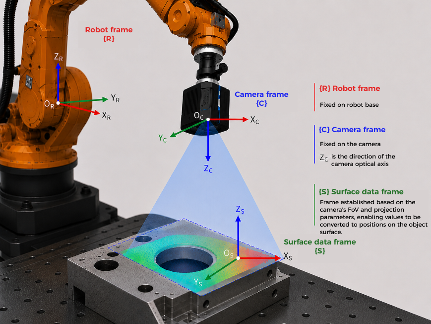
The relationship among these three reference frames in the inline measurement system can be summarized as follows:
-
First, obtain measured points and feature results in the surface-data reference frame {S}.
-
Then, convert the data to the camera reference frame {C} through camera parameters.
-
Finally, convert the data to the robot reference frame {R} based on robot hand-eye calibration results (extrinsic parameters).
You can understand the coordinate conversion chain as: {S} → {C} → {R}.
In essence, alignment is performed after measured values are already in the robot reference frame, and further establishes the relationship between the robot reference frame and the vehicle reference frame, so that measured values can be converted into the vehicle reference frame and compared with nominal values.
Alignment Methods
Mech-Metrics supports two alignment methods: part alignment and fixture alignment. The choice of alignment method should be consistent with the method used by CMM-based measurements.
|
| The placement of the part in the inline measurement system should be consistent with its placement on the CMM, adopting either a horizontal or vertical orientation. |
Alignment Features
If you need to perform part alignment, use the RPS alignment function; if you need to perform fixture alignment, use the best-fit alignment function.
|
For detailed instructions, please refer to: