Create and Modify a Feature
After you import the part model and associate a Mech-MSR solution for the part, you need to create a feature for the part. This section describes how to create, modify, and delete a feature.
Create a Feature
The software can create the following ten features: circle, slot, cylinder, point, line, plane, rectangle, pattern, distance, and angle. Determine the type and number of features to be created according to the actual measurement requirements.
Create a Circle Feature
Please follow the steps below to create a circle feature:
-
On the Mech-Metrics Configuration interface, under the Feature tab, click Circle.
-
In the Create Circle Feature dialog box, set the following information:
-
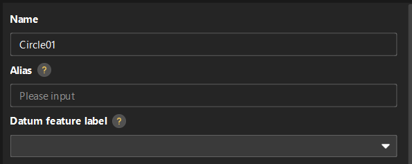
Set Name, Alias, and Datum feature label based on actual situation.
-
Alias: Used to associate the feature name in the CMM report.
-
Datum feature label: When this feature is used as the datum feature, it needs to be labeled. Datum feature labels are used in GD&T controls. For more information, see Configure GD&T Control Items.
-
-
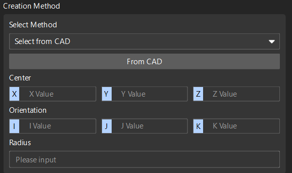
Set the creation method: The Select method is Select from CAD by default. The software will automatically input Center (X, Y, Z), Orientation (I, J, K) and Radius.
-
Set the measurement method: The Select method is Mech-MSR project by default. Select the project corresponding to the feature in the drop-down list of the Name, and set the Parameter recipe and Result mode according to needs.
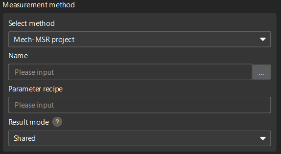
Result mode: Set the method to use the measurement result of the feature binding project.
-
Shared: When a feature-bound project finishes running, all features bound to the project will parse the measurement results.
-
Exclusive: When the project bound by a feature finishes running, only the feature that triggered the project to run will parse the measurement result.
-
-
-
Click OK.
Create a Slot Feature
Follow the steps below to create a slot feature:
-
In the Configuration interface of Mech-Metrics, under the Feature tab, click Slot.
-
In the Create Slot Feature dialog box, set the following information:
-
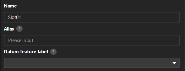
Set Name, Alias, and Datum feature label based on actual situation.
-
Alias: Used to associate the feature name in the CMM report.
-
Datum feature label: When this feature is used as the datum feature, it needs to be labeled. Datum feature labels are used in GD&T controls. For more information, see Configure GD&T Control Items.
-
-
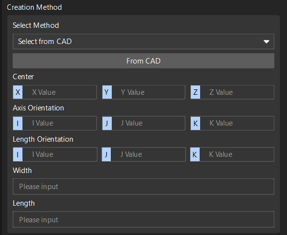
Set the creation method: The Select method is Select from CAD by default. The software will automatically input Center (X, Y, Z), Axis Orientation (I, J, K), Length Orientation (I, J, K), Width and Length.
-
Set the measurement method: The Select method is Mech-MSR project by default. Select the project corresponding to the feature in the drop-down list of the Name, and set the Parameter recipe and Result mode according to needs.
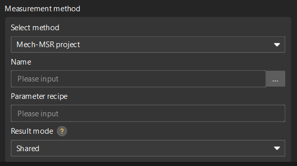
Result mode: Set the method to use the measurement result of the feature binding project.
-
Shared: When a feature-bound project finishes running, all features bound to the project will parse the measurement results.
-
Exclusive: When the project bound by a feature finishes running, only the feature that triggered the project to run will parse the measurement result.
-
-
-
Click OK.
Create a Cylinder Feature
Please follow these steps to create a cylinder feature:
-
On the Mech-Metrics Configuration interface, under the Feature tab, click Cylinder.
-
In the Create Cylinder Feature dialog box, set the following information:
-
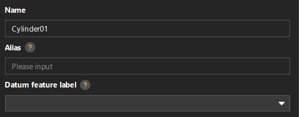
Set Name, Alias, and Datum feature label based on actual situation.
-
Alias: Used to associate the feature name in the CMM report.
-
Datum feature label: When this feature is used as the datum feature, it needs to be labeled. Datum feature labels are used in GD&T controls. For more information, see Configure GD&T Control Items.
-
-
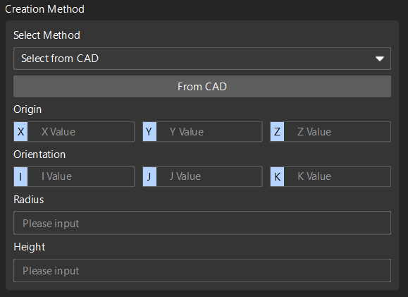
Set the creation method: The Select method is Select from CAD by default. The software will automatically input Origin (X, Y, Z), Orientation (I, J, K), Radius and Height.
-
Set the measurement method: The Select method is Mech-MSR project by default. Select the project corresponding to the feature in the drop-down list of the Name, and set the Parameter recipe and Result mode according to needs.
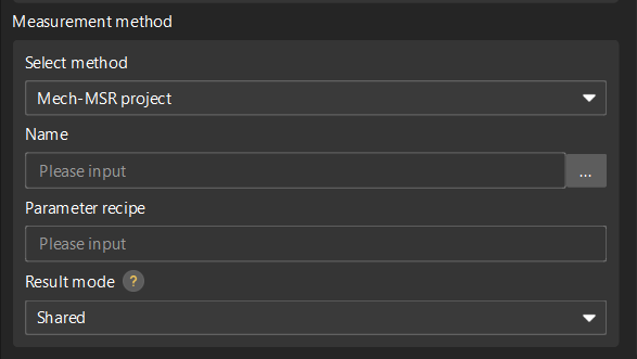
Result mode: Set the method to use the measurement result of the feature binding project.
-
Shared: When a feature-bound project finishes running, all features bound to the project will parse the measurement results.
-
Exclusive: When the project bound by a feature finishes running, only the feature that triggered the project to run will parse the measurement result.
-
-
-
Click OK.
Create a Point Feature
Follow the steps below to create a point feature:
-
In the Configuration interface of Mech-Metrics, under the Feature tab, click Point.
-
In the Create Point Feature dialog box, set the following information:
-
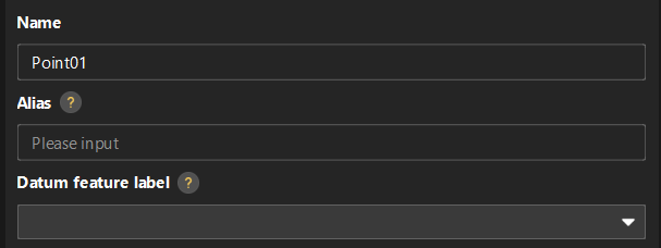
Set Name, Alias, and Datum feature label based on actual situation.
-
Alias: Used to associate the feature name in the CMM report.
-
Datum feature label: When this feature is used as the datum feature, it needs to be labeled. Datum feature labels are used in GD&T controls. For more information, see Configure GD&T Control Items.
-
-
Set the method for creating (either):
-
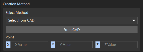
Select from CAD: The software will automatically enter the coordinates of the point (X, Y, Z).
-
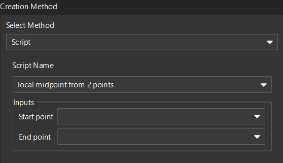
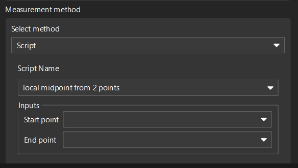
Script: Select a script name, and enter the start point and end point.
-
-
Set the measurement method (either):
-
Mech-MSR project: Select the project corresponding to the feature in the drop-down list of the Name, and set the Parameter recipe and Result mode according to actual needs.
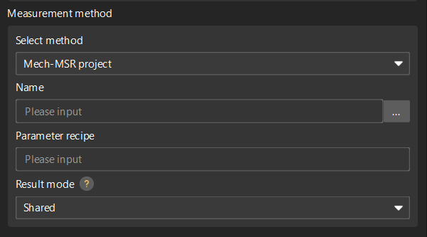
Result mode: Set the method to use the measurement result of the feature binding project.
-
Shared: When a feature-bound project finishes running, all features bound to the project will parse the measurement results.
-
Exclusive: When the project bound by a feature finishes running, only the feature that triggered the project to run will parse the measurement result.
-
-
Script: Select the corresponding measurement script.
-
-
-
Click OK.
Create a Line Feature
Follow the steps below to create a line feature:
-
In the Configuration interface of Mech-Metrics, under the Feature tab, click Line.
-
In the Create Line Feature dialog box, set the following information:
-
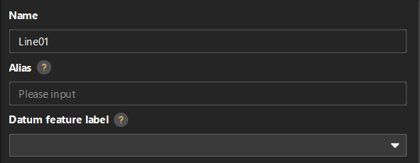
Set Name, Alias, and Datum feature label based on actual situation.
-
Alias: Used to associate the feature name in the CMM report.
-
Datum feature label: When this feature is used as the datum feature, it needs to be labeled. Datum feature labels are used in GD&T controls. For more information, see Configure GD&T Control Items.
-
-
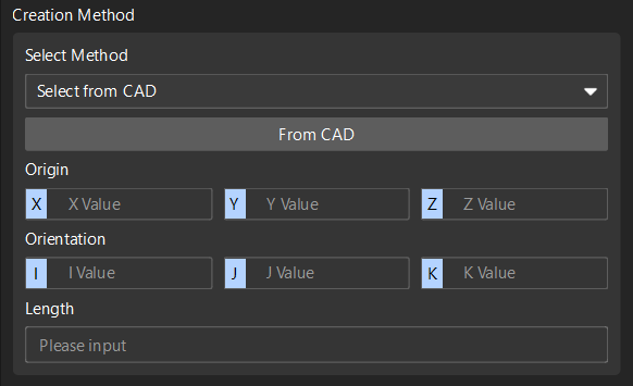
Set the method for creating (either):
-
Select from CAD: The software will automatically input Origin (X, Y, Z), Orientation (I, J, K) and Length.
-
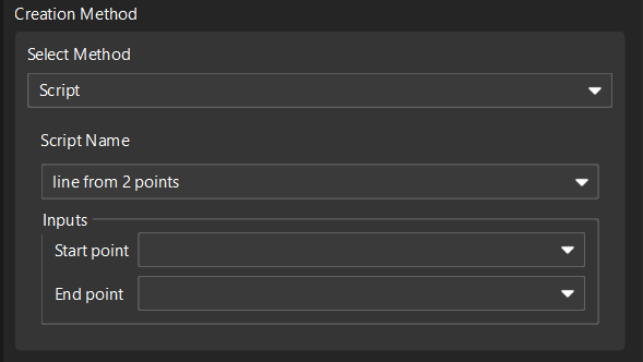
Script: Select the script Create line from two points, and input the start point and end point.
-
-
Set the measurement method (either):
-
Mech-MSR project: Select the project corresponding to the feature in the drop-down list of the Name, and set the Parameter recipe and Result mode according to actual needs.
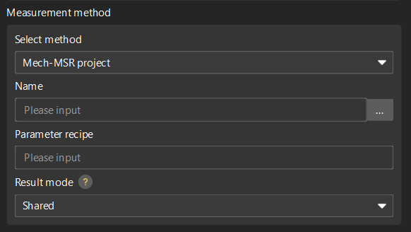
Result mode: Set the method to use the measurement result of the feature binding project.
-
Shared: When a feature-bound project finishes running, all features bound to the project will parse the measurement results.
-
Exclusive: When the project bound by a feature finishes running, only the feature that triggered the project to run will parse the measurement result.
-
-
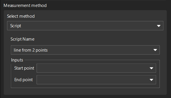
Script: Select the corresponding measurement script.
-
-
-
Click OK.
Create a Plane Feature
Follow these steps to create a plane feature:
-
In the Configuration interface of Mech-Metrics, under the Feature tab, click Plane.
-
In the Create Plane Feature dialog box, set the following information:
-
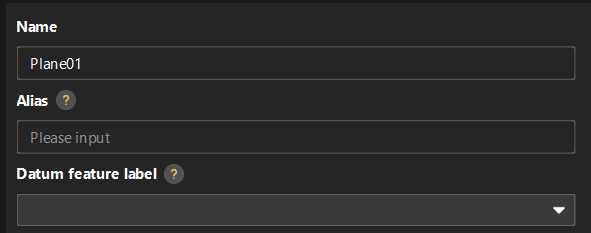
Set Name, Alias, and Datum feature label based on actual situation.
-
Alias: Used to associate the feature name in the CMM report.
-
Datum feature label: When this feature is used as the datum feature, it needs to be labeled. Datum feature labels are used in GD&T controls. For more information, see Configure GD&T Control Items.
-
-
Set the method for creating (either):
-
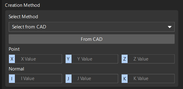
Select from CAD: The software will automatically input point (X, Y, Z) and normal (I, J, K).
-
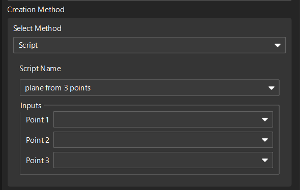
Script: Select the script Create plane from three points, and input the coordinates of the three points.
-
-
Set the measurement method (either):
-
Mech-MSR project: Select the project corresponding to the feature in the drop-down list of the Name, and set the Parameter recipe and Result mode according to actual needs.
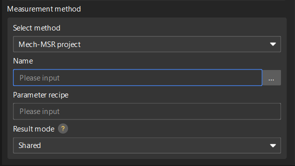
Result mode: Set the method to use the measurement result of the feature binding project.
-
Shared: When a feature-bound project finishes running, all features bound to the project will parse the measurement results.
-
Exclusive: When the project bound by a feature finishes running, only the feature that triggered the project to run will parse the measurement result.
-
-
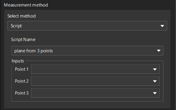
Script: Select the corresponding measurement script.
-
-
-
Click OK.
Create a Rectangle Feature
Follow these steps to create a rectangle feature:
-
In the Configuration interface of Mech-Metrics, under the Feature tab, click Rectangle.
-
In the Create Rectangle Feature dialog box, set the following information:
-
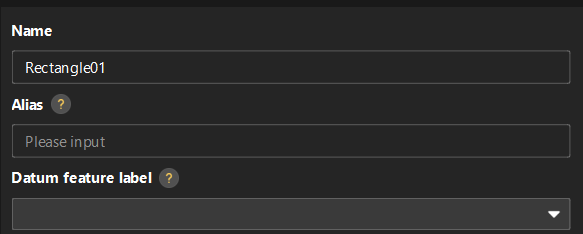
Set Name, Alias, and Datum feature label based on actual situation.
-
Alias: Used to associate the feature name in the CMM report.
-
Datum feature label: When this feature is used as the datum feature, it needs to be labeled. Datum feature labels are used in GD&T controls. For more information, see Configure GD&T Control Items.
-
-
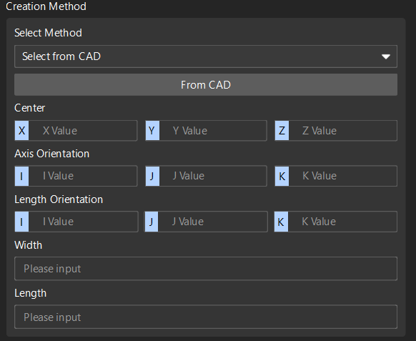
Set the creation method: Only Select from CAD is available. The software will automatically input the following parameters:
-
Center: X, Y, Z
-
Axis Orientation: I, J, K
-
Length Orientation: I, J, K
-
Width and Length
-
-
Set the measurement method: Only Mech-MSR project is available. Select the project corresponding to the feature in the drop-down list of the Name, and set the Parameter recipe and Result mode according to actual needs.
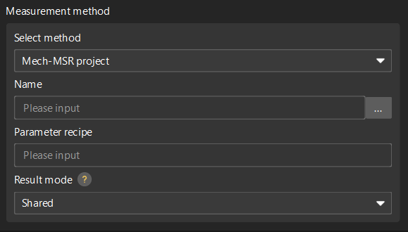
Result mode: Set the method to use the measurement result of the feature binding project.
-
Shared: When a feature-bound project finishes running, all features bound to the project will parse the measurement results.
-
Exclusive: When the project bound by a feature finishes running, only the feature that triggered the project to run will parse the measurement result.
-
-
-
Click OK.
Create a Pattern Feature
Follow these steps to create a pattern feature:
-
In the Configuration interface of Mech-Metrics, under the Feature tab, click Pattern.
-
In the Create Pattern Feature dialog box, set the following information:
-
Set Name and Alias.
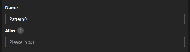
Alias: Used to associate the feature name in the CMM report.
-
In the Select features area, select the desired features.
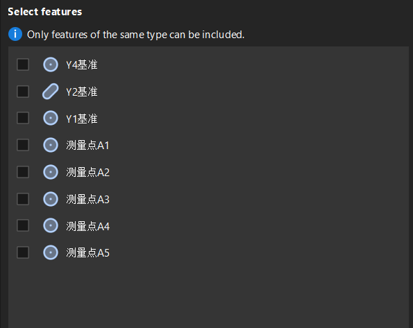
Only features of the same type can be selected for a pattern.
-
-
Click OK.
Create a Distance Feature
Follow the steps below to create a distance feature:
-
In the Configuration interface of Mech-Metrics, under the Feature tab, click Distance.
-
In the Create Distance Feature dialog box, set the following information:
-
Set Name and Alias.
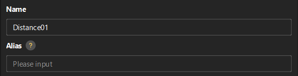
Alias: Used to associate the feature name in the CMM report.
-
Set the method for creating (either):
-
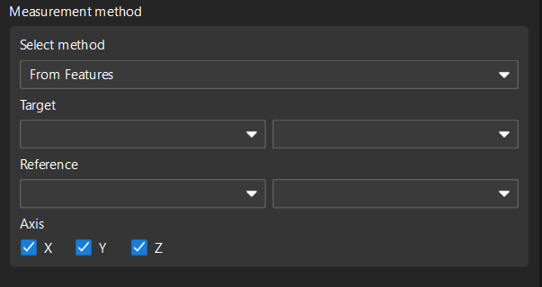
From Features: Select the Target and Reference, and select the Axis (X, Y, Z) according to needs.
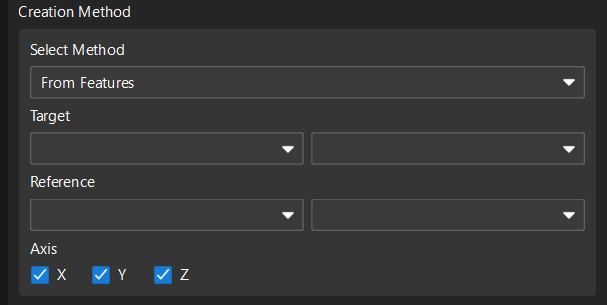
-
Manual input: Enter the distance directly.
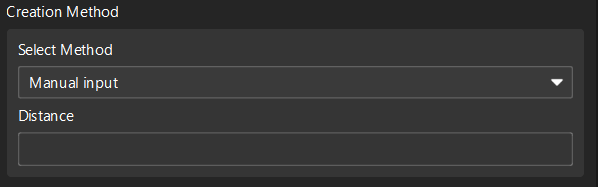
-
-
Set the measurement method (either):
-
From Features: Select the Target and Reference, and then select the Axis.
-
Mech-MSR project: Select the project corresponding to the feature in the drop-down list of the Name, and set the Parameter recipe and Result mode according to actual needs.
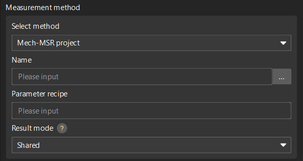
Result mode: Set the method to use the measurement result of the feature binding project.
-
Shared: When a feature-bound project finishes running, all features bound to the project will parse the measurement results.
-
Exclusive: When the project bound by a feature finishes running, only the feature that triggered the project to run will parse the measurement result.
-
-
-
-
Click OK.
Create an Angle Feature
Follow these steps to create an angle feature:
-
In the Configuration interface of Mech-Metrics, under the Feature tab, click Angle.
-
In the Create Angle Feature dialog box, set the following information:
-
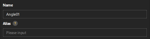
Set Name and Alias.
Alias: Used to associate the feature name in the CMM report.
-
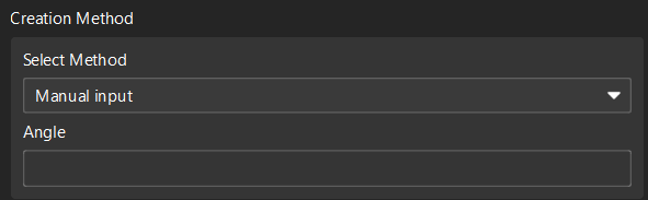
Set the method for creating (either):
-
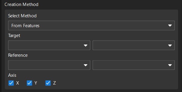
From Features: Select the Target and Reference, and select the Axis (X, Y, Z) according to needs.
-
Manual input: Input the angle directly.
-
-
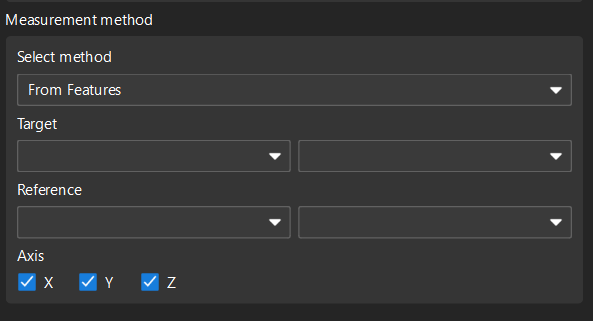
Set the measurement method (either):
-
From Features: Select the Target and Reference, and then select the Axis.
-
Mech-MSR project: Select the project corresponding to the feature in the drop-down list of the Name, and set the Parameter recipe and Result mode according to actual needs.
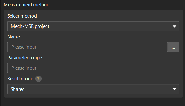
Result mode: Set the method to use the measurement result of the feature binding project.
-
Shared: When a feature-bound project finishes running, all features bound to the project will parse the measurement results.
-
Exclusive: When the project bound by a feature finishes running, only the feature that triggered the project to run will parse the measurement result.
-
-
-
-
Click OK.
Modify a Feature
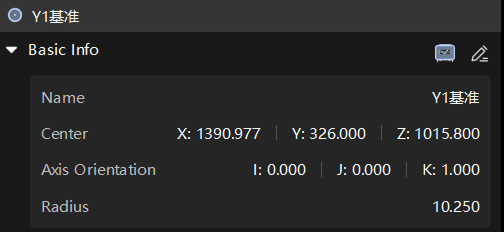
The first created circle feature is named Circle01 by default. To modify the configurations of the created Circle01 feature, perform the following operations:
-
Click Circle01 in the resource tree. In the Basic Info section on the right parameter panel, click the edit button
 .
.
-
In the feature creation dialog box, modify configurations of the feature (such as the name or nominal values of the feature) and click OK.
Delete a Feature
The first created circle feature is named Circle01 by default. For example, to delete the Circle01 feature, use one of the following methods:
-
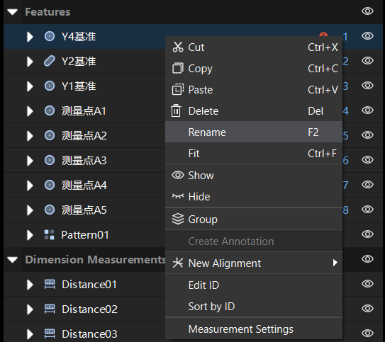
Right-click Circle01 in the resource tree and select Delete.
-
Click Circle01 in the resource tree, and then press the Delete key.