Deploy Drift Correction Feature in Solution (Manual)
This section describes how to manually deploy the drift correction feature in an ETH vision system. During deployment, manually move the robot to each calibration sphere image-capturing point and validate the points one by one. After deployment, the robot auto-correction program can correct accuracy drift periodically.
Deployment Process Overview
The manual deployment process is shown below.

-
Learn about the deployment prerequisites: Learn about the prerequisites for the deployment of “Auto-correct accuracy drift in ETH vision system” in the solution.
-
Complete the preparations: Prepare all the necessary materials.
-
Collect workstation data: Connect to the camera, select the project and parameter groups, and set the calibration sphere dimensions and deployment workflow.
-
Plan calibration sphere image-capturing points: Set the scene and target point cloud space dimensions, generate image-capturing points, and check their number and distribution.
-
Manually validate image-capturing points: Manually move the robot to each point, enter its flange pose, and validate the repeatability of the calibration sphere poses.
-
Export robot program: Select the robot brand and export the robot auto-correction program.
-
Enable auto-correction: Enable the auto-correction feature in the picking project. Then adjust and load the robot auto-correction program to correct the accuracy drift of the vision system during production.
-
Check deployment result: Check the deployment result of the “Auto-correct accuracy drift in ETH vision system” feature in the solution.
Deployment Prerequisites
The following prerequisites should be met before proceeding with the deployment:
-
Ensure that the vision solution for picking has been deployed for the workstation.
-
Ensure that the camera, robot, and extrinsic parameter accuracy checks have been completed, and that the robot is able to pick target objects successfully. Please refer to Error Analysis Tool for specific instructions.
-
Ensure there is enough space at the robot end to fasten the calibration sphere.
Preparations
If all the prerequisites can be met, you can start to prepare the materials and mount the calibration sphere.
-
Check the materials.
Open the ETH kit packaging box and ensure it contains a calibration sphere, a soft nozzle air blower, and other components.
-
Mount the calibration sphere.
Refer to the Mounting Precautions and mount the calibration sphere at the robot end.
-
Warm up the camera.
Use the Warm Up Tool to warm up the camera and prevent temperature increases during data acquisition from affecting intrinsic parameter accuracy.
Start Deployment
-
Open the Auto-correct accuracy drift in ETH vision system tool.
After completing the preparations, select on the menu bar to open the deployment tool.
-
Select manual deployment.
In the Deployment wizard area on the tool’s home page, select the robot type and model. Select Manual under Deployment method and robot control mode, then click Start deployment to enter the manual deployment process.
|
Here, we use a 60 mm-diameter calibration sphere as an example to illustrate the deployment process of the “Auto-Correct Accuracy Drift in ETH Vision System” solution. |
Collect Workstation Data
This step sets the camera, project, calibration sphere dimensions, and deployment workflow to provide information for planning calibration sphere image-capturing points.
Connect to a Camera
-
Connect to the camera.
Click Connect to camera to select and connect to the camera used in the picking project.
-
Select the project and parameter groups.
Select the picking project that requires drift correction and the corresponding Calibration parameter group and Configuration parameter group to specify the project and camera configuration for this deployment.
Set Calibration Sphere Dimensions
-
Set the calibration sphere diameter.
Set Calibration sphere diameter according to the sphere actually used on-site.
Select Deployment Workflow
-
Select the workflow type.
Set Workflow type according to the on-site conditions to determine the number of image-capturing points to plan for each layer.
-
Simplified workflow: Plans 3 image-capturing points per layer. This workflow is suitable for a single target object located near the center of the camera’s field of view. If the distance from the calibration sphere at its lowest limit position to the lowest-layer target object exceeds 200 mm, select Standard workflow.
-
Standard workflow: Plans 9 image-capturing points per layer. This workflow is suitable for multiple target objects, objects distributed across the camera’s field of view, or objects away from the center of the field of view.
-
After completing the settings, click Next to plan calibration sphere image-capturing points.
Plan Calibration Sphere Image-Capturing Points
This step generates the number and distribution of image-capturing points based on the scene and target point cloud space dimensions.
Select Scenario
-
Set the target object layout.
Under Scene, select Random stacked or Multilayer arrangement according to the on-site conditions. If you select Multilayer arrangement, also set the number of layers.
-
Set the distance from the calibration sphere at its lowest limit position to the lowest-layer target object.
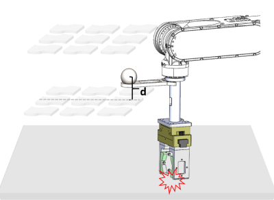
When Random stacked is selected, set Distance from lowest sphere to lowest object. This is the distance between the calibration sphere center and the lowest-layer target object when the robot moves the sphere to its achievable lowest position, as shown below.
-
Set the target point cloud space dimensions.
Set the length, width, and height of Space dimensions of target point cloud according to the extent of the target point cloud actually used for localization.
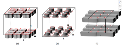
(a) If the matching is performed using the point cloud of the object’s upper surface, the height of the target point cloud is the distance from the upper surface of the highest-layer object to the upper surface of the lowest-layer object.
(b) If the matching is performed using the local point cloud of the object’s upper surface, the height of the target point cloud is the distance from the upper surface of the highest-layer object to the upper surface of the lowest-layer object.
(c) If the matching is performed using multiple layers of surface point clouds, the height of the target point cloud is the distance from the upper surface of the highest-layer object to the lower surface of the lowest-layer object.
-
For single-layer objects, when the point cloud of the object’s upper surface is used for matching, the height of the target point cloud is 0.
-
If partitions exist between the layers of the target object, the height of the target point cloud should include the height of the partition.
-
-
Generate calibration sphere image-capturing points.
After completing the scene settings, click Generate image-capturing points. The tool generates the number and distribution of image-capturing points based on the settings.
Check Planning Results
-
Check the image-capturing point planning parameters.
On the image-capturing point planning results tab, check the distance from the lowest sphere to the lowest object, the distance between two layers, the same-layer lengthwise spacing between spheres, the same-layer widthwise spacing between spheres, and the total number of layers.
-
Check the spatial distribution of image-capturing points.
Switch to the Scene visualization results tab and check that the point distribution matches the actual workstation.
-
Proceed to manual validation.
After confirming the planning results, click Next to manually validate the image-capturing points.
Manually Validate Image-Capturing Points
This step calculates the repeatability of the calibration sphere poses at each point to ensure accurate and reliable drift correction data. The interface displays the number of the point being validated and the validation progress.
Validate Image-capturing Points
After obtaining the distribution of the calibration sphere, the repeatability of calibration sphere poses from each image-capturing point should be calculated to ensure accurate and reliable data for accuracy drift correction.
|
It is recommended to validate the image-capturing points layer by layer from bottom to top, completing one layer before proceeding to the next. |
-
Clear the validation area.
Remove trays or bins to prevent collisions when the robot moves to the planned points.
-
Move the robot.
Move the robot to any image-capturing point on the first layer and enter the current flange pose in the Pose tool area to record the actual point.
Please ensure that no collisions occur during the robot’s movement to this pose. It is recommended to jog the robot to the target pose at a low speed and observe whether there will be any collisions.
If there is a possibility of collision in the robot path, the position of the calibration sphere can be adjusted in any direction, provided the movement of the image-capturing point remains within 100 mm.
-
Set ROI for the calibration sphere.
Click Adjust ROI to set a 3D ROI for the calibration sphere in the pop-up window, then click Ok.
-
The ROI must fully enclose the calibration sphere, leaving a margin equal to the sphere’s diameter on all sides.
-
You only need to set the 3D ROI for the calibration sphere when validating the first image-capturing point.
-
-
Validate the image-capturing points.
Click the Capture image to validate button, and three continuous image acquisitions will be triggered to calculate the repeatability of the calibration sphere poses. If the validation succeeds, a recognition result window will pop up with a message indicating “Validation success.”
-
Validate the next image-capturing point.
Move the robot to the next point, click Next, enter the current flange pose, and click Capture image to validate to validate this point.
To view the previous image-capturing point, click Previous.
-
Complete validation of the current layer.
Repeat the robot movement, flange pose recording, and image capture for validation until all points on the current layer have been validated.
-
Validate the remaining layers.
If there are multiple layers, repeat the operations layer by layer from bottom to top until all points have been validated.
After validating all image-capturing points, click Next to export the robot program.
Export Robot Program
Check the List of Image-Capturing Points
-
Check the image-capturing point list.
Check the robot flange pose for each point and confirm that it matches the point recorded during manual validation. The exported robot program uses these points.
Generate Robot Program
-
Export the robot auto-correction program.
Select the robot brand from the drop-down list in the Generate robot program area, then click Export. The exported program collects calibration sphere poses and generates drift correction data during production.
|
If the auto-correction program has not been exported or has been lost, you can also select the robot brand and export the program on the Check Deployment Result page. |
After exporting the program, click Next to enable auto-correction. During deployment, the tool automatically generates the following drift correction projects in the current solution:
-
Drift_Collection_ETH: This project collects the calibration sphere poses at each image-capturing point.
-
Drift_Calculation: The project generates the drift correction data based on the calibration sphere poses collected by the “Drift_Collection_ETH” project.
|
Do not modify the two drift correction projects or any related parameters. At the same time, during subsequent drift correction processes, ensure that the names and numbers of the drift correction projects remain unchanged. When the drift correction projects are generated, a point cloud model of the calibration sphere will be automatically generated in the target object editor as well. Please do not modify the name or other configuration of this point cloud model. |
Enable Auto-Correction
After validating the image-capturing points, enable auto-correction in the picking project, then adjust, load, and test the robot auto-correction program so that it can periodically correct accuracy drift during production.
Enable Auto-Correction in Picking Project
Select Auto-Correct Accuracy Drift in Vision System in the Output or Path Planning Step of the picking project to enable auto-correction.
Adjust the Robot Program
Before loading, check and adjust the exported robot auto-correction program according to the on-site conditions. Teach the Home position and set the IPC IP address and port number in the communication parameters to establish communication with the robot. Also check that the reference frame, tool, and image-capturing points match the actual workstation. The following FANUC example shows the communication parameters and Home position to modify. The Home position is P[50].
J P[50] 50% FINE ;
CALL MM_INIT_SKT('8','127.0.0.1',50000,5) ;|
If using a FANUC robot, the example robot program must first be compiled into a TP file before being loaded into the robot. This step is not required for other robots. |
If using a robot brand other than FANUC, you can refer to the workflow description of the robot auto-correction program below, along with the auto-correction example program for FANUC robots and key statement explanations, to adjust or create an auto-correction program for your specific robot brand.
Click here to view the basic workflow of the robot auto-correction program.
Step 1: Determine the robot reference frame and tool reference frame.
Step 2: Move the robot to the Home position.
Step 3: Move the robot to the calculated image-capturing point 1 on the lowest layer.
Step 4: Once the robot reaches the image-capturing point 1, switch the parameter recipe in the project for collecting calibration sphere poses (Drift_Collection_ETH) to the one corresponding to the image-capturing point.
Step 5: Once the parameter recipe is switched, trigger the “Drift_Collection_ETH” project to run and collect the calibration sphere poses at image-capturing point 1.
Step 6: Follow steps 3 to 5 for the other image-capturing points on the current layer to collect the calibration sphere poses at each point.
Step 7: From bottom to top, repeat steps 3–6 for the remaining image-capturing points on other layers to collect the calibration sphere poses at each point.
Step 8: After completing the pose collection for image-capturing points on all layers, switch the parameter recipe of the Drift_Calculation project for generating drift correction data.
Step 9: Trigger the “Drift_Calculation” project to run and generate the drift correction data.
Step 10: Move the robot to the Home position.
Click here to see an example of a FANUC robot auto-correction program.
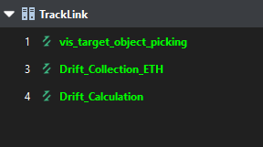
The following auto-correction program, developed based on the workflow outlined above, uses a FANUC robot. In this example program, the number of image-capturing points for the calibration sphere is 9, the index of the project for collecting the calibration sphere poses is 3, and the index of the project for generating drift correction data is 4.
| The robot auto-correction program utilizes several registers. During program execution, ensure these registers are not occupied. |
  UFRAME_NUM=0 ;
  UTOOL_NUM=1 ;
J P[50] 50% FINE ;
  CALL MM_INIT_SKT('8','127.0.0.1',50000,5) ;
  R[50:StartIndex]=1 ;
  R[52:EndIndex]=9 ;
  R[53:CameraIndex]=1 ;
  R[54:CollectionId]=3 ;
  R[55:CalculationId]=4 ;
  PR[51]=P[51] ;
  PR[52]=P[52] ;
  PR[53]=P[53] ;
  PR[54]=P[54] ;
  PR[55]=P[55] ;
  PR[56]=P[56] ;
  PR[57]=P[57] ;
  PR[58]=P[58] ;
  PR[59]=P[59] ;
  FOR R[51:mm_i]=R[50:StartIndex] TO R[52:EndIndex] ;
  R[56]=R[51:mm_i]-R[50:StartIndex]+51 ;
L PR[R[56]] 1000mm/sec FINE ;
  WAIT   3.00(sec) ;
  CALL MM_SET_MOD(R[54:CollectionId],R[51:mm_i]) ;
  WAIT   1.00(sec) ;
  CALL MM_START_VIS(R[54:CollectionId],0,1,100) ;
  WAIT   3.00(sec) ;
  ENDFOR ;
  CALL MM_SET_MOD(R[55:CalculationId],R[53:CameraIndex]) ;
  WAIT   1.00(sec) ;
  CALL MM_START_VIS(R[55:CalculationId],0,1,100) ;
  WAIT   3.00(sec) ;
J P[50] 50% CNT100 ;
END ;
Click here to view detailed workflow descriptions for the FANUC robot auto-correction program.
| This table only explains the key statements; for detailed explanations of each statement in the FANUC robot auto-correction program, refer to the example program for FANUC robots. |
| Workflow | Code and description | ||
|---|---|---|---|
Set the reference frame |
Define the world reference frame as the robot reference frame and the flange reference frame as the tool reference frame. |
||
Move the robot to the Home position |
Move the robot to the Home position where the robot is away from target objects and the surrounding equipment.
|
||
Initialize communication parameters |
Set the robot port number to 8, with the IP address of the IPC set to 127.0.0.1. The port number used for communication between the IPC and the robot is 50000, and the timeout period is 5 minutes. |
||
Store the start and end values of the parameter recipe ID corresponding to the image-capturing points |
When exporting the robot program, the tool calculates the start and end values of parameter recipe IDs corresponding to the image-capturing points, storing these values in numerical registers. |
||
Define parameter recipe IDs for the camera and indexes of drift correction projects |
Assign the parameter recipe ID corresponding to the camera as 1, the project index for the “Drift_Collection_ETH” project as 3, and the project index for the “Drift_Calculation” project as 4. These values are stored in numerical registers. |
||
Store image-capturing points |
Store the nine image-capturing points (P[51] to P[59]) into position registers (PR[51] to PR[59]) for subsequent robot movements to the respective positions. |
||
Calculate position register numbers for the parameter recipe IDs corresponding to the image-capturing points through looping |
Using a loop, iterate through the parameter recipe IDs of all image-capturing points (1 to 9) for calibration spheres. Calculate the value of R[56] using this formula, representing the position register number corresponding to the current image-capturing point’s parameter recipe ID. In this example: R[50:StartIndex] = 1, when the parameter recipe ID R[51:mm_i] = 2, R[56] = 2 - 1 + 51 = 52. As the program progresses, the robot moves to the image-capturing point stored in position register PR[52]. |
||
Move the robot to the image-capturing point |
The robot moves to each image-capturing point in linear motion, with a velocity of 1000 mm/sec. |
||
Switch the parameter recipe of the project for collecting the calibration sphere poses |
Switch the parameter recipe of the “Drift_Collection_ETH” project (whose project index is 3) for collecting calibration sphere poses to parameter recipe R[51:mm_i](1~9). |
||
Trigger the project for collecting calibration sphere poses |
Trigger the “Drift_Collection_ETH” project (whose project index is 3) to run and collect calibration sphere poses at each image-capturing point. Once all calibration sphere poses are collected, the loop ends, and the collected calibration sphere poses will be used to generate drift correction data. |
||
Switch the parameter recipe of the project for generating the drift correction data |
After collecting calibration sphere poses at all image-capturing points, switch the parameter recipe of the “Drift_Calculation” project (whose project index is 4) for generating drift correction data to parameter recipe 1.
|
||
Trigger the project for generating the drift correction data to run |
Trigger the “Drift_Calculation” project (whose project index is 4) to run and generate drift correction data based on the collected calibration sphere poses. |
||
Move the robot to the Home position |
Move the robot to the Home position where the robot is away from target objects and the surrounding equipment. |
Load Robot Program
After adjusting the program and checking the points, load the program to the robot for subsequent testing and production auto-correction. For a FANUC robot, compile the program into a TP file first.
|
For instructions on loading the auto-correction program, refer to “Standard Interface Communication Configuration” for the corresponding robot brand in Standard Interface Communication. |
Test Robot Program
After loading the program, test it at low speed first and check each motion path to ensure that the robot does not collide with target objects or surrounding equipment. The robot moves to the corresponding image-capturing points and triggers the drift correction projects to capture images of the calibration sphere, collect its poses, and correct accuracy drift using the generated drift correction data.
|
According to the robot brand used in your project, you can select and test the robot auto-correction program by referring to the “Set up Standard Interface Communication” guide for the corresponding robot brand in Standard Interface Communication. |
After running the robot auto-correction program, correction records will be generated and can be viewed on the Data monitoring dashboard.
Test Picking the Target Objects
Run the robot picking program and check the picking results. If the robot can pick target objects accurately, the deployment is successful.
Note that after the test picking is complete, to ensure long-term stability in actual production, you must configure the alert threshold on the Data monitoring dashboard. The threshold is typically recommended to be set at 10 mm. If the drift compensation exceeds this threshold, verify that the camera and robot tool are securely mounted and check whether the robot’s zero position has been lost.
Determine the Correction Cycle
Set the auto-correction interval in the robot program according to the on-site conditions to collect calibration sphere poses periodically and correct accuracy drift periodically.
Now you have completed the deployment of “Auto-correct accuracy drift in ETH vision system” in the solution. Click the Finish button to return to the tool’s home page.
|
After deployment, it is recommended to export the current configuration parameter group of the camera to a local backup. This ensures that if the camera is damaged and needs to be replaced, the configuration parameter group can still be retrieved. |
Check Deployment Result
-
Check the camera deployment information.
After deployment, click Check deployment at the bottom of the tool’s home page and select the camera to view the corresponding image-capturing point and recipe information.
-
Export the robot program again as needed.
If the previously exported auto-correction program is lost or needs to be exported again, select the corresponding brand from the robot brand drop-down list and click Export.