Convert 2D Point to 3D Pose
Function Description
This Step converts the 2D pose or 2D shape of a target object detected by a 2D camera into a 3D pose in the specified base frame. It also outputs data such as pose offsets according to the selected application scenario.
Figure description: P1 is the taught reference pose for picking, P2 is the taught flange pose during capture, and P3 is the object pose in the base frame.
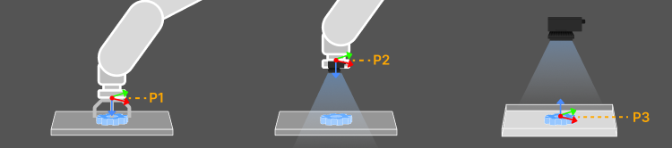
Usage Scenario
This Step is suitable for scenarios where a 2D camera is used to locate planar target objects and the localization results are used for positioning and picking or placement correction. It is typically used after localization Steps such as 2D Matching or 2D Blob Analysis, and before the Output Step.
Input and Output
Input
| Input Port | Data Type | Description |
|---|---|---|
2D Pose |
Pose2D[] |
The 2D pose of the target object. |
2D Shape |
Shape2D[] |
The 2D shape data of the target object, including contours, regions, or other geometric features. The system automatically extracts reference points from the shape for pose conversion. |
Real-Time Placement Pose |
Pose[] |
The pose provided by an upstream localization Step. It is used to calculate the flange pose for placement correction of the current target object. This input is used only in the Placement Correction (Non-Fixed Placement Position) scenario. |
Output
| Output Port | Data Type | Description |
|---|---|---|
3D Pose |
Pose[] |
The converted 3D pose. In the Object Pose Output scenario, this is the target object pose. In the Positioning and Picking or Placement Correction scenarios, this is the corresponding robot flange pose. |
Pose Offset |
Pose[] |
The offset of the current 3D pose from the reference pose, calculated in the selected base frame. This port outputs offsets only in the X, Y, and Rz directions. X and Y represent translational offsets, and Rz represents the angular offset around the Z-axis. |
Relative Pose Transformation |
Pose[] |
The X, Y, and Rz transformation quantities required to transform the reference pose into the current 3D pose. The transformation is calculated in the selected base frame and represents planar positional and angular changes. Relative Pose Transformation × Taught Reference Pose = 3D Pose. |
Parameter Description
Object Pose Output
This scenario converts the 2D pose into the 3D pose of the target object in the selected base frame. It does not calculate a robot tool pose from a taught picking or placement pose. Subsequent Steps can use the object pose for picking, placement, or other pose processing.
|
When the output object pose is expressed in the TCP frame, its Z-axis points in the positive direction of the TCP frame’s Z-axis. |
| Parameter | Description |
|---|---|
Application Scenario |
Select the application scenario based on the actual requirements. The corresponding input ports and parameters are displayed after a scenario is selected. Value List: Object Pose Output, Positioning and Picking, Placement Correction (Fixed Placement Position), Placement Correction (Non-Fixed Placement Position) |
Base Frame |
Sets the base frame used to output the 3D pose or pose offset. The robot frame is used by default. To use a custom base frame, enter its pose in the robot frame. |
Input Data Type |
Specifies the type of input data. Value List: 2D Pose, 2D Shape |
Image Acquisition Step |
Selects the 2D camera Step that provides the camera intrinsics, extrinsics, and calibration results. Select the camera Step corresponding to the current 2D localization result. |
Enable Height Compensation |
Enable this parameter when the target object plane and the camera calibration reference plane are parallel but at different heights. The Step compensates for scale and pose offset based on Target Object Real-Time Height and Target Object Reference Height. This parameter is only applicable when the camera optical axis is perpendicular to the work plane. It is not recommended when the camera optical axis is tilted. |
Target Object Reference Height |
The distance from the camera to the calibration reference plane, measured in millimeters (mm) along the camera optical axis. Set this parameter when height compensation is enabled. |
Target Object Real-Time Height |
The distance from the camera to the target object plane, measured in millimeters (mm) along the camera optical axis. Set this parameter when height compensation is enabled. |
Positioning and Picking
This scenario calculates the robot flange pose for picking the current target object based on the reference target object’s 2D pose and reference picking pose. It is suitable for picking non-stacked target objects from a pallet or flat target objects from a conveyor belt.
| Parameter | Description |
|---|---|
Application Scenario |
Select the application scenario based on the actual requirements. The corresponding input ports and parameters are displayed after a scenario is selected. Select Positioning and Picking for this scenario. Value List: Object Pose Output, Positioning and Picking, Placement Correction (Fixed Placement Position), Placement Correction (Non-Fixed Placement Position) |
Base Frame |
Sets the base frame used to output the 3D pose or pose offset. The robot frame is used by default. To use a custom base frame, enter its pose in the robot frame. |
Input Data Type |
Specifies the type of input data. Value List: 2D Pose, 2D Shape |
Image Acquisition Step |
Selects the 2D camera Step that provides the camera intrinsics, extrinsics, and calibration results. Select the camera Step corresponding to the current 2D localization result. |
Reference Target Object 2D Pose |
The 2D pose of the reference target object detected at the capture point. This pose is typically obtained from the data stream output by the previous Step to this input port. |
Reference Picking Pose |
The robot flange pose when picking the reference target object. This is the flange pose in the base frame read from the teach pendant. |
Enable Height Compensation |
Enable this parameter when the target object plane and the camera calibration reference plane are parallel but at different heights. The Step compensates for scale and pose offset based on Target Object Real-Time Height and Target Object Reference Height. This parameter is only applicable when the camera optical axis is perpendicular to the work plane. It is not recommended when the camera optical axis is tilted. |
Target Object Reference Height |
The distance from the camera to the calibration reference plane, measured in millimeters (mm) along the camera optical axis. Set this parameter when height compensation is enabled. |
Target Object Real-Time Height |
The distance from the camera to the target object plane, measured in millimeters (mm) along the camera optical axis. Set this parameter when height compensation is enabled. |
Placement Correction (Fixed Placement Position)
This scenario calculates a placement correction based on the localization deviation of the target object and places it at a fixed position. It is suitable when the position and orientation of the placement location remain unchanged during operation. Placement correction is only supported with the Eye-to-Hand (ETH) camera mounting mode.
| Parameter | Description |
|---|---|
Application Scenario |
Select the application scenario based on the actual requirements. The corresponding input ports and parameters are displayed after a scenario is selected. Select Placement Correction (Fixed Placement Position) for this scenario. Value List: Object Pose Output, Positioning and Picking, Placement Correction (Fixed Placement Position), Placement Correction (Non-Fixed Placement Position) |
Base Frame |
Sets the base frame used to output the 3D pose or pose offset. The robot frame is used by default. To use a custom base frame, enter its pose in the robot frame. |
Input Data Type |
Specifies the type of input data. Value List: 2D Pose, 2D Shape |
Image Acquisition Step |
Selects the 2D camera Step that provides the camera intrinsics, extrinsics, and calibration results. Select the camera Step corresponding to the current 2D localization result. |
Reference Target Object 2D Pose |
The 2D pose of the reference target object detected at the capture point. This pose is typically obtained from the data stream output by the previous Step to this input port. |
Reference Capture Pose |
The robot flange pose at the capture point during teaching. This is the flange pose in the base frame read from the teach pendant. |
Reference Placement Pose |
The robot flange pose when placing the reference target object at the target position during teaching. This is the flange pose in the base frame read from the teach pendant. |
Obtain Flange Pose from Parameters |
When selected, the robot flange pose entered in Flange Pose during Capture takes priority. Even if the Communication Component successfully obtains a flange pose, the pose entered here is used. |
Flange Pose during Capture |
The robot flange pose at the capture point. This is the flange pose in the base coordinate frame read from the teach pendant. |
Robot Name Used in Communication Configuration |
Enter the robot model name. It must match the model of the robot connected through the Communication Component. |
Enable Height Compensation |
Enable this parameter when the target object plane and the camera calibration reference plane are parallel but at different heights. The Step compensates for scale and pose offset based on Target Object Real-Time Height and Target Object Reference Height. This parameter is only applicable when the camera optical axis is perpendicular to the work plane. It is not recommended when the camera optical axis is tilted. |
Target Object Reference Height |
The distance from the camera to the calibration reference plane, measured in millimeters (mm) along the camera optical axis. Set this parameter when height compensation is enabled. |
Target Object Real-Time Height |
The distance from the camera to the target object plane, measured in millimeters (mm) along the camera optical axis. Set this parameter when height compensation is enabled. |
Placement Correction (Non-Fixed Placement Position)
After the target object has been picked, this scenario further compensates for the picking deviation based on the current localization result and calculates the final placement correction together with the Real-Time Placement Pose. It is suitable when the actual position or orientation of the placement location varies between runs. Placement correction is only supported with the Eye-to-Hand (ETH) camera mounting mode.
| Parameter | Description |
|---|---|
Application Scenario |
Parameter description: Select the application scenario according to your requirements. The corresponding input ports and parameters will be displayed. Select Placement Correction (Non-Fixed Placement Position) for this scenario. Value List: Object Pose Output, Positioning and Picking, Placement Correction (Fixed Placement Position), Placement Correction (Non-Fixed Placement Position) |
Base Frame |
Parameter description: Sets the base frame used to output the 3D pose or pose offset. The robot frame is used by default. To use a custom base frame, enter its pose in the robot frame. |
Input Data Type |
Parameter description: Specifies the type of input data. Value List: 2D Pose, 2D Shape |
Image Acquisition Step |
Parameter description: Selects the 2D camera Step that provides the camera intrinsics, extrinsics, and calibration results. Select the camera Step corresponding to the current 2D localization result. |
Reference Target Object 2D Pose |
Parameter description: The 2D pose of the reference target object detected during image capture. This pose is usually obtained from the data stream output by the previous Step and connected to this input port. |
Reference Capture Pose |
Parameter description: The robot flange pose at the capture point during teaching. This is the flange pose in the base frame, as read from the teach pendant. |
Reference Placement Pose |
Parameter description: The robot flange pose when the robot places the reference target object at the target position during teaching. This is the flange pose in the base frame, as read from the teach pendant. |
Obtain Flange Pose from Parameters |
Parameter description: When selected, the robot flange pose entered in the Flange Pose during Capture parameter takes priority. This pose is used even if the Communication Component successfully obtains a flange pose. |
Flange Pose during Capture |
Parameter description: The robot flange pose at the capture point. This is the flange pose in the base frame, as read from the teach pendant. |
Robot Service Name Used in Communication Configuration |
Parameter description: Enter the robot model name. It must match the robot model connected through the Communication Component. |
Enable Height Compensation |
Parameter description: Enable this function when the target object plane and the camera calibration reference plane are parallel but at different heights. The Step compensates for scale and pose offsets based on the Target Object Real-Time Height and Target Object Reference Height. This function is only applicable when the camera optical axis is perpendicular to the work plane; it is not recommended when the camera optical axis is tilted. |
Target Object Reference Height |
Parameter description: The distance from the camera to the calibration reference plane, measured in millimeters (mm) along the camera optical axis. Set this parameter when height compensation is enabled. |
Target Object Real-Time Height |
Parameter description: The distance from the camera to the target object plane, measured in millimeters (mm) along the camera optical axis. Set this parameter when height compensation is enabled. |