Quick Camera Replacement
In actual production, collisions between the camera and other objects can easily alter its extrinsic parameters. When this occurs, the camera typically needs to be replaced, followed by re-calibration. Alternatively, if replacing the camera is not an option, you can manually set the pick points by jogging the robot. However, both approaches increase workload and downtime.
To resolve this issue, the Quick camera replacement feature is integrated into the “Auto-correct accuracy drift in ETH vision system” tool. The operation workflow is shown below.

-
Migrate configuration parameter group: Mount the new camera and quickly import the configuration parameter group of the old camera into the new one to save time on parameter adjustment.
-
Update camera configuration: After replacing the camera and updating the configuration parameter group, update the configurations related to the camera in the project.
-
Validate image-capturing points: Re-validate the image-capturing points to ensure accurate and reliable drift correction data can be obtained.
-
Check program running result: Check whether valid drift correction data is generated after the robot program runs.
-
Test picking: Guide the robot to pick the target object to verify the success of the quick camera replacement.
|
Migrate Configuration Parameter Group
Before replacing the camera, adjust the parameter group of the new camera to ensure that the calibration sphere’s point cloud quality is comparable to that acquired with the old camera. There are two methods to adjust the parameter group of the new camera, and this article will introduce the first method.
-
Import the parameter group from the old camera to the new camera.
-
Directly adjust the parameter group of the new camera.
The second method is suitable when the camera is damaged and cannot be connected. In such cases, mount the new camera directly and proceed with parameter adjustment.
Before replacing the camera, please migrate the configuration parameter group as required, ensuring the configuration parameter group of the old camera is quickly imported to the new camera, thereby reducing the subsequent camera adjustment time.
-
Export the configuration parameter group from the old camera.
Connect to the old camera in Mech-Eye Viewer and export the configuration parameter group to restore the configuration on the new camera.
-
Remove the old camera.
Disconnect the old camera’s power supply before removing it.
-
Mount and connect to the new camera.
Mount the new camera, connect the cables, and turn on the power. After confirming that all indicator lights show normal status, connect to the new camera in Mech-Eye Viewer.
When mounting the new camera, make sure that the mounting height and position of the new camera is the same as that of the old camera.
-
Import the configuration parameter group.
In Mech-Eye Viewer, import the configuration parameter group exported from the old camera into the new camera to reduce the need for parameter adjustment.
After completing the above steps, click Next to proceed with updating the camera configuration.
Update Camera Configuration
After migrating the configuration parameter group, please update the configurations related to the camera in the project.
-
Connect to the new camera.
Click Select camera to select and connect to the replacement camera.
-
Select the serial number of the old camera.
Select the serial number of the camera being replaced from the drop-down list to specify the camera configuration to update.
-
Update the camera configuration.
Click Update configuration to update the camera-related configuration in the project.
Validate Image-capturing Points
After replacing the camera, the image-capturing points where the calibration sphere images are captured should be re-validated to obtain accurate and reliable drift correction data.
|
Since the new camera is in a cold-start state, its intrinsic parameter accuracy may change due to temperature increases during image acquisition. Therefore, the camera should be warmed up in advance. Please refer to Warm Up Tool for detailed instructions. |
-
Move the robot to the image-capturing point.
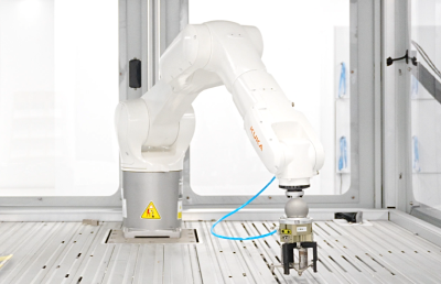
Move the robot at low speed to the flange pose corresponding to the image-capturing point to prepare for revalidating the repeatability of the calibration sphere poses.
Please ensure that no collisions occur during the robot’s movement to this pose. It is recommended to jog the robot to the target pose at a low speed and observe whether there will be any collisions.
-
Adjust the calibration sphere ROI.
Click Adjust ROI to adjust the sphere’s ROI and ensure that the sphere remains within the recognition region after camera replacement.
-
Validate the image-capturing point.
Click Capture image to validate to calculate the repeatability of the sphere poses at this point and confirm that reliable drift correction data can be obtained.
Repeat the above steps until all image-capturing points are validated, and click Save.
Check Program Running Result
After validating the image-capturing points, you should check the program running result, ensuring valid drift correction data is generated after the robot program runs.
-
Run the robot program.
Run the robot auto-correction program to collect calibration sphere poses and generate drift correction data for subsequent correction of accuracy drift.
-
Check the program running result.
After running the robot program, click the Start check button to check the running result of the robot program.
-
If the check passes, it indicates that valid drift correction data has been generated after running the auto-correction program. Then you can click the Finish button to proceed with the quick camera replacement.
-
If the check fails, it indicates that the robot auto-correction program did not generate valid drift correction data. In this case, it is recommended to rerun the robot auto-correction program to capture the calibration sphere poses.
-
Test Picking
-
Test picking and check the results.
Run the robot picking program and check the results. If the robot can pick target objects accurately, quick camera replacement is successful.