Feature Region (3D)
Feature regions define the target regions of processing during 3D Step runs.
Set a Feature Region
In some Steps, you can adjust the feature regions directly, while in others, you need to select the Use Feature Region parameter first under “Parameters” and then adjust the feature regions.
You can set the feature region in the following ways:
-
Adjust Feature Regions in 3D Data Viewer of Visualized Regions
-
Adjust the position of feature region(s) intuitively and roughly
-
Adjust the size of feature region(s) intuitively and roughly
-
-
Set Feature Region Parameters in the Parameter Configuration Panel
-
Set the feature region type
-
Adjust the position of feature region(s) precisely
-
Adjust the size of feature region(s) precisely
-
Add or delete feature region(s)
-
Adjust the Feature Region in the 3D Data Viewer of the Visualization Region
This method is used to roughly adjust the feature region(s).
|
|
|
|
Set Feature Region Parameters in the Parameter Configuration Panel
This method is used to fine-tune a feature region. In some Steps, you can set a feature region only when the Use Feature Region option is selected.
-
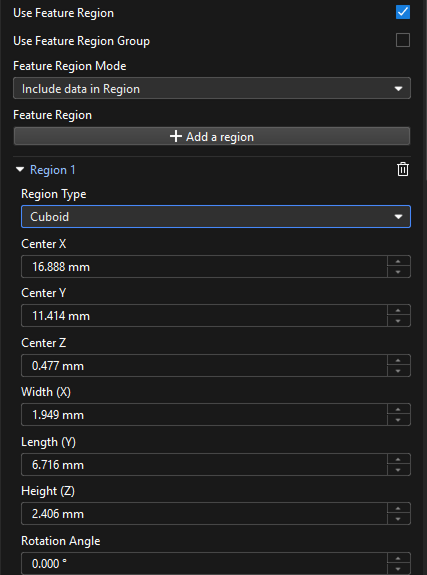
Feature Region
-
Add a feature region: Click the + Add a region button to add a new feature region.
If this button is greyed out in a Step, it means that the Step does not support the creation of a new feature region or the number of created feature regions has reached the upper limit. -
Expand Region1 (Example): Click ▶ to expand Region1.
-
Region Type: You can determine the type of a feature region. The options are cuboid, cylinder, elliptic cylinder and annular cylinder.
-
Center X/Y/Z: The center position of the feature region.
-
Width (X) / Length (Z) / Height (Z): The dimensions of the feature region.
-
Rotation Angle: The angle at which the feature region rotates counterclockwise around the Z-axis of the spatial reference frame in its initial position.
-
Inner Radius: the inner radius of the annular cylinder. This parameter is visible only when the region type is set as “Annular cylinder”.
-
-
Delete a feature region: Click
 to the right of Region2 (example) to delete this feature region. If the delete icon is grayed out, the feature region cannot be deleted.
 -
Transformation Matrix: Represents the translation and rotation transformations of the feature region, in the format of [x, y, z, qw, qx, qy, qz]. This parameter is for data display only and cannot be modified.
In this matrix, the first three values represent the translation of the feature region along the X, Y, and Z axes, respectively. For example, [0.1, −0.2, 0.5] (Unit: mm) indicates a translation of 0.1 mm along the positive X-axis, -0.2 mm along the negative Y-axis, and 0.5 mm along the positive Z-axis. The last four values represent the rotation of the feature region in quaternion form. For example, [1, 0, 0, 0] indicates no rotation.
Only when the Alignment Parameter Group input port of a Step has data and a feature region or feature regions are used in the Step, the Transformation Matrix parameter will be displayed after the Step is run.
-
Set the Feature Region(s)
When multiple target objects are regularly arranged, use the feature region combination to set feature regions in a grid.
The procedure of configuring this tool is shown below:
-
In the Parameters section, select Use Feature Region and then Use Feature Region Combination parameters.
-
In the Feature Regions Combination parameter panel, click the Open the editor button.
-
In the pop-up Feature Region Combination Editor window, perform the following steps:get an image, select feature regions, adjust parameters, and generate a feature region grid step. Then click Save.
In the drop-down menu under Open the editor in the Parameters section, select the desired feature region combination to the current Step.
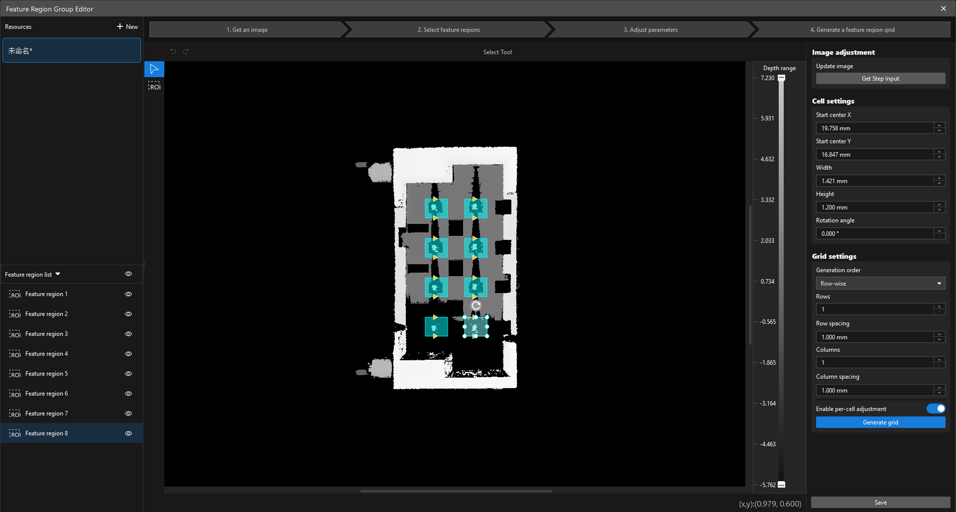
Capture Images
When the Feature Region Combination Editor window is opened, the system automatically loads the image from the current step. To refresh the image, click Get Step input in the Image Adjustment area on the right side of the window.
Feature Region Selection
-
Click the ROI Tool icon
 to select a feature region in the image.
 -
Adjust the drawn feature region in one of the following two ways:
-
Select the feature region to be adjusted. When Adjustment anchors appear on each side, drag the mouse to reposition the feature region. Select an adjustment anchor and drag the mouse to resize the feature region.
-
Select the feature region to be adjusted and set the cell settings on the right side of the window.
-
-
Click the blank area to draw the feature region.
Adjust Parameters
| Parameter | Description | ||
|---|---|---|---|
Image Adjustment |
Adjust the currently acquired images. Refresh the image: Click Get Step input to retrieve the image of the current step. |
||
Cell Settings |
Adjust the X coordinate, Y coordinate, width, height, and rotation angle of the selected cell. |
||
Grid |
Configure the method to generate the grid of feature regions, including the generation order (row or column), the number of rows, the number of columns, the row spacing, and the column spacing.
|
||
Allow individual cell adjustments |
|
Generate Feature Region Grid
-
Click Generate grid to generate an grid of feature regions based on the drawn cells and set parameters.
-
In the upper-left corner of resource area, you can rename the feature region combination and create a new resource according to your needs.
-
In the lower-left corner of Feature Region List area, you can view the generated feature regions. Supports exporting models, importing data, and exporting data.
|