Modbus TCP
Mech-MSR can communicate with external devices through Modbus TCP. Before you read the following content, make sure that the communication configuration has been completed in Mech-MSR.
About Modbus TCP
Mech-MSR supports communication with PLCs through the Modbus TCP protocol. In this communication mode, Mech-MSR acts as the server (slave) and the PLC acts as the client (master). All requests are initiated by the PLC, and Mech-MSR responds to them.
After the Modbus TCP communication service is enabled in Mech-MSR, the software starts listening on port 502 (default) for one or more Modbus clients.
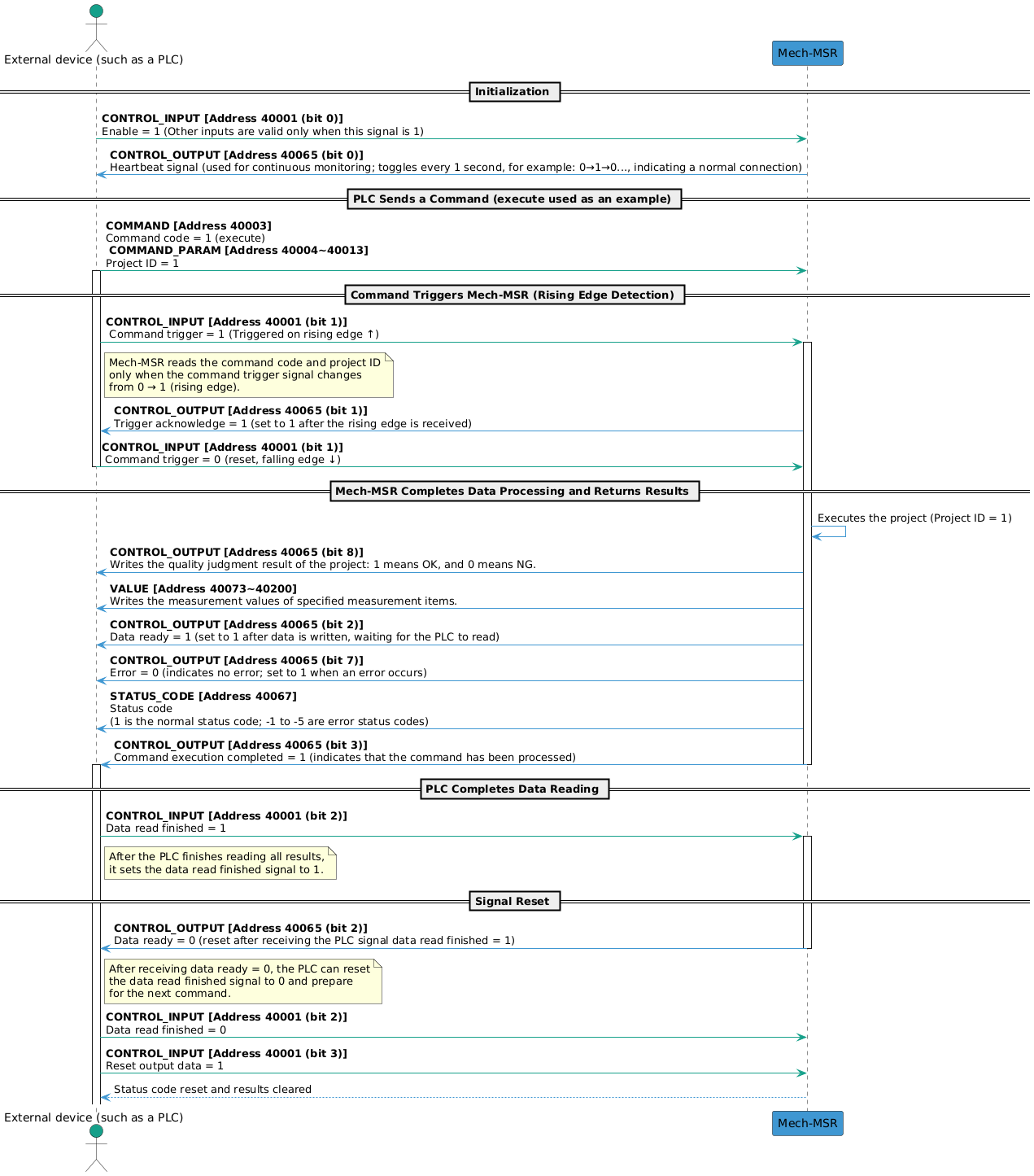
Communication Workflow
The workflow of Modbus TCP communication is shown in the figure below.
| See Input and Output Signals to learn the meaning of each signal. |
Input and Output Signals
|
Mech-MSR supports the following standard Modbus function codes for accessing holding registers.
|
|
Holding register addresses are logical addresses (displayed addresses), such as During actual communication, the base address is 1, which means holding register addresses start from |
| Input (from the PLC to Mech-MSR) | Output (from Mech-MSR to the PLC) | ||||||
|---|---|---|---|---|---|---|---|
Module |
Name |
Bytes Occupied |
Holding Register Address (4x) |
Module |
Name |
Bytes Occupied |
Holding Register Address (4x) |
Enable |
1 byte |
40001 |
Heartbeat |
1 byte |
40065 |
||
Command trigger |
Trigger acknowledge |
||||||
Data read finished |
Data ready |
||||||
Reset output data |
Command execution completed |
||||||
Reserved |
Reserved |
||||||
Reserved |
Reserved |
||||||
Reserved |
Reserved |
||||||
Reserved |
Error |
||||||
Reserved |
3 bytes |
First 1 byte: 40001; last 2 bytes: 40002 |
Overall judgment result |
1 byte |
40065 |
||
Reserved |
|||||||
Reserved |
|||||||
Reserved |
|||||||
Reserved |
|||||||
Reserved |
|||||||
Reserved |
|||||||
Reserved |
|||||||
Reserved |
2 bytes |
40066 |
|||||
Command code |
2 bytes |
40003 |
Status code |
2 bytes |
40067 |
||
Command parameter 1 |
2 bytes |
40004 |
RESERVED |
Reserved |
2 bytes |
40068 |
|
Command parameter 2 |
2 bytes |
40005 |
Judgment result of ID 1 Judgment result of ID 2 Judgment result of ID 3 ... |
8 bytes |
40069~40072 |
||
Command parameter 3 |
2 bytes |
40006 |
|||||
Command parameter 4 |
2 bytes |
40007 |
|||||
Command parameter 5 |
2 bytes |
40008 |
|||||
Command parameter 6 |
2 bytes |
40009 |
Measurement result of ID 1 Measurement result of ID 2 Measurement result of ID 3 ... |
256 bytes (4 bytes x 64) |
40073~40200 |
||
Command parameter 7 |
2 bytes |
40010 |
|||||
Command parameter 8 |
2 bytes |
40011 |
|||||
Command parameter 9 |
2 bytes |
40012 |
|||||
Command parameter 10 |
2 bytes |
40013 |
|||||
Variable 1 |
4 bytes |
40014~40015 |
|||||
Variable 2 |
4 bytes |
40016~40017 |
|||||
Variable 3 |
4 bytes |
40018~40019 |
|||||
Variable 4 |
4 bytes |
40020~40021 |
|||||
Variable 5 |
4 bytes |
40022~40023 |
|||||
Variable 6 |
4 bytes |
40024~40025 |
|||||
Variable 7 |
4 bytes |
40026~40027 |
|||||
Variable 8 |
4 bytes |
40028~40029 |
|||||
Variable 9 |
4 bytes |
40030~40031 |
|||||
Variable 10 |
4 bytes |
40032~40033 |
|||||
RESERVED |
Reserved |
62 bytes |
40034~40064 |
||||
Input (from the PLC to Mech-MSR)
CONTROL_INPUT
| Address | Data | Description |
|---|---|---|
0.0 |
Enable (Boolean) |
Only when the enable signal is set to 1 are the other input signals considered valid. |
0.1 |
Command trigger (Boolean) |
Mech-MSR reads the command code and command parameters only when the command trigger signal changes from 0 to 1 (rising edge). After Mech-MSR returns the Trigger Acknowledge signal, the command trigger signal can be set to 0. |
0.2 |
Data read finished (Boolean) |
After the PLC finishes reading the data, set this signal to 1. Only after the PLC receives the Data Ready signal changing to 0 can this signal be set to 0. |
0.3 |
Reset output data (Boolean) |
When this signal is set to 1, the judgment results and measurement results received by the PLC (output) are cleared. At this point, the PLC can send a new command, and the related status code signals are also reset. |
0.4 |
Reserved (Boolean) |
Reserved field. |
0.5 |
Reserved (Boolean) |
Reserved field. |
0.6 |
Reserved (Boolean) |
Reserved field. |
0.7 |
Reserved (Boolean) |
Reserved field. |
1.0~3.7 |
Reserved (Byte) |
Reserved field. |
COMMAND & COMMAND_PARAM
The following table lists the supported commands in the current protocol and their corresponding command codes (COMMAND), command parameters (COMMAND_PARAM), and descriptions.
| Command | COMMAND | COMMAND_PARAM | Description |
|---|---|---|---|
execute |
1 |
Project ID. Only 1 project ID can be set at a time. |
Used to trigger a project to run and obtain the project’s judgment results and measurement results. |
trigger |
2 |
Project ID. 1 to 4 project IDs can be set at a time. |
Used to trigger a project to run. |
return |
3 |
Project ID. Only 1 project ID can be set at a time. |
Used to obtain the judgment results and measurement results of the specified project. |
judge |
4 |
Used to obtain the overall quality judgment result of the specified project or the quality judgment results of individual measurement items. |
|
value |
5 |
Mainly used to obtain the measurement values of the specified project. |
|
recipe |
6 |
Project ID and parameter recipe ID. |
Used to switch the parameter recipe used by a project. |
solution |
7 |
Solution ID. |
Used to switch a solution. |
SetNumVar |
8 |
Global variable ID. Only 1 can be set at a time. |
Used to set the value of a numeric global variable. The variable value is passed through VAR_INPUT. |
GetNumVar |
9 |
Global variable ID. Only 1 can be set at a time. |
Used to read the value of a numeric global variable. The result is returned through VALUE. |
|
VAR_INPUT
When the SetNumVar command is executed, the set value is written to VAR_INPUT.
| Holding Register Address (4x) | Data | Description |
|---|---|---|
40014~40015 |
Variable 1 (Float) |
Numeric input parameter 1. |
40016~40017 |
Variable 2 (Float) |
Numeric input parameter 2. |
40018~40019 |
Variable 3 (Float) |
Numeric input parameter 3. |
40020~40021 |
Variable 4 (Float) |
Numeric input parameter 4. |
40022~40023 |
Variable 5 (Float) |
Numeric input parameter 5. |
40024~40025 |
Variable 6 (Float) |
Numeric input parameter 6. |
40026~40027 |
Variable 7 (Float) |
Numeric input parameter 7. |
40028~40029 |
Variable 8 (Float) |
Numeric input parameter 8. |
40030~40031 |
Variable 9 (Float) |
Numeric input parameter 9. |
40032~40033 |
Variable 10 (Float) |
Numeric input parameter 10. |
Output (from Mech-MSR to the PLC)
CONTROL_OUTPUT
| Address | Data | Description |
|---|---|---|
0.0 |
Heartbeat signal (Boolean) |
System heartbeat. It toggles every second. It can be used to determine whether the communication connection between the PLC and Mech-MSR is normal or disconnected. |
0.1 |
Trigger acknowledge (Boolean) |
When Mech-MSR receives the rising edge of the Command Trigger signal, this signal is set to 1. When the command trigger signal falls, this signal is set to 0. |
0.2 |
Data ready (Boolean) |
Mech-MSR writes data to the output port and waits for the PLC to read it. When the Data Read Finished signal is 1, this signal is set to 0. |
0.3 |
Command execution completed (Boolean) |
When command execution ends, this signal is set to 1, indicating that the command has been processed. |
0.4 |
Reserved (Boolean) |
Reserved field. |
0.5 |
Reserved (Boolean) |
Reserved field. |
0.6 |
Reserved (Boolean) |
Reserved field. |
0.7 |
Error (Boolean) |
When the status code returned by Mech-MSR is not 1, this signal is set to 1 to indicate an error. |
1.0 |
Overall judgment result (Boolean) |
The overall judgment result of the project. 1 indicates pass (OK), and 0 indicates fail (NG). |
1.1~1.7 |
Reserved (Boolean) |
Reserved field. |
2.0~3.7 |
Reserved (Byte) |
Reserved field. |
| Quality judgment rules must be configured for the project in the Output Management window of Mech-MSR, and the measurement items considered during quality judgment must be determined. Only after the configuration is complete can valid quality judgment results be obtained. |
STATUS_CODE
Mech-MSR may return the following status codes:
-
Normal status code: 1, indicating that the command was executed successfully.
-
Error status codes: -1, -2, -3, -4, and -5. See Error Codes for details.
JUDGE
The quality judgment results of measurement items added on the Communication Output tab in the Output Management window are returned here. 1 indicates pass (OK), and 0 indicates fail (NG).
| Up to 64 judgment results can be output at one time for a single project. |
VALUE
The VALUE module can return the following data:
-
The measurement results of the measurement items added on the Communication Output tab in the Output Management window.
-
The values of numeric global variables read when the
GetNumVarcommand is executed.
| Up to 64 measurement values can be output at one time for a single project. |